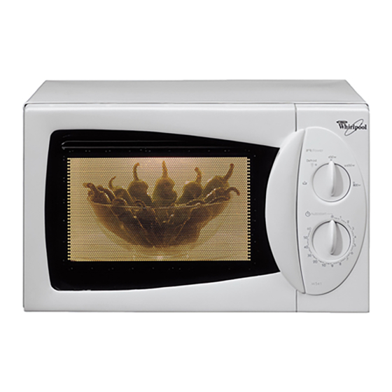
Summary of Contents for Whirlpool AVM541
- Page 1 WHIRLPOOL ELECTRICAL APPLIANCES CO. LTD. SERVICE MANUAL WHIRLPOOL ELECTRICAL APPLIANCES COMPANY LIMITED SERVICE INFO MANUAL MODEL: AVM541 SKU No.: 853854158291 DATE: October 6, 2005 REVISION: a Ref: 54158291a PAGE 1 OF 17...
-
Page 2: Table Of Contents
WHIRLPOOL ELECTRICAL APPLIANCES CO. LTD. SERVICE MANUAL CONTENTS SPECIFICATIONS SAFETY PRECAUTIONS INSTALLATION REQUIREMENTS GENERAL GROUNDING INSTRUCTIONS SCHEMATIC DIAGRAM MICROWAVE AND MICROWAVE LEAKAGE TEST MICROWAVE TEST MICROWAVE LEAKAGE TEST TROUBLE SHOOTING GUIDE CAUTION AND IMPORTANCE MICROWAVE LEAKAGE QUICK REFERENCE MAJOR COMPONENT TESTS... -
Page 3: Specifications
WHIRLPOOL ELECTRICAL APPLIANCES CO. LTD. SERVICE MANUAL SPECIFICATION Model AVM541 Outer dimension(H x W x D) 285x456x392mm Volume of cavity 17.8Liter Basic function Microwave only cooking Control Mechanical timer control 60-minute timer 5-level microwave power level Power supply 220V, 60 Hz, single phase... -
Page 4: Safety Precautions
WHIRLPOOL ELECTRICAL APPLIANCES CO. LTD. SERVICE MANUAL SAFETY PRECAUTIONS This manual is intended for use by personnel with adequate background in electrical, electronic and mechanical engineering. Any improper attempt to repair this oven may result in personal injury and property damage. The manufacturer or seller cannot be hold responsible for the interpretation of this manual nor can they assume any liability in connection with its use. -
Page 5: Installation Requirements
WHIRLPOOL ELECTRICAL APPLIANCES CO. LTD. SERVICE MANUAL INSTALLATION REQUIREMENTS GENERAL 1. The oven should be placed on a flat and stable surface 2. Place the oven away from high temperature and steam sources. 3. Clearance of at least 5cm (2”) on each side must be provided to allow adequate ventilation. -
Page 6: Schematic Diagram
WHIRLPOOL ELECTRICAL APPLIANCES CO. LTD. SERVICE MANUAL SCHEMATIC DIAGRAM Ref: 54158291a PAGE 6 OF 17... -
Page 7: Microwave And Microwave Leakage Test
WHIRLPOOL ELECTRICAL APPLIANCES CO. LTD. SERVICE MANUAL MICROWAVE AND MICROWAVE LEAKAGE TESTS MICROWAVE TEST The following is a simple test to check if the appliance is generating microwave energy. This test is not intended to be an accurate test. An accurate measurement of output power must be performed under strict control following the IEC standard. -
Page 8: Trouble Shooting Guide
WHIRLPOOL ELECTRICAL APPLIANCES CO. LTD. SERVICE MANUAL 5. Pull the door to the position at which the oven is just about to turn off due to the interlock switch action, scan the door perimeter for microwave leakage. 6. Maximum allowable leakage is 4 mW/cm 7. - Page 9 WHIRLPOOL ELECTRICAL APPLIANCES CO. LTD. SERVICE MANUAL 3. If leakage is found worst around the door perimeter, adjust the interlock support or change the door. QUICK SERVICE REFERENCES PROBLEM POINTS TO CHECK Cavity lamp does not light, but other 1. Lamp burnt.
-
Page 10: Major Component Tests
WHIRLPOOL ELECTRICAL APPLIANCES CO. LTD. SERVICE MANUAL MAJOR COMPONENT TESTS HV TRANSFORMER 1. Remove lead wire. 2. Measure the resistance of the winding using an ohm meter 3. Primary winding 3 ohm (approx.) 4. Secondary winding 100 ohm (approx.) 5. Filament winding 0 ohm (approx.) HV CAPACITOR 1. - Page 11 WHIRLPOOL ELECTRICAL APPLIANCES CO. LTD. SERVICE MANUAL Oven door Primary switch Secondary Monitor status switch switch Open Open Open Close Close Close Close Open 1. The interlock and monitor switches positions are not service adjustable. To repair the door, remount the door and fasten the screws on the door hinges.
- Page 12 WHIRLPOOL ELECTRICAL APPLIANCES CO. LTD. SERVICE MANUAL PART LIST The following pages contain the part list for this model. Ref: 54158291a PAGE 12 OF 17...
- Page 13 WHIRLPOOL ELECTRICAL APPLIANCES CO. LTD. SERVICE MANUAL Item no. Description Service parts no. Outer wrapping 4619-640-29951 Power cord assembly 4619-640-31362 Back spacer 4619-641-38501 Front back support 4619-644-12485 Oven foot 4619-641-39202 Oven foot expand nail 4619-641-41901 Lamp holder 4619-648-77101 Lamp(20W) 4619-648-77091...
- Page 14 WHIRLPOOL ELECTRICAL APPLIANCES CO. LTD. SERVICE MANUAL Item no. Description Service parts no. Magnetron 4619-648-33341 Thermostat(145°C) 4619-648-56402 Capacitor support 4619-644-12222 HV capacitor 4619-646-51103 HV diode 4619-646-97721 Fan air guide 4619-641-89323 Fan motor 4619-647-81511 Fan wheel(five) 4619-641-89262 Interlock assy 4619-640-39241 Fuse holder...
- Page 15 WHIRLPOOL ELECTRICAL APPLIANCES CO. LTD. SERVICE MANUAL Item no. Description Service parts no. Door body assembly 4619-640-47831 Inner foil Inner frame 4619-641-89341 Extension spring 4619-644-11221 Glass support 4619-641-89401 Door hook 4619-641-91032 Front door glass 4619-656-95371 Door frame 4619-641-88852 Ref: 54158291a...
- Page 16 WHIRLPOOL ELECTRICAL APPLIANCES CO. LTD. SERVICE MANUAL Item no. Description Service parts no. Timer 4619-648-33161 Control panel 4619-641-89611 Knob Spring Bushing 4619-640-45881 Spring Coil Other information: Item no. Description Language Service parts no. English 4619-652-60744 Ref: 54158291a PAGE 16 OF 17...
- Page 17 WHIRLPOOL ELECTRICAL APPLIANCES CO. LTD. SERVICE MANUAL Revision Log Revision Description Revised by Revision Date Original Revision Wang Wei Guo Sep 20,2001 Revising PN in the service part list Liang min yi October 6, 2005 Ref: 54158291a PAGE 17 OF 17...


