
Related Manuals for JRC JLR-21


Summary of Contents for JRC JLR-21
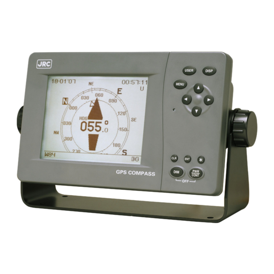
- Page 1 JLR - 21/31 21/31 GPS COMPASS GPS COMPASS INSTRUCTION INSTRUCTION MANUAL MANUAL...
- Page 3 Foreword Thank you for purchasing the JRC GPS Compass JLR-21/31. This unit uses signals from GPS satellites to determine the ship’s heading. Thoroughly read this instruction manual before operating the equipment. Keep this manual nearby the equipment to allow ready access to it if necessary. It may provide valuable information on how to deal with a given situation that may arise during the operation.
-
Page 4: Before Commencing The Operation
Before Commencing the Operation Symbols Several symbols are used in this manual to ensure safety and proper operation of the equipment and to avoid possible human injury or property damage. These symbols and their meanings are shown below. Please read and understand these symbols before proceeding to read this manual. -
Page 5: Precautions Upon The Operation
Do not perform internal inspections or modifications of the equipment. Inspection or modification by unauthorized personnel may result in fire, electric shock, or equipment failure. Please consult with JRC or an affiliate to perform internal inspections or repair. When disposing of the used lithium battery, place insulating tape over the battery terminals, or otherwise insulate the battery. - Page 6 Do not place items on top of the equipment. Doing so may result in equipment failure, malfunction, or injury. Please consult with JRC or an affiliate to perform installation. Installation by unauthorized personnel may result in malfunction. Only use the specified batteries. Failure to do so may result in battery leakage or rupture, resulting in fire, injury, or equipment failure.
- Page 7 It is not possible to measure also the tsunami. When you install JLR-21/31 in retractable mast, please observe the following strictly. ① An unusual vibration or an unusual shock should not occur.
- Page 8 CAUTION Do not bend the cables included with this equipment excessively, or twist them or subject them to other strong forces. Doing so may result in damage to the interior or exterior of the cables, and may result in fire or electrocution. Do not install the equipment in places subject to vibration or shock.
-
Page 9: Appearance Of The Equipment
Appearance of the Equipment ● Standard Equipment NWZ-4701 Display Unit NNN-21 Sensor Unit NNN-31 Sensor Unit... -
Page 10: Table Of Contents
Contents Foreword ....................i Before Commencing the Operation ............. ii Precautions Upon the Operation ............iii Appearance of the Equipment ............vii Section 1 EQUIPMENT OVERVIEW ..........1-1 Functions ....................1-1 Features ....................1-1 Configuration ..................1-2 Construction ..................1-4 System Diagram ................... - Page 11 5.2.6 Changing the Display ..............5-8 5.2.7 Displaying Satellite Information ............5-9 5.2.8 Alert History Display ..............5-10 5.2.9 Anchor Watch Settings ..............5-11 Main Menu ..................5-13 5.3.1 Display Settings ................5-14 5.3.1.1 Adjusting the Contrast ............5-15 5.3.1.2 Brightness Settings (DIMMER) ..........
- Page 12 Section 8 Disposal ................ 8-1 Disposal of the Equipment ..............8-1 Disposal of Used Batteries ..............8-1 Section 9 Specifications ............... 9-1 Display Unit (NWZ-4701) ..............9-1 9.1.1 Panel ....................9-1 9.1.2 Power Supply .................. 9-1 9.1.3 Environment ..................9-1 9.1.4 Dimensions and Mass ..............
-
Page 13: Section 1 Equipment Overview
DGPS beacon station. Since this equipment outputs the bearing information at high speed, if the unit is interfaced to a JRC radar unit, it is possible to fully draw the capabilities of the radar and ARPA. 1.2 Features ●... -
Page 14: Configuration
1.3 Configuration Standard Configuration JLR-21 Name Model/Code Q’ty Notes Display Unit NWZ-4701 Power Cable CFQ-7257 2m / With fuse holder Fuse MF60NR 250V 2 2Amps. Clamp Filter TFC-23-11-14 5MBAT00002 MPNN47010 Model Identification Plate Model Identification Plate MPNN47078 For Panel Installation Screws... - Page 15 Option Name Model/Code Q’ty Notes 3m / 12 cores / Serial data Data Cable CFQ-5374 transmission Data Cable CFQ-5404 3m / 14 cores / Dry contact signal Data Extension Cable CFQ-7249 20m / 14 cores / For sensor extension Beacon Connecting Cable CFQ-7250 For beacon receiver connection 14 connector / for sensor extension...
-
Page 16: Construction
1.4 Construction NWZ-4701 Display Unit Dimensions: 267.4 x 162 x 85 mm Mass: Approximately 2.3 kg... - Page 17 NNN-21/31 Sensor Unit NNN-21 Dimensions: 691 x 285mm Mass: Approximately 5.9 kg NNN-31 Dimensions: 1152 x 286 mm Mass: Approximately 10 kg...
-
Page 18: System Diagram
1.5 System Diagram JLR-21 JLR-31 NNN-21 NNN-31 Sensor Unit Sensor Unit JLR-4341 or JLR-4331 DGPS Receiver CFQ-7248 Data Cable (10m) Power DC12V CFQ-7250 (for beacon receiver) Data Cable SENSOR CFQ-5374 DATA Radar Data Cable (3m) IN/OUT 1 ECDIS/GPS Plotter IEC61162/NSK x 2... -
Page 19: Section 2 Installation
Section 2 Installation CAUTION Please consult with JRC or an affiliate to perform installation. Installation by unauthorized personnel may result in malfunction. -
Page 20: Sensor Installation
Sensor Installation CAUTION Do not bend the cables included with this equipment excessively, or twist them or subject them to other strong forces. Doing so may result in damage to the interior or exterior of the cables, and may result in fire or electrocution. Do not install the equipment in places subject to vibration or shock. - Page 21 CAUTION When you install JLR-21/31 in retractable mast, please observe the following strictly. ① An unusual vibration or an unusual shock should not occur. ② When the mast has retracted, please stop use. Because normal operation cannot be performed. ③ A difference should not occur in the position by retracting.
- Page 22 If this occurs, replace both the bolt and the nut with a new bolt and nut. If bolt loosening occurs frequently, please consult with a JRC technician. Install the sensor as horizontally to the ship as possible. If it is tilted largely, direction...
- Page 23 ● Cable Connection Procedure The unit shown in the figure is the NNN-21, which is almost identical to the NNN-31. Installing the clamp filter or connecting the extension cable requires a self-bonding tape and vinyl tape. Apply RTV rubber or silicone rubber to waterproof the sensor unit. 1.
- Page 24 3. Connect the included cable to the sensor unit. Tighten the nut firmly in order to waterproof the connector (a click sounds when plugged in firmly). After connecting, apply RTV (Room Temperature Vulcanizing) rubber on the connector for additional waterproofing. Waterproofing 3.
- Page 25 ● Installation Procedure The unit shown in the figure is the NNN-21, which is almost identical to the NNN-31. Provide a mounting plate as shown below, and secure the sensor unit. Use M10 hex bolts, washers, spring washers, and nuts to secure it. Tighten the bolt by 3430 N-cm of torque (350 kg-cm).
- Page 26 3. Fix the clamp filter (large) to the installation pole by using a bundling band (long). Fasten both ends of the large clamp filter. Fix it as closer to the antenna as possible. If it is impossible to fix to the pole, make holes in the mounting plate for bundling bands to go through, and fix the clamp filter to the mounting plate.
- Page 27 ● Installation Procedure for Optional Mount Base for NNN-21 1. Install the mounting base to the pole by using fixing brackets, M8 bolts, flat washers, spring washers, and nuts. Then, secure the sensor to the mounting base. Beware of the bow direction.
- Page 28 2. Fix both ends of the clamp filter (large) by using bundling bands (long) to secure the cable. Let the bands go through the holes of the mounting base. GPS1 GPS2 GPS3 Contact the pole end to Fix by bundling the mounting base.
- Page 29 Option installation trestle (MPBX44117) bundle list for NNN-21 Installation manual Installation trestle X 1 Fixed bracket X 3 M8 Bolts X 6 M10 Bolts X 3 M8 Bolt About 3. 1kg Stainless-Steel (UNIT: mm) 2-11...
- Page 30 ● About NNN-31 2-12...
- Page 31 2-13...
- Page 32 ● About Bird Repellent Rod (MPXP34012A) MPXP34012A 2-14...
-
Page 33: Didplay Unit Installation
Display Unit Installation WARNING Install this unit at least 1 m away from any magnetic compasses. Installation near a magnetic compass may result in interference with the magnetic compass, and may result in an accident. CAUTION Use the indicated screws when installing the display unit to a stable wooden surface. - Page 34 ● How to Flush Mount the Display < For fixing the Display from the rear side with four flush mount screws of the option > Refer to the diagram shown below for the mount hole and space. Installation later, reserve the open space to make maintain possible this equipment.
- Page 35 <The Display is fixed from the front side with flash mount kit (MPBC43664) of the option > Refer to the diagram shown below for mount hole and space. Flash mount kit (MPBC43664) Wall 180 or more Installation hole dimensional drawing Square Hole (Unit: mm) 2-17...
-
Page 36: Cable Connection
Cable Connection ● Unit (Rear Connector) Maintenance Terminal Used to connect to a computer (RS-232C). (Shall be used by service engineer only.) DATA IN/OUT 1 DATA IN/OUT 2 CONTACT IN/OUT External Device Connection Terminal (For Contact Signal) Interfaces to optional equipment such as an external buzzer. - Page 37 [Power Supply Connector] DC12/24V (Label name of the back of Display) Power Supply Cable: CFQ-7257 (included) ① ② Terminal Number Name Explanation (CFQ-7252) Connect the included power supply cable. 1 (Black) DCIN - DC12/24V The voltage shall be 10.8 - 31.2 V DC. 2 (Red) DCIN + Connection Cable Appearance...
- Page 38 [Sensor Connector] SENSOR (Label name of the back of Display) Data Cable: CFQ-7248 (included) ① ② ③ ④ ⑤ ⑥ ⑦ ⑧ ⑨ ⑩ ⑪ ⑫ ⑬ ⑭ Terminal Number Name Explanation (CFQ-7248) 1 (Red Thick) Sensor Power to the sensor is supplied by the display unit.
- Page 39 ● Beacon Connection ■ JLR-4341 or JLR-4331 (DGPS Receiver) Connection Use the option cable (CFQ-7250). JLR-4341 or JLR-4331 DPGS Receiver Power DC12V 6 Pin 14 Pin CFQ-7250 0.4m * Connecting JLR-4331 does not allow DGPS, but allows receiving only meteorological information. (Refer to the following table.) ■...
- Page 40 ● Cable Length ■ For cable lengths of less than 30 m Use the option cable (CFQ-7249). Waterproof treatment is required. Refer to <Waterproofing method for connectors of extended line> on the next section, please waterproof treatment. Female Approx.Φ22.2mm Approx.Φ20.2mm Approx.Φ7mm CFQ-7248(10m) Male...
- Page 41 ■ For cable lengths of 30 m or more Use the junction box (NQE-7720). (Maximum of 50 m, composed of included cable (10 m) plus and extension cable (40 m)) Divide the included CFQ-7248 cable (10 m) NQE-7720 NQE-7720 Connect the junction boxes with TTYCYS-7 or equivalent cable (Maximum 40 m , Approx.Φ22.3mm) 2-23...
- Page 42 Connect the cut CFQ-7248 cable and junction boxes NQE-7720 Terminal CFQ-7248 Length of each wire stand NO 120±10mm Red Thick Black Thick Orange Yellow Green Blue Length of each wire Purple 100±10mm Grey White Black Thin The shield line is Brown connected with the Pink...
- Page 43 Option metal fittings (Stainless-steel) MPBP31612 Bundled list M8Bolt (L=100,150) Points book X 1 Metal fittings X 2 X 2 pieces for Flat washer X 4 Spring lock Hex nut X 4 each washer X 2 Select one about M8 volt length according to the diameter of the installed prop. M8 bolt Flat washer Metal fittings...
- Page 44 ● Connection with Sub Display Unit Connect by one of the following methods: 1. Connection with using the optional Y cable (CFQ-7251) – recommended method Main Display Unit CFQ-7251 MAIN DISP Approx.750mm DC12/24V Approx.750mm NWZ-4701 SENSOR CFQ-7248(Attachment) Sub Display Unit Approx.750mm SUB DISP Approx.1.5m...
- Page 45 2. Connection with using the optional data extension cable CFQ-7249 and attached CFQ-7248 (Previously mentioned method 1 is recommended.) Divide the included CFQ-7248 cable (10 m) Main Display Unit Terminal Block 1 (Red Thick) DC12/24V NWZ-4701 2 (Black Thick) Orange Yellow Green Blue...
- Page 46 [Data IN/OUT 1 Connector] DATA IN/OUT 1 (Label name of the back of Display) Data Cable: CFQ-5374 (option) ① ⑧ ② ⑨ ⑦ ⑪ ⑫ ③ ⑩ ⑥ ④ ⑤ Terminal Number Name Explanation (CFQ-5374) 1 (Brown) Unused 2 (Red) Output signal is sent from this terminal by 3 (Orange) SD-A...
- Page 47 [Data IN/OUT 2 Connector] DATA IN/OUT 2 (Label name of the back of Display) Data Cable: CFQ-5374 (option) ① ⑧ ② ⑨ ⑦ ⑪ ⑫ ③ ⑩ ⑥ ④ ⑤ Terminal Number Name Explanation (CFQ-5374) 1 (Brown) DATA IN4 Receives the tide current data (Data IN4). 2 (Red) (RXD4) (Refer to "5.3.7 Data I/O Settings (DATA I/O)")
- Page 48 ●Output connection of DATA OUT4 (9 and 10 pins of Data IN/OUT2 connector) DATA OUT4 connects inside the display unit as shown in the following figure. JLR-4341 or JLR-4331 DGPS receiver Configuration line to a DGPS DC12V receiver (beacon) (11 and 12 pins) SENSOR Connector Inner...
- Page 49 [Contact Signal IN/OUT Connector] CONTACT IN/OUT (Label name of the back of Display) Data Cable: CFQ-5404 (option) ① ② ③ ④ ⑤ ⑥ ⑦ ⑧ ⑨ ⑩ ⑪ ⑫ ⑬ ⑭ Terminal Number Name Explanation (CFQ-5404) Unused 4 (Yellow) Outputs external buzzer 1. Contact 5 (Green) (Outputs when alert is generated)
- Page 50 [RS232C Connector] This port is a dedicated port for updates. (For use by service technicians) Remove the two screws from the rear, remove the cover, and connect the cable. Female (S-type) Terminal Name Explanation Number Unused Transmitted data (Being parallel with the Data OUT1 port, outputs the content configured in DATA OUT1.) Received data...
- Page 51 Use the CFQ-5374 option cable, and connect the DATA IN/OUT 1 or 2 connector to the GPS Repecon. The data output format is NSK (JRC radar format). (The display unit outputs "NMEA" data as default) Refer to the "NQA-4115T GPS Repecon" instruction manual for details.
- Page 52 2-34...
-
Page 53: Section 3 Names And Functions Of Each Unit
Section 3 Names and Functions of Each Unit 3.1 NWZ-4701 Display Unit Unit (Front) Display The operator can read the information received from the GPS compass sensor, equipment settings, and soon. Refer to " Reading the Display" for details. A: Control Panel User Key Display Key... - Page 54 Reading the Display The symbols and characters that appear in fixed locations on the screen are described below. Subdisplay Setting This is displayed when the display unit is configured as a subdisplay. (Refer to "5.4.5 Product Type Configuration") Time Display Time is displayed in order of hours: minutes: seconds.
-
Page 55: Nnn-21/31 Sensor Unit
3.2 NNN-21/31 Sensor Unit ● Unit The diagram shows the NNN-21, but applies to the NNN-31 as well. NNN-21 GPS2 (Antenna) GPS3 Processor (Antenna) GPS1 (Antenna) Data Cable... -
Page 57: Section 4 Display
Section 4 Display Each screen is detailed in this section. 4.1 Display Screen Pressing the key rotates screens. The unit displays the compass screen immediately after turn on. There are varieties of Compass Screens, Navigation Screens, and Turn Rate screens, Trend Graph Screens, which can be cycled with the aid of keys. -
Page 58: Compass Screen
4.1.1 Compass Screen The ship’s heading is graphically displayed. 4 types of displays (A, B, C, D, E and F) can be cycled between using the keys. Heading Compass Time (U: UTC, L: Local) Screen A Date COG: The course over ground is indicated by ... -
Page 59: Bow Heading Screen
Compass HEAVING(HVE)BAR Screen E COG "-": Less than 1 knot. The vectors of the velocity in the bow/stern and the port/starboard directions and their resultant vector (diagonal direction) are displayed. The display range of SOG bar can be switched. (Refer to 5.3.6 System Settings.) Compass SOG BAR. -
Page 60: Navigation Screen
SOG Screen SOG: Speed over ground COG: Course over ground "-": Less than 1 knot. Bow heading (HDG) COG Screen 4.1.3 Navigation Screen The latitude and longitude of the ship's position are displayed. Latitude and longitude displays (3 decimals or 4 decimals display) can be cycled between using the keys. -
Page 61: Turn Rate Screen
4.1.4 Turn Rate Screen Ship’s rate of turn is displayed. There are two types of turn rate screens (A and B), and they can be cycled between using with the aid of keys. Bow heading line Turn Rate Screen A COG: The bearing is indicated by ▲. -
Page 62: Water Speed / Ground Speed Screen
4.1.5 Water Speed / Ground Speed Screen Ship’s longitudinal speed(bow-stern), transverse speed(port-starboard), and bearing are displayed. When the tide current calculator is not connected, the STW, CURRENT, and DEPTH values are not displayed. Ship’s longitudinal speed over ground ▲▼ indicates the bearing. Ship’s transverse speed over ground indicates the bearing. -
Page 63: Calculate Distance Screen
4.1.7 Calculate Distance Screen The distance and the bearing between any starting point and ending point are calculated. Select a starting point from the ship’s position or any other positions. When selecting the ship’s position, set to THIS SHIP to automatically configure to the ship’s current position. -
Page 65: Section 5 Operation
Section 5 Operation 5.1 Menu List 5.1.1 Menu List MAIN MENU ├ DISPLAY ┬ CONTRAST 1~7~13 │ ├ DIMMER ┬ MAXIMUM 1~9~10 │ │ ├ TYPICAL 1~6~10 MINIMUM 1~4~10 │ │ └ │ ├ CLICK SOUND ON/OFF REVERSING MODE NORMAL,REVERSE1,REVERES2 │... - Page 66 SYSTEM 2 ├ ┬ PREVIOUS PAGE │ ├ HEAVING BAR RANGE 1,2,3,4,5,10,20,30,40,50,100 │ ├ HEAVING BAR DISP OFF,DISP1,DISP2,DISP3,DISP4 │ ├ TREND GRAPH AVERAGE,MAXIMUM │ ├ HVE POS OFFSET ┬ -999.9~+0.0~+999.9m │ ├ ├ -999.9~+0.0~+999.9m │ ├ └ -999.9~+0.0~+999.9m │ ├ RMC MAG CORR AUTO,MANUAL │...
- Page 67 The underlined settings are factory defaults. If the equipment is master-reset, all the parameters are configured to defaults. CCRP settings will not be initialized by master reset. ●Default of DATA I/O Name on Display Set item Default SENSOR THROUGH NMEA VER NMEA Ver2.1 BIT RATE 38400bps...
-
Page 68: Basic Operation
5.2 Basic Operation 5.2.1 Turning the Unit On Press the key to turn the power on, the system starts initialization. Once initialization has been completed, self-diagnosis will run when the equipment condition has been checked, the screen switches to the standard screen. Attention If the unit cannot be turned on, check the main power supply and the connection of display unit cable. -
Page 69: Startup (Error-1)
[ 1. USE SENSOR CONFIG ]: Replaces display configuration with the sensor configuration. [ 2. USE DISPLAY CONFIG ]: Replaces the sensor configuration with the display configuration. Attention Consult with JRC or its affiliate if this is displayed frequently. -
Page 70: Startup (Error-3)
If the following screen is displayed after the unit is turned on, press the key and simultaneously to turn off the power. Attention Contact JRC or its affiliate. _ CHECK SUM COMPARING ERROR ! _ PLEASE RE-INSTALL THE PROGRAM. _... -
Page 71: Adjusting The Backlight
5.2.3 Adjusting the Backlight The brightness of the display can be set to one of four levels. The brightness is set to medium when the unit is turned on. Each time the key is pressed, the brightness of the backlight cycles as below: Bright (MAXIMUM) →... -
Page 72: Stopping The Buzzer
5.2.5 Stopping the Buzzer Pressing the key silence the buzzer. The buzzer sounds when one of the following occurs. Position measurement is interrupted Bearing measurement is interrupted An error occurs 5.2.6 Changing the Display Each time the key is pressed, the screen display changes. -
Page 73: Displaying Satellite Information
5.2.7 Displaying Satellite Information Each time the key is pressed, the screen display changes. SATINFO2: The positions of the GPS satellite(s) can be confirmed. SATINFO1: The signal levels from individual satellite can be checked. Satellite SBAS Satellite Position (Corresponds to MSAS/WAAS/EGNOS) Satellite Number No border: unused... -
Page 74: Alert History Display
5.2.8 Alert Display Date and time Each time the key is pressed, the screen display changes. When alert information is updated, the *symbol appears on the status bar. Pressing the key will diaplay the member of grouping / aggregation. Pressing the key will scroll the screen. -
Page 75: Anchor Watch Settings
5.2.9 Anchor Watch Settings ●Starting the anchor watch Press and hold the key for 2 seconds to set (start) anchor watch. 1. Select ANCHOR using the key, and input a desired range (radius) to watch using the keys. 2. The range can be from 0.01 to 9.99. The unit of range is the unit configured in SPEED UNIT in the System menu. - Page 76 Memo Anchor watch If the ship moves out of the following dotted circle, an alert will turn on. is displayed when the ship is outside the circle. OWN SHIP An alert will turn on when the ship moves out of this circle.
-
Page 77: Main Menu
5.3 Main Menu Open the Main Menu to check or change settings. The Main Menu can be invoked by pressing the key on any screen. As delivered the language is English. To change to Japanese, Refer to “5.3.10 Language Settings (LANGUAGE)". -
Page 78: Display Settings
5.3.1 Display Settings Selecting DISPLAY from the "5.3 Main Menu" displays the Setup Menu. From the Setup Menu you can set the contrast, brightness levels, and change buzzer settings. Setup Menu Procedure 1. Press the keys to move the cursor and select an item. 2. -
Page 79: Adjusting The Contrast
5.3.1.1 Adjusting the Contrast Select CONTRAST to adjust the contrast. Press the keys to adjust the contrast, and press the key to set the adjustment. The lowest contrast is 1, and the highest is 13. The default is 7. 5.3.1.2 Brightness Settings (DIMMER) The brightness can be set to bright, medium, dark, and off by pressing the key. -
Page 80: Display Reversing Setting (Reversing Mode)
5.3.1.4 Display Reversing Setting (REVERSING MODE) Select REVERSING MODE to reverse the black and white of the display screen. Pressing the keys will rotate the settings. Press the key to confirm the selection. NORMAL: The letters are black. (Background is white) REVERSE 1: The letters are white. -
Page 81: Decimal Display Size Setting (Decimal Disp Size)
5.3.1.6 Decimal Display Size Setting (DECIMAL DISP SIZE) The display size of decimals on the screen assigned to the DISP key (refer to 4.1 Display Screen) can be selected. LARGE: The display size of decimal numbers is large. Ex. SMALL: The display size of decimal numbers is small. Ex. Applicable screens are Compass Screens A to F, Bow Heading Screen, Navigation Screen, Turn Rate Screen, and Water Speed/Ground Speed Screen. -
Page 82: Current Layers Setting
5.3.1.8 Current Layers Setting When the current meter is connected, the layer to be displayed can be selected. 1~999 :Select the layer number for displayed. :Display the data for received. ● For connection of a current meter When a current meter is connected, STW (speed through water), CURRENT (current set and speed of tidal stream), and DEPTH (depth of tidal stream) can be displayed. -
Page 83: Setting The Heading (Heading)
5.3.2 Setting the Heading (HEADING) Selecting HEADING from the "5.3 Main Menu" displays the Heading Settings Screen. From this screen, the bow heading settings can be checked. HEADING Settings Screen Procedure 1. Press the keys to move the cursor and select an item. 2. - Page 84 • HEADING OFFSET: The heading can be offset from -10.0º to +10.0º. The output heading to external devices is also offset. If an offset value is entered (any value other than 0), "H" will appear in the status bar at the bottom of the screen. The sensor shall always be installed parallel to the keel, but in the event that this is impossible, the error can be aligned here.
-
Page 85: Gps Configuration (Gps)
5.3.3 GPS Configuration (GPS) Selecting GPS from the "5.3 Main Menu" displays the Settings Screen. From this screen, the parameters for the sensor can be confirmed. GPS Settings Menu Procedure 1. Press the keys to move the cursor and select an item. 2. -
Page 86: Initial Settings (Initialization)
5.3.3.1 Initial Settings (INITIALIZATION) The parameters of GPS receiver can be set in INITIALIZATION. With keys select an item, and press the key. GPS Initial Settings Menu Procedure 1. Press the keys to move the cursor and select an item. 2. -
Page 87: Sbas Settings (Sbas)
5.3.4 SBAS Settings (SBAS) Selecting SBAS from the "5.3 Main Menu" displays the SBAS Settings Screen. From this screen, the parameters for the sensor can be confirmed. SBAS Settings Menu Procedure 1. Press the keys to move the cursor and select an item. 2. -
Page 88: Beacon Settings (Beacon)
5.3.5 Beacon Settings (BEACON) Selecting BEACON from the "5.3 Main Menu" displays the Beacon Settings Screen. From this screen, the parameters can be confirmed. These parameter are not displaied When JLR-4341 is used as beacon receiver. Beacon Settings Menu Procedure 1. -
Page 89: System Settings
5.3.6 System Settings Selecting SYSTEM from the "5.3 Main Menu" displays the System Settings Screen. System Settings Screen Procedure 1. Press the keys to move the cursor and select an item. 2. Press the key to display the menu for the selected item. The following submenus are available. - Page 90 Selecting NEXT in “5.3.6 System” allows you to continue system settings. < Polarity Illustration for Inputting Offset > System Settings Screen Procedure 1. Press to move the cursor and select an item in the menu. 2. Press to display menu for the selected item. The following submenus are available.
- Page 91 • RMC MAG CORR: You can select automatic or manual magnetic correction. When you select automatic, correction is automatically calculated for the correction value from the GPS position and output the data (except sensor through port in Data IN/OUT 1 connector). When you select manual, correction is performed using a manually entered value.
- Page 92 Memo ●Offset function for a heaving measuring position displayed on the display unit All defaults in “HVE POINT OFFSET” are 0; in this case, the heaving measuring position is the installation position of the sensor unit. The measuring position can be offset to another position by the following procedure (as an example.) 1.
-
Page 93: Data I/O Settings (Data I/O)
5.3.7 Data I/O Settings (DATA I/O) Selecting DATA I/O from the "5.3 Main Menu" displays the DATA I/O Settings Screen. The DATA I/O Settings Screen can be used to confirm connection settings for external devices. Data I/O Settings Menu Screen display change example for NMEA selection Screen display change example for NMEA selection INTERVAL: The set sentence is... - Page 94 For connecting BAM When connecting to BAM, please use DATA OUT4/IN4 port. Select IEC/OFF for DATE OUT4/IN4 DATA I/O settings menu Screen display change exsample for output sentence settings Screen display change exsample for IEC selection “VERSION” can not be selected.
- Page 95 Procedure 1. Press the keys to move the cursor and select an item. 2. Press the key, and select the data I/O type. (Depending on the type, the screen change flow may vary) 3. Select the NMEA VER, BIT RATE, and SENTENCE. The following submenus are available.
- Page 96 Memo • In Maintenance Mode settings can be changed press and hold both for 3 seconds or more to go to the mode. • HDT and THS sentences cannot both be set at the same time for sensor throughput. • Cannot be set for some bit rates (high rates) and output intervals (short intervals). If this is the case, decrease the bit rate, increase the output interval, and decrease the output sentences.
- Page 97 ● Adjust(Adj) function for ATT and HVE sentence ATT and HVE sentence have adjust function. An Adj value is determined after choosing an output cycle. The more an adj value is large, the more an output is delayed. (Usually default settings don't need to change.) Setting method for ATT 1.
-
Page 98: Checking The Version
Selecting VERSION INFO from the "5.3 Main Menu" displays the Version Confirmation Screen. Version Confirmation Menu The following items are displayed. • JLR-21/31: Displays model. • DISPLAY: Displays display unit model and version. • SENSOR: Displays sensor model and version. -
Page 99: Alert Settings (Alert)
5.3.9 Alert Settings (ALERT) Selecting ALERT from the "5.3 Main Menu" displays the Alert Settings Screen. Alert Settings Menu Procedure 1. Press the keys to move the cursor and select an item. 2. Press the key to display the menu for the selected item. The following items are displayed. -
Page 100: Language Settings (Language)
5.3.10 Language Settings (LANGUAGE) Selecting LANGUAGE from the "5.3 Main Menu" displays the Language Settings screen. Language Settings Menu Procedure 1. Press the key. 2. Press the keys to move the cursor and select the language. 3. Press the key to confirm the language selection. Memo •... -
Page 101: Maintenance Menu
Maintenance Menu Use the Main Menu to confirm or change function settings. Press and hold both for 3 seconds or more to display the Maintenance Main Menu. Press and hold both In Maintenance Mode, mark is M displayed. Maintenance Main Menu Procedure 1. -
Page 102: Antenna Check
5.4.1 Antenna Check Selecting ANT CHECK from the "5.4 Maintenance Menu" displays information about the sensor. This allows confirmation of the sensor status, and can be used to determine if the equipment is faulty. Antenna in use 3: With three antenna 2: With two antenna Antenna Check Screen The following items are displayed. -
Page 103: Input Check
5.4.2 Input Check Selecting INPUT CHECK from the "5.4 Maintenance Menu" displays input data information. Received Data Display Area Input Check Screen Procedure 1. Press on the PORT SELECTION item. 2. Select the port you wish to confirm with the keys, and press to confirm. -
Page 104: Self-Diagnosis (Diagnosis)
5.4.3 Self-Diagnosis (DIAGNOSIS) Selecting DIAGNOSIS displays the Self-Diagnosis Screen. This screen can be used to perform self-diagnosis by the equipment. Self-Diagnosis Menu Screen Procedure 1. Use the keys to select an item for self-diagnosis. 2. Press the key, select START, and press the key again to start self-diagnosis. - Page 105 Display Unit Self-Diagnosis (DISPLAY UNIT) Once each item in the self-diagnosis is completed, the results for that item is displayed. Display Unit Self-Diagnosis Screen Attention If any problems are detected, please contact JRC or an affiliate. Self-Diagnosis Items Self-Diagnosis Item Self-Diagnosis Contents Checks program memory and data memory operation.
- Page 106 Sensor Self-Diagnosis (SENSOR) Sensor Self-Diagnosis Screen Attention If any problems are detected, please contact JRC or an affiliate. c. Screen Self-Diagnosis (LCD) This self-diagnosis repeatedly alternates the screen from black → white → black → ... Please check if there are any dead pixels.
-
Page 107: Demo
5.4.4 Demo Selecting DEMO from the "5.4 Maintenance Menu" displays the settings screen. Demo Type 1: Right turn 2: Left turn 3: Manual 4: Meandering 5 and over are disabled Demo Settings Menu Procedure 1. Press the key, and use the keys to enter a value. -
Page 108: Product Type Settings
5.4.5 Product Type Settings Selecting PRODUCT TYPE from the "5.4 Maintenance Menu" displays the settings screen. Product Type Settings Menu The following submenus are available. DISPLAY • TYPE: If any additional display units are connected, set any units besides the primary unit to "SUB". When a display unit is set to "SUB", an symbol appears in the upper right of the screen. -
Page 109: Master Reset (Reset)
5.4.6 Master Reset (RESET) Selecting RESET from the "5.4 Maintenance Menu" displays the reset selection screen. Make notes of setting values before performing the master reset. (Write to the last pages) DISPLAY: All internal settings on the display unit are erased. SENSOR: All internal settings on the sensor are erased. -
Page 110: Software Update (Soft Update)
• UPDATE AREA: Select the area for the update (DISPLAY/SENSOR). • BIT RATE FROM PC: Select the update transfer speed. Memo • Press to return to the Main Menu. • Please contact JRC or an affiliate regarding software updates. 5-46... -
Page 111: Ccrp Settings
5.4.8 CCRP Settings Selecting CCRP in “5.4 Maintenance Main Menu” displays a CCRP setting screen. CCRP stands for Consistent Common Reference Point, and is a reference point for defining the positional relationship of equipment installed outdoors using a common coordinate system. (Only CCRP settings are allowed in this device, and a measurement conversion process to CCRP is not available.) [CCRP Settings]... - Page 112 [CCRP Output] The configured CCRP information can be output to external devices. When doing so, select “CCRP” in the Output sentence by referring to “5.3.7 Data I/O Settings (DATA I/O)”. In order to utilize CCRP data, a function compatible with CCRP transmission/reception must be connected.
-
Page 113: Section 6 Maintenance And Inspection
WARNING Do not perform internal inspections or modifications of the equipment. Inspection or modification by unauthorized personnel may result in fire, electric shock, or equipment failure. Please consult with JRC or an affiliate to perform internal inspections or repair. CAUTION Use only the specified fuse. -
Page 114: Alerts
G Sensor input error Tiltmeter Error (Sensor) 3065 Rapid change Temp sensor input error Temperature Sensor Error (Sensor) 3062 Sensor fault FRAM error, contact JRC Memory Error (Sensor) SRAM error, contact JRC Memory Error (Sensor) ROM error, contact JRC Memory Error... - Page 115 Alert ID Alert title Alert description text Alert causes Category priority instance 3015/ Lost Heading Loss of heading, rot Bearing Calculation ※ 3014 Error, Unable to Obtain Data 3015/ Lost position Loss of position Position Calculation ※ 3014 Error, Unable to Obtain Data 3062 Core fault...
- Page 116 When an alert occurs, a pop-up will be displayed. Alert pop-up example Alert state unack:unacknowledged silenced:silenced Alert instance rectified:rectified Alert ID Date and time Category Priority A:Alarm Alert title Alert description text W:Warning...
- Page 117 FROM error, contact JRC RAM error, contact JRC SIO[0] error, contact JRC SIO[1] error, contact JRC SIO[2] error, contact JRC SIO[3] error, contact JRC SIO[4] error, contact JRC SIO[5] error, contact JRC GPS core error, contact JRC xx: Number of occurrence alert...
-
Page 118: Troubleshooting
Do not perform internal inspections or modifications of the equipment. Inspection or modification by unauthorized personnel may result in fire, electric shock, or equipment failure. Please consult with JRC or an affiliate to perform internal inspections or repair. The following is reference information concerning identification of problems. -
Page 119: Repair Unit
Notes 2A Fuse MF60NR 250V 2 For NWZ-4701 Display Unit 6.3.3 Regular Replacement Parts Parts which should be regularly replaced are shown below. Contact JRC or an affiliate to order. Name Model Life Notes LCD Unit Approximately 5 years of... -
Page 121: Section 7 After-Sales Service
Repairs to restore the proper equipment operation can be made at a specified rate with the user's consent. In this case, the equipment can either be sent to JRC or an affiliate, or on-ship repairs can be performed at a location specified by JRC or a sales affiliate. -
Page 123: Section 8 Disposal
Section 8 Disposal WARNING When disposing of the used lithium battery, place insulating tape over the battery terminals, or otherwise insulate the battery. Failure to do so may result in heating, explosion, or fire due to a shorted battery. 8.1 Disposal of the Equipment ●... -
Page 125: Section 9 Specifications
Section 9 Specifications 9.1 Display Unit (NWZ-4701) 9.1.1 Panel (1) Display Unit: 5.7 inch FSTN LCD, 320 x 240 dots (2) Operating Keys: 12 keys (3) Backlight (LED): LCD and key lighting (4) Dimmer Levels: Bright, medium, dark, off 9.1.2 Power Supply (1) Power Supply Voltage: 12/24 VDC (+30%, -10%) (2) Power Consumption:... -
Page 126: External Interfaces
5 : Only DATA OUT4/IN4 port (1 port) is possible for BAM connection. Specification: IEC61162 JRC Sentence(Only for service): PJRCD,GP,0 / PJRCD,GP,1 / PJRCD,GP,2 / PJRCD,GP,3/ PJRCD,GP,5 / PJRCD,GP,8 / PJRCF,GP,0 / PJRCF,GP,2 / PJRCD,GP,6 / CCRP / REMOTE MAINTENANCE... -
Page 127: Sensor Unit (Nnn-21/31)
9.2 Sensor Unit (NNN-21/31) 9.2.1 Electrical Specifications (1) Reception Method: Multichannel all in view (12CH + SBAS 1CH) (2) Reception Frequency: 1575.42MHz ± 1MHz (C/A code) (3) Positional Accuracy: 0.25º RMS (NNN-31) 0.5º RMS (NNN-21) (4) Tracking Rate of Turn: 45º... -
Page 129: Appendix
Appendix Appendix 1 List of Geodetic Systems Screen Setting Geodetic System Display WGS-84 WGS-84 WGS-72 WGS-72 JAPAN Tokyo Datum NAD27 USA North American 1927 (USA) NAD27 CAN North American 1927 (Canada, Alaska) EUROPE 50 Europe 1950 (Europe) AUSTRA 66 Australian geodetic 1966 (Australia) OSGB-36 Ordnance Survey of Great Britain (England) NAD-83... - Page 130 Appendix 1-2...
-
Page 131: Appendix 2 Data Formats
Set Alert State Heartbeat supervision sentence Alert sentence Cyclic alert list Alert command refused Alert group list JRC Output Sentences (Only for service) PJRCD, GP, 0 PJRCD, GP, 1 PJRCD, GP, 2 PJRCD, GP, 3 PJRCD, GP, 5 PJRCD, GP, 8... - Page 132 [1-3] Data Format HDT - Heading true $GPHDT,xxx.x,T*hh<CR><LF> Heading, degrees true Checksum (Version 2.1, 2.3) THS - True heading and status $GPTHS,xxx.x,x*hh<CR><LF> Heading, degrees true Mode indicator A = Autonomous E = Estimated (dead reckoning) S = Simulator mode V = Data not valid (including standby) Checksum ...
- Page 133 GGA - Global positioning system (GPS) fix data Version 1.5 $GPGGA,hhmmss,ddmm.mmm,a,dddmm.mmm,a,x,x,xx,uxxxx,M,uxxx,M,xx,xxxx<CR><LF> 5 6 7 8 10 11 12 13 14 Version 2.1 $GPGGA,hhmmss,ddmm.mmmm,a,dddmm.mmmm,a,x,xx,xx,uxxxx,M,uxxx,M,xx,xxxx*hh<CR><LF> 5 6 7 8 10 11 12 13 14 15 Version 2.3 $GPGGA,hhmmss.ss,ddmm.mmmm,a,dddmm.mmmm,a,x,xx,xx,uxxxx,M,uxxx,M,xx,xxxx*hh<CR><LF> 5 6 7 8 10 11 12 13 14 15 UTC of position (Version 1.5, 2.1)
- Page 134 RMC - Recommended minimum specific GNSS data Version 1.5 $GPRMC, hhmmss,A,ddmm.mm,a,dddmm.mm,a,xxx.x,xxx.,xxxxxx,xx,a*hh<CR><LF> 9 10 11 12 Version 2.1 $GPRMC, hhmmss,A,ddmm.mmmm,a,dddmm.mmmm,a,xxx.x,xxx.,xxxxxx,xx.,a*hh<CR><LF> 10 11 12 Version 2.3 $GPRMC,hhmmss.ss,A,ddmm.mmmm,a,dddmm.mmmm,a,xxx.x,xxx.x,xxxxxx,xx.,a,a*hh<CR><LF> 10 11 12 13 $GPRMC,hhmmss.ss,A,ddmm.mmmm,a,dddmm.mmmm,a,xxx.x,xxx.x,xxxxxx,xx.x,a,a,a *hh<CR><LF> 10 11 12 13 14 UTC of position fix (Version 1.5, 2.1) UTC of position fix (1/100 sec) (Version 2.3,IEC)
- Page 135 GBS - GNSS satellite fault detection Version 2.1, 2.3 only $GPGBS,hhmmss.ss,uxxx.x,uxxx.x,uxxx.x,xx,x.xxxxx,uxxxx.x,xxxx.x*hh<CR><LF> $GPGBS,hhmmss.ss,uxxx.x,uxxx.x,uxxx.x,xx,x.xxxxx,uxxxx.x,xxxx.x,1,1*hh<CR><LF> 9 10 11 UTC time of the GGA or GNS fix associated with this sentence Expected error in latitude (m) Expected error in longitude (m) Expected error in altitude (m) ID number (see Note 1) of most likely failed satellite GPS: 1-32 SBAS satellites 120 to 138 are represented by 33 to 51.
- Page 136 Local datum W84 = WGS84 W72 = WGS72 IHO = datum code (Version 2.1: JRC proprietary value) IHO = datum code (Version 2.3: IHO datum code) 2, 3: Lat offset, min, N/S (see Note) 4, 5: Lon offset, min, E/W (see Note)
- Page 137 GSV - GNSS satellites in view Version 2.1, 2.3 only $GPGSV, x,x,xx,xx,xx,xxx,xx,xx,xx,xxx,xx,xx,xx,xxx,xx,xx,xx,xxx,xx*hh<CR><LF> 1 2 3 4 5 6 7 8 9 10 11 12 13 14 15 16 17 18 19 20 $GPGSV, x,x,xx,xx,xx,xxx,xx,xx,xx,xxx,xx,xx,xx,xxx,xx,xx,xx,xxx,xx,1*hh<CR><LF> 1 2 3 4 5 6 7 8 9 10 11 12 13 14 15 16 17 18 19 20 21 Total number of GSV messages (1 - 3) (Version 2.1)
- Page 138 GST - GNSS pseudorange noise statistics Version 2.1, 2.3 only $GPGST,hhmmss.ss,xxxx.x,xxxx.x,xxxx.x,xxx,xxxx.x,xxxx.x,xxxx.x*hh<CR><LF> UTC time of the GGA or GNS fix associated with this sentence RMS value of the standard deviation of the range inputs to the navigation process. (m) Range inputs include pseudoranges and DGPS corrections Standard deviation of semi-major axis of error ellipse, (m) Standard deviation of semi-minor axis of error ellipse, (m) Orientation of semi-major axis of error ellipse, (degrees from true north)
- Page 139 9 10 11 12 13 Total number of sentences for this massage, 01-99 Sentence number, 01-99 Sequential message identifier, 00-99 Number of alert entries Manufacturer mnemonic code: Null or "JRC" Alert identifier Alert instance Revision counter 9~12: Alert entry n...
- Page 140 S: active - silenced A: active - acknowledged or active O: active - responsibility transferred U: rectified - unacknowledged N: normal Manufacture mnemonic code,: Null or "JRC" Alert identifier Alert instance, 1-999999 Revision counter, 1-99 Escalation counter, 0-9 Alert text...
- Page 141 - Alert command refused $GPARC, hhmmss.ss,aaa,x.x,x.x,c*hh<CR><LF> 3 4 5 6 Time Manufacture mnemonic code: Null or "JRC" Alert identifier Alert instance, 1-999999 Refused alert command Checksum - Alert group list $GPARC, xx,xx,xx,c--c,ccc,x.x,x.x,..,c--c,c--c,x.x,x.x*hh<CR><LF> 1 2 3 4 5 6 7...
- Page 142 [2] Input Data [2-1] Data Sentences NMEA0183 Input Sentences Dual ground/water speed Water current layer Acknowledge alert Heartbeat supervision sentence Alert command DGPS correction data RTCM SC-104 Version2.0 [2-2] Protocols NMEA Protocol Bit Rate: 4800bps Data Bits: 8 bits Parity: None Start Bit: 1 bit...
- Page 143 [2-3] Data Formats ■ VBW - Dual ground/water speed $VDVBW , uxx.xx , uxx.xx , A , uxx.xx , uxx.xx , A , uxx.xx , A , uxx.xx , A * hh <CR><LF> 10 11 Longitudinal water speed (see Note), knots Transverse water speed (see Note), knots Status: water speed A = data valid...
- Page 144 Sequential sentence identifier, 0-9 Checksum ■ ACN - Alert command $--ACK, hhmmss.ss,aaa,x.x,x.x,c,a*hh<CR><LF> 2 3 4 5 6 7 Time Null Manufacture mnemonic code: Null or "JRC" Alert identifier Alert instance, 1-999999 Alert command A: acknowledge Q: request / repeat information...
-
Page 145: Appendix 3 Terminology
Appendix 3 Terminology Term Meaning 2D (2 dimension) Positioning with antenna elevation height in addition to satellite data. 3D (3 dimension) The three dimensional position fix, 4 or more satellites required. AD-10 Transmission method for handling bow heading data. ARPA Automatic Radar Plotting Aids, equipment for automatic collision avoidance. - Page 146 NMEA0183 (NMEA) Abbreviation of National Marine Electrical Association 0183. International standard for naval equipment transmission established by the National Marine Electrical Association. JRC radar supported format. Pitch Medial rotation Positioning Use of GPS or DGPS receiving functions to determine the current position of a ship.
- Page 147 SBAS Search SBAS reception mode (manual / automatic). Smoothing Function for averaging over a specified number of seconds. Speed Over Ground, This is the ship’s relative speed to the ground. Speed Through Water. Type 0 Information SBAS satellite test broadcast. Abbreviation of Universal Time Coordinated.
- Page 148 Appendix 3-4...
-
Page 149: Appendix 4 Memo
Appendix 4 Memo MENU SETTING DISPLAY CONTRAST 1 2 3 4 5 6 7 8 9 10 11 12 13 DIMMER MAXIMUM 1 2 3 4 5 6 7 8 9 10 TYPICAL 1 2 3 4 5 6 7 8 9 10 MINIMUM 1 2 3 4 5 6 7 8 9 10 CLICK SOUND... - Page 150 MENU SETTING DATA I/O SENSOR NMEA THROUGH Ver1.5 Ver2.1 Ver2.3 BIT RATE 4800 9600 19200 38400 57600 INTERVAL 100m 200m 500m SENTENCE HDT : THS : ROT : ZDA : GGA : VTG : RMC : GBS : DTM : GSA : GSV : GNS :...
- Page 151 MENU SETTING DATA I/O DATA NMEA NMEA/OFF NMEA/CURRENT NMEA/CCRP OUT4/IN4 Ver1.5 Ver2.1 Ver2.3 BIT RATE 4800 9600 19200 38400 57600 SENTENCE HDT : THS : ROT : ZDA : GGA : VTG : RMC : GBS : DTM : GSA : GSV : GNS : MSS :...
- Page 152 MENU SETTING PRODUCT DISPLAY TYPE MAIN TYPE SERIAL SENSOR SERIAL BARCODE DEFAULT CCRP SHIP ENABLE DISABLE BEAM LENGTH SENSOR ENABLE DISABLE SENSOR CCRP ENABLE DISABLE Appendix 4-4...
-
Page 153: Appendix 5 Main Screen List
Appendix 5 Main Screen List ・ List of screens assigned to Vertical direction: Can be switched by the Horizontal direction: Can be switched by the Appendix 5-1... - Page 154 ・ List of screens assigned to Can be switched by the A beacon information screen is displayed only when the beacon Information Display is ON. To display beacon information, connect an optional beacon receiver. Appendix 5-2...
-
Page 155: Appendix 6 List Of Standard Terms And Abbreviations
Appendix 6 List of standard terms and abbreviations Term Abbreviation Term Abbreviation Calibrate Acknowledge Cancel CNCL Acquire, Acquisition Carried (for example, carried EBL origin) Acquisition Zone Central Processing Unit Adjust, Adjustment Centre CENT Change Alarm ALARM Circularly Polarised Altitude Clear Amplitude Modulation Closest Point of Approach Anchor Watch... - Page 156 Term Abbreviation Term Abbreviation Destination DEST Deviation Forward DGLONASS Differential GLONASS Frequency FREQ DGNSS Differential GNSS Frequency Modulation DGPS Differential GPS Full FULL Digital Selective Calling Gain GAIN Display DISP Geographics GEOG Distance DIST Geometric Dilution Of GDOP Precision DRMS Distance Root Mean Square Global Maritime Distress...
- Page 157 Term Abbreviation Term Abbreviation Interswitch Not Less Than Interval Not More Than January Not Under Command July November June October Label Latitude Officer On Watch Latitude/Longitude Offset OFFSET Leeway Limit Out/Output Line Of Position Own Ship Panel Illumination PANEL Long Pulse Parallel Index Line Long Range Past Positions...
- Page 158 Term Abbreviation Term Abbreviation Raster Navigational Chart Synchronised/ SYNC Synchronous Rate Of Turn System Electronic SENC Real-time Kinematic Navigational Chart Receive Target Receiver RCDR Target Tracking Receiver Autonomous RAIM Test TEST Integrity Monitoring Time TIME Reference Time Difference Relative Time Dilution Of Precision TDOP Relative Motion Time Of Arrival...
- Page 159 Term Abbreviation Term Abbreviation Vessel Constrained by Visual Display Unit Draught Voyage Vessel Engaged in Diving DIVE Voyage Data Recorder Operations Warning WARNING Vessel Engaged in Dredging or Underwater Water Operations Waypoint Vessel Engaged in Towing Operations Waypoint Closure Velocity Vessel Not Under West Command...
- Page 160 Appendix 6-6...
- Page 161 电子信息产品有害物资申明 日本无线株式会社 Declaration on toxic & hazardous substances or elements of Electronic Information Products Japan Radio Company Limited 有毒有害物质或元素的名称及含量 (Names & Content of toxic and hazardous substances or elements) : JLR-21/31 形式名 : GPS COMPASS 名称 (Type) (Name) 有毒有害物质或元素 (Toxic and Hazardous Substances and Elements) 部件名称...
- Page 164 Not use the asbestos For further information,contact: URL Head office : http://www.jrc.co.jp/eng/ Marine Service Department 1-7-32 Tatsumi, Koto-ku, Tokyo 135-0053, Japan : tmsc@jrc.co.jp e - mail One - call : +81-50-3786-9201 ISO 9001, ISO 14001 Certified CODE No.7ZPNA4224 MAR. 2021 Edition 7...