
Related Manuals for Acer B173


Summary of Contents for Acer B173
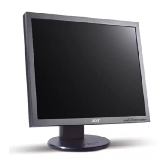
- Page 1 Acer B173 Service Guide Service guide files and updates are available on the CSD web: for more information, Please refer to http://csd.acer.com.tw/ 100% Recycled Paper...
- Page 2 Copyright Copyright © 2003 by Acer Incorporated. All rights reserved. No part of this publication may be reproduced, transmitted, transcribed, stored in a retrieval system, or translated into any language or computer language, in any form or by any means, electronic, mechanical, magnetic, optical, chemical, manual or otherwise, without the prior written permission of Acer Incorporated.
- Page 3 Conventions The following conventions are used in this manual: Screen messages Denotes actual messages that appear on screen Note Gives bits and pieces of additional information related to the current topic. Warning Alerts you to any damage that might result from doing or not doing specific actions.
- Page 4 DIFFERENT part number code to those given in the FRU list of this printed Service Guide. You MUST use the list provided by your regional Acer office to order FRU parts for repair and Service of customer machines.
- Page 5 WARNING: (FOR FCC CERTIFIED MODELS) NOTE: this equipment has been tested and found to comply with the limits for a Class B digital device, pursuant to Part 15 of the FCC Rules. These limits are designed to provide reasonable protection against harmful interference in a residential installation.
- Page 6 PRECAUTIONS Do not use the monitor near water, e.g. near a bathtub, washbowl, kitchen sink, laundry tub, Swimming pool or in a wet basement. Do not place the monitor on an unstable trolley, stand, or table. If the monitor falls, it can injure a person and cause serious damage to the appliance.
- Page 7 SPECIAL NOTES ON LCD MONITORS The following symptoms are normal with LCD monitor and do not indicate a problem. NOTES Due to the nature of the fluorescent light, the screen may flicker during initial use. Turn off the Power Switch and then turn it on again to make sure the flicker disappears. You may find slightly uneven brightness in the screen depending on the desktop pattern you use.
- Page 8 Table of contents Chapter 1 MONITOR FEATURE……………………………………………………………………9 Chapter 2 OPERATING INSTRUTION ………………………………………………………17 Chapter 3 MACHINE ASSEMBLY………………………………………………………………..24 Chapter 4 TROBLE SHOOTING…………………………………………………………………..29 Chapter 5 CONNECTOR INFORMATION…………………………………………………..38 Chapter 6 FRU LIST…………………………………………………………………………………….40 Chapter 7 SCHEMATIC DIAGRAM …………………………………………………………….42...
- Page 9 Chapter 1 Monitor Feature Driving system TFT Color LCD Size 17" Pixel pitch 0.264 mm AUO: 160(H) x 160 (V) degree Viewable angle SAM: 160(H) x 160 (V) degree AUO: 300 cd/m²(typ.) Brightness SAM: 300 cd/m²(typ.) AUO: 800:1(typ.) Contrast Ratio SAM: 1000:1(typ.) LCD Panel Response time...
- Page 10 * Power Switch * MENU / Volume / Volume * AUTO Switch * e-color * Contrast/brightness * Focus * Clock * H.Position * W.Position * Language * OSD Color temperature * OSD Position & Timeout * Auto Config * Input * Information * Reset External Controls :...
- Page 11 Timings The product has 26 memory modes in total. 16 modes are preset and 10 modes are user definable. MODE NO. RESOLUTION 720 x 400 640 x 480 640x480 640 x 480 Dot clock(MHz) 28.321 25.175 30.24 31.5 31.469kHz 31.469kHz 35.0kHz 37.861kHz H-Total ( us )
- Page 12 MODE NO. RESOLUTION 800 x 600 832 x 624 1024 x 768 1024 x 768 Dot clock(MHz) 57.283 48.077kHz 49.72kHz 48.363kHz 56.48kHz H-Total ( us ) 20.80 (1040dots) 20.11(1152 dots) 20.677(1344 dots) 17.71(1328 dots) H-Sync ( us ) 2.400 ( 120 dots) 1.12(64 dots) 2.092(136 dots) 1.81(136 dots)
- Page 13 Monitor Block Diagram DVI_INPUT TO PANEL DVI-D DVI_IIC EEPROM PANEL CONNETER EDID 24C02 SCALER RTD2525LH(RTD2545L) D_SUB15_INPUT(R/G/B/HS/VS/SOG) D-SUB15 D-SUB15_IIC EEPROM EDID 24C02 CONTROL BUS EEPROM 24C16 RTD2021 BUTTON BOARD 5DVCC AUDIO INPUT AUDIO AMP 33VCC TPA6021A4 SPEAKER TO 3.3V POWER BOARD 18DVCC TO 1.8V...
- Page 14 PCB CONDUCTOR VIEW...
- Page 17 Chapter 2 OPERATING INSTRUCTIONS Front Panel Definition This Section defines the front panel User Interface for Led Indictor and Key function. Key Definition: There are six keys defined in this system and described bellows. * Adjusting display settings(User can select the key "AUTO + < + POWER" to enter factory mode) External Controls Power on/off ○...
- Page 18 OSD options OSD options OSD options OSD menu Acer eColor Management: Brightness and Contrast adjusted by Acer eColor Management. User: Brightness and Contrast adjusted by User mode. Focus: This removes any horizontal distortion and makes the picture clear and sharp.
- Page 19 OSD options OSD options Language for EU: English, Deutsch, Espanol, Hollands, Pyccknn, Francais, Italiano, Suomalainen OSD Settings: This changes the position of the OSD window on the screen and the staying time. Input signal: Select either Analog Input or Digital Input video. Information: Information: This shows information about the screen.
- Page 20 This page only be visible in factory mode R,G,B OFFSET : Adjust current RGB cut off level R,G,B GAIN : Adjust current RGB Driver value. SPREAD : Adjust chip set internal frequency spread effect for EMI testing. This page only be visible in factory mode AUTO BURN : Use the chip set internal pattern for hot running monitor panel and inverter.
- Page 21 Acer e-color management Brightness Contrast User Text Standard Graphics Movie...
- Page 22 LED Definition The system equips one dual color (blue/amber) led to indict system status and defined as bellows: LED Color System Status Blue System in normal operation mode Amber System in power-saving mode Dark System in power-off mode LOGO: When the monitor is power on, the LOGO will be showed in the center, and disappear slowly. HOW TO OPTIMIZE THE DOS-MODE Plug and play Plug &...
- Page 23 THIS MONITOR WILL APPEAR TO BE NON-FUNCTIONAL IF THERE IS NO VIDEO INPUT SIGNAL. IN ORDER FOR THIS MONITOR TO OPERATE PROPERLY, THERE MUST BE A VIDEO INPUT SIGNAL. This monitor meets the Green monitor standards as set by the Video Electronics Standards Association(VESA) and/or the United States Environmental Protection Agency (EPA) and The Swedish Confederation Employees (NUTEK).
- Page 24 Chapter 3 Machine assembly This chapter contains step-by-step procedures on how to assemble the monitor for maintenance and trouble shooting NOTE: 1. The screws for the different components vary in size. During the disassembly process, group the screws with the corresponding to avoid mismatch when putting back the components. 2.
- Page 25 Real View: Top View:...
- Page 26 Side View: (unit: mm)
- Page 27 Assembly Procedure 1. Remove 4pcs screws from adjusted stand. 2. Take off the rear cover from LCD. 3. Tear off all the tapes and connectors. 4. Remove 4pcs IO NUTS from joints. 5. Tear off the lamp cables from p/b and the 6.
- Page 28 7. Take off 2pcs screws from b/b and take off it 8. Remove 8pcs screws from m/b and p/b, then from bezel. disconnect them from PCB shielding.
- Page 29 Chapter 4 TROUBLE SHOOTING This chapter provides trouble shooting information for B173 1. No Power No Power Change Power Check CN1 Board Check Short Of Main Board Check Q7,Q8,=1.8V Change Q7,Q8,Q9,U1 Check Change Y1 Y1=24MHz Change U3 or Check U3 Pin...
- Page 30 2. Missing Color Missing Color Change Cable Check VGA Cable Check R70,R73,R78 Change R70,R73,R78 Check CN8 Change U7 or LVDS Signal CN8 Cable or Panel Adjustment Change Panel Check OSD R/G/B Color R/G/B Gain...
- Page 31 3. Always show “NO SIGNEL” “NO SIGNEL” Change Cable Check VGA Cable VGA Check Change U7 C20,C23,R70,R7 Change R70,R73,L5,R73 ,R75 C22,C24...
- Page 32 RTD Tool Only ISP Basic operations Before write 1. Please insure connect LPT cord to PC LPT Port. 2. The correct connection ISP tool to LPT Cord. When write BIOS, Need connect VGA Cord to ISP tool Double Click “RTDTOOL ONLY ISP” procedure。...
- Page 33 Pop out the follow operation surface Click 64K, choose the first bios file (bios file choose from the local disk )
- Page 34 Click 64K~96K,choose the second bios file (the first and the second files save together) Setup file properties Main acts as the main writing file. Second acts as the second writing file. Both acts as both files writing together. 1TO 4 writer acts as 4PCS main boards writing together.
- Page 35 AUTO acts as the pc writing automatically. Erase acts as procedure erased the former bios of monitor. When write PCBANK(WDZV-W1) model bios, use the two files, setup file properties as fellow: 1. Within 64K option, choose no Extend bios file; 2.
- Page 36 Click , go to writing, it is necessary for writing to turn on monitor . During writing, can’t cut off electricity, and VGA cord can’t fall off. After writing OK, will display “CRC OK”. Notices: Writing is not going, will come out the right message “MCU link error”. Analysis: Check: 1.
- Page 37 Notices: warning﹗prohibit from choosing the error position of BIOS file “64K” and “64~~94”, Maybe writing, but writing to display the Chaos of OSD, abnormal.
- Page 38 Chapter 5 Connector Information Phone jack stereo PIN1. AC power cord: CEE22 typed connector PIN2. Audio cable PIN3. Audio: Line-in receptacle 15 pin mini D-Sub connector Signal Green Blue No Pin Ground Ground Red Ground Green Ground Blue +5 V for DDC Ground Ground SDA (DDC Data)
- Page 39 TMDS data2 shield DDC clock DDC data Not connected TMDS data1- TMDS data1+ TMDS data1 shield Ground (return for +5 V and H/V sync) Hot plug detect TMDS data0- TMDS data0+ TMDS data0 shield TMDS clock shield TMDS clock+ TMDS clock-...
- Page 40 Acer office to order FRU parts repair and service of customer machines. NOTE: To scrap or to return the defective parts, you should follow the local government ordinance or regulations on how best to dispose it, or follow the rules set by your regional Acer office on how to return it.
- Page 42 Chapter 7 SCHEMATIC DIAGRAM CONTENTS SCHEMATIC SHEET CONTENT POWER VGA AND TMDS INPUT RTD2525LH AUDIO BLOCK...
- Page 43 5DVCC AUDIO POWER 120/CX20129813/8 C1,EC1,L19 CLOSED CN1 CONN 3x2-R 3DVCC 3DVCC AIC1084/TO252 VOUT 120/CX20129813/8 1K/6 VRMT 10K/6 U1-1 VOUT U1與U1-1共同layout 3DVCC AIC1117/NC 1K/6 1U/8/NC 2005/09/30 VBRI TO252 package DTC144EUA U2-1 AP1117/NC VOUT 2005/09/30 U2與U2-1共同layout 1.8DVCC MCU_VCC AP1084/NC VOUT VOUT SMB/NC SMB/NC DSUB_5V 120/CX201209813/8...
- Page 44 2007.11.22 pin define modify 3DVCC *Co-lay CN3/CN2 note: MENU_O MCU_VCC MCU_VCC SEL_O PWR_O Reset circuit UP_O DOWN_O 10K/6 RIGHT_O 10K/6 LEFT_O 1U/6/NC LED_G 4.7K/6 MMBT3906 MMBT3906 1K/6/NC 7101-E10N NC/TCM810S 82K/6/NC LED_R 4.7K/6 MMBT3906 MCU_VCC HOTKEY_M 5DVCC KEY1 1K/6 MENU_O KEY2 1K/6 SEL_O 1K/6...
- Page 45 PAGE1 VGA 19/CX190T06009/6 INPUT 100/6 0.047u/6 RED+IN DDC_SDA 10pF/6 RED-IN 75/6/F 100/6 0.047u/6 RED+IN RED-IN DDC_SDA GREEN+IN 19/CX190T06009/6 GREEN-IN GREEN+IN 100/6 0.047u/6 IN-H BLUE+IN DSUB_5V BLUE-IN IN-V DSUB_5V 10pF/6 DSUB_5V DDC_SCL GREEN-IN 75/6/F 100/6 0.047u/6 DSUB_DET 19/CX190T06009/6 BLUE+IN 100/6 0.047u/6 DGND 10pF/6 5DVCC...
- Page 46 5DVCC TX0+ R183 R185 2N3904 2N3906 TX0+ TX0- TX0- TX1+ SOT23 SOT23 TX1+ TX1- RTD2525LH/2545LH 0 ohm TX1- TX2+ PANEL_VCC TX2+ TX2- 120/CX201209813/8 AO3415 TX2- TXC+ RTD2545LR with 0 ohm 0.1uF TXC+ TXC- PANEL_VCC TXC- 2007.11.14 modify;reserve for 2545LR R3.3VCC 10K/6 0.1u/6 100UF/16V...
- Page 47 120/CX201209813/8/NC 4.7K/6/NC 0.1u/6/NC 100uF/16V/NC AR14 0/6/NC 10K/6/NC 0/6/NC VOLU 2007/01/16 AGND for EMI VOLUME solution 30K/6/NC DTC144EUA/NC PC AUDIO-IN 2007.11.14 modify AGND 10K/6/NC AL4 120/CX201209813/8/NC R_LINE Z0415 100/6/NC RIN_PC 0.47U/16V/6/NC 1K/6/NC AGND RIN+ SE/~BTL 120/CX201209813/8/NC L_LINE Z0416 100/6/NC LIN_PC 0.47U/16V/6/NC VOLU LIN+ VOLUME...
- Page 48 Button Board MENU SW METALDOME SW METALDOME SW METALDOME RIGHT LEFT AMBER SW METALDOME GREEN 7101-E10N SW METALDOME SW METALDOME GREEN AMBER LED1 KPTB-1612 Front View MENU LEFT RIGHT POWER LED1...
- Page 49 Power Board...