Table of Contents

Related Manuals for Ryobi Airwave C1 RA-NB1832-S


Summary of Contents for Ryobi Airwave C1 RA-NB1832-S
- Page 1 RA-NB1832-s AIRWAVE AIR C1 BRAd NAIlER OpERAtOR's MANUAl ORIgINAl INstRUCtIONs Important! It is essential you read the instructions in this manual before starting and operating this machine. Subject to technical modifications.
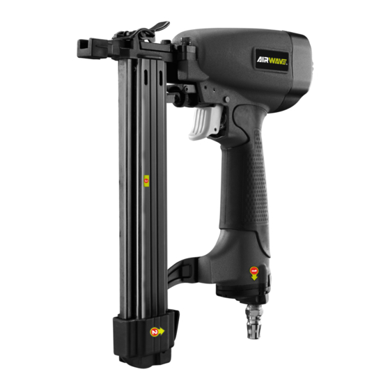
- Page 2 dEsCRIptION 1. Nitto style coupler 2. No mar pad 3. Safety yoke 4. Exhaust cap 5. Air supply 6. Magazine 7. Nails 8. Trigger 9. Depth adjustment knob Fig. 3 10. Flat blade screwdriver 11. Jam release Fig. 1 Fig. 2 Fig.
- Page 3 Fig. 7 Fig. 8 Fig. 9 Fig. 10 Quick Quick connector connector Lubricator Filter Tool compressor Cut-off valve Quick Quick coupler coupler Regulator Air hose (0-8.5 bar) Fig. 11...
-
Page 4: General Safety Rules
comfortable posture while maintaining a secure footing gENERAl sAFEty RUlEs and avoiding awkward or off-balanced postures. The ■ For multiple hazards, read and understand the safety operator should change posture during extended tasks, which can help avoid discomfort and fatigue. instructions before installing, operating, repairing, maintaining, changing accessories on, or working ■... -
Page 5: Information On Mechanical Impact(Vibration)
INFORMAtION ON MEChANICAl IMpACt(VIBRAtION) ■ Repairs shall be carried out only by the manufacturer's authorized agents or by other experts, having due The characteristic vibration values for the fastener driving regard to the information given in the operating tool have been determined in accordance with ISO 8662- instructions. -
Page 6: Residual Risks
trigger using finger pressure. flying objects. In addition, fastener driving tool is fitted with a safety yoke which enables the driving operation to be carried syMBOls out only after the safety yoke of the tool is pressed against a work piece, These tools are marked with an inverted triangle behind the serial number and are Safety alert... -
Page 7: Noise And Vibration
WARNINg Working pressure 4.8 - 8.3 bar (70 - 120 psi) range Ensure the air supply is clean and does not exceed 8.3 bar (120 psi) while operating the product. Too Exhaust Rear adjustable (360°) high an air pressure and unclean air will shorten the Tool weight product's life due to excessive wear, and may be 1.41 kg... -
Page 8: Operation
gauge to be sure it is functioning within the proper range OpERAtION of 4.8 - 8.3 bar (70 - 120 psi). WARNINg NO-MAR pAd See figure 2. Do not use oxygen, combustible gases or bottled gases as a power source for this tool. The tool will explode and The no-mar pad attached to the safety yoke of the tool helps prevent marring and denting when working with cause death or serious injury. - Page 9 3. With the safety yoke of the tool pointed away from you, WARNINg feed a strip of fasteners into the magazine. Be sure the Check for proper functioning by applying the safety yoke fasteners are pointed downward. of the fastener driving tool to a piece of wood or wooden material and actuating the trigger once or twice.
-
Page 10: Setting The Air Pressure
working shift, disconnect the tool from the compressed air Begin testing the depth of drive by driving a test fastener supply and it is recommended to empty the magazine. into the same type of workpiece material used for the actual job. The compressed air connectors of the fastener driving tool and the hoses should be protected against contamination, Drive a test fastener with the air pressure set at 6.2 - 6.5... -
Page 11: General Maintenance
1. Remove fasteners from the tool. WARNINg 2. Pull up on the latch and open the jam release. Do not store tools in a cold weather environment to 3. Insert a flat blade screwdriver into the driving prevent frost or ice formation on the tools’ operating mechanism and push the driver mechanism back, valves and mechanisms that could cause tool failure. - Page 12 WARNINg Do not use any attachments or accessories not recommended by the manufacturer of this tool. The use of attachments or accessories not recommended can result in serious personal injury. lUBRICAtION automatic in-line filter-regulator-lubricator recommended (Fig. 11) as it increases product life and keeps the product in sustained operation.
-
Page 13: Troubleshooting
tROUBlEshOOtINg pROBlEM CAUsE pOssIBlE sOlUtION Loose screws. Tighten screws. Air leak near the top of the tool or in the trigger area. Worn or damaged O-rings or seals. Install overhaul kit. Loose screws. Tighten screws. Air leak near the bottom of the tool. - Page 14 pARts lIst Description Description Description Description Bolt Rubber washer Orientation pin Pusher rod Deflector spring Bolt M3 x 8 Roll pin 2.5 x 18 Pusher head Air deflector Guide sleeve Safety plate Movable magazine Bolt M4 x 35 Safety stand Orientation bar O ring 1.9 x 1.2 Spring washer 4...
- Page 16 techtronic Industries (Australia) pty. ltd. Level 1, 660 Doncaster Road Doncaster, VIC 3108, Australia techtronic Industries New zealand ltd. 18-26 Amelia Earhart Avenue Mangere, Auckland 2022, New Zealand...