Table of Contents
Advertisement
Quick Links
Advertisement
Table of Contents

Related Manuals for Subaru RGX6500/E


Summary of Contents for Subaru RGX6500/E
- Page 1 3ZZ9990578 SUBARU Generator...
- Page 2 Protection Agency) and CARB (California Air Resources Board) emission regulations in the U.S.A. Notice : To the engines/generators exported to and used in the countries other than the U.S.A., warranty service shall be performed by the distributor in each country in accordance with the standard SUBARU engine/generator warranty policy as applicable.
-
Page 3: Table Of Contents
This manual covers operation and maintenance of the SUBARU GENERATOR. This SUBARU GENERATOR can be used for general electrical equipments, appliances, lamps, tools as an AC power source. With regards to DC application, the terminals are used only for charging 12 volt battery. - Page 5 RGX6500, RGX7500 RGX2900, RGX3600, RGX4800 ① ② ⑨ ⑦ ③ ④ ③ ⑦ ⑥ ② ⑥ ⑤ ⑤ ① ⑩ ④ ⑩ ⑨ ⑧ ⑧ ① ② ③ ④ ⑤ ⑥ ⑦ ⑧ ⑨ ⑩...
-
Page 6: Safety Precautions
1. SAFETY PRECAUTIONS Please make sure you review each precaution carefully. Pay special attention to statement preceded by the following words. DANGER “DANGER” indicates a possibility of death or serious injury if instructions are not followed. WARNING “WARNING” indicates a strong possibility of severe personal injury or loss of life if instructions are not followed. - Page 7 WARNING If wet, wipe and dry it well before starting. Do not pour water directly over the generator, nor wash it with water. WARNING Be extremely careful that all necessary electrical grounding procedures are followed during each and every use. Failure to do so can be fatal.
-
Page 8: Specifications
Safety device type Fuse-less circuit breaker Model EX17D EX21D EX27D EX35D EX40D Type SUBARU, Air-cooled, 4-stroke, OHC, Gasoline Engine Displacement mL (cu.in.) 169 (10.31) 211 (12.88) 265 (16.17) 404 (24.65) Fuel Automotive Unleaded Gasoline Fuel Tank Capacity L (U.S.gal) 11.2 (3.0) 22.0 (5.8)... -
Page 9: Components
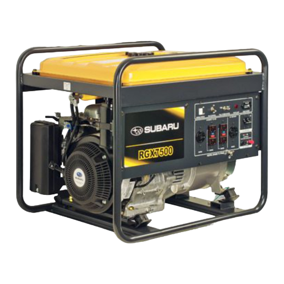
3. COMPONENTS RGX2900, RGX3600, RGX4800 Fuel gauge Tank cap Fuel strainer Control panel ( Fuel valve ) Recoil starter handle Engine switch Recoil starter Oil gauge (oil filler) Oil drain plug Fuel tank Spark plug cap Choke lever Air cleaner Muffler cover Exhaust outlet - 4 -... - Page 10 RGX6500, RGX7500 Tank cap Fuel gauge Control panel Fuel strainer (Fuel valve) Engine switch Recoil starter handle Oil gauge (oil filler) Recoil starter Oil drain plug Fuel tank Choke lever Spark plug cap Air cleaner Muffler cover Exhaust outlet - 5 -...
- Page 11 CONTROL PANEL RGX2900, RGX3600, RGX4800 (RGX4800) (w/Starter motor) Key switch AC receptacle 20A AC receptacle 30A AC receptacle 30A Pilot lamp Full power switch Hour meter Engine switch AC circuit breaker DC output DC circuit AC breaker Earth ( ground ) terminal breaker terminal...
- Page 12 RGX6500, RGX7500 (RGX6500, 7500 w/Starter motor) Key switch Idel control Full power switch Pilot lamp Hour meter switch Engine switch AC receptacle AC circuit breaker DC circuit breaker AC receptacle DC output terminal Earth (ground) AC receptacle terminal - 7 -...
-
Page 13: Pre-Operation Checks
4. PRE-OPERATION CHECKS CHECK ENGINE OIL Before checking or refilling oil, be sure Oil filler cap generator is located on stable and level (Oil gauge) surface with engine stopped. ■ Remove oil filler cap and check the engine oil level. ■... - Page 14 CHECK ENGINE FUEL. WARNING ■ Do not refuel while smoking or near open flame or other such potential fire hazards. Otherwise fire accident may occur. NOTE : Fuel filter screen THIS ENGINE IS CERTIFIED TO OPERATE Fuel tank cap ON AUTOMOTIVE UNLEADED GASOLINE. ■...
- Page 15 CHECKING COMPONENT PARTS Check following items before starting engine: ■ Fuel leakage from fuel hose, etc. ■ Bolts and nuts for looseness. ■ Components for damage or breakage. ■ Generator not resting on or against any adjacent wiring. CHECK GENERATOR SURROUNDINGS WARNING Make sure you review each warning in order to prevent fire hazard.
- Page 16 WARNING Death, personal injury and/or property damage may occur unless instructions are followed carefully. ■ Use battery of recommended capacity. ■ Turn the starter switch to the “STOP” position when mounting or dismounting battery. When mounting battery, connect the positive (+) cable first and then the negative (-) cable to the battery.
-
Page 17: Operating Procedures
5. OPERATING PROCEDURES STARTING THE GENERATOR [ CAUTION ] Check the oil level before each operations as outlined by the article "CHECK ENGINE OIL" (a) Turn the Engine switch to the position "ON". (b) Turn the AC circuit breaker to the position "OFF". - Page 18 (e) Pull the starter handle slowly until passing the compression point (resistance will be felt), then return the handle to its original position and pull briskly. ■ If the engine fails to start after several attempts, repeat above procedures with choke lever returned to "OPEN" position.
- Page 19 USING ELECTRIC POWER WARNING ■ Make sure that the appliance is switched OFF before connecting it to the generator. ■ Do not move the generator while it is running. ■ Be sure to ground the generator if the connected appliance is grounded.
- Page 20 Stop the generator immediately, check the appliance and / or generator for overloading or detect and have repaired as necessary by SUBARU Industrial Power Products dealer or service shop. [ CAUTION ] The duplex 120V receptacle is protected by a GFCI (Ground Fault Circuit Interrupter).
- Page 21 (d) Check and confirm whether circuit breaker position is “ ON ”. (e) Turn on the switch of the appliance. GFCI RECEPTACLE After starting the engine, check the GFCI for proper functioning by the following test procedure. ■ Push blue TEST button, The red RESET button will pop out exposing the word TRIP.
- Page 22 FULL POWER SWITCH (Except RGX2900) 1 2 0 V Select the voltage using the FULL 2 4 0 V 1 2 0 V POWER SWITCH in accordance with the electrical appliance. Refer to TABLE 2. [ CAUTION ] Change the FULL POWER SWITCH after turning the AC circuit breaker to “OFF”.
- Page 23 IDLE CONTROL SWITCH (Except RGX2900) IDLE CONTROL SWITCH automatically reduces engine speed when load is OFF, and automatically increases engine speed to rated r.p.m. when load is ON. IDLE CONTROL SWITCH provides fuel economy and low noise operation at no-load running.
- Page 24 (2) DC APPLICATION The DC terminal is used only for charging Black 12 volt batteries. It provides up to 12V-8.3A (100W) of maximum power. CONNECTION OF CABLE : ■ Connect positive (red) terminal on generator to positive (+) terminal on battery.
- Page 25 STOPPING THE GENERATOR (a) Turn off the power switch of the electric equipment and unplug the cord from receptacle of the generator. (b) Turn the AC circuit breaker to the “OFF” position. (c) Allow the engine about 3 minutes to cool down at no-load before stopping.
-
Page 26: Wattage Information
6.WATTAGE INFORMATION Some appliances need a “surge” of energy when starting. This means that the amount of electrical power needed to start the appliance may exceed the amount needed to maintain its use. Electrical appliances and tools normally come with a label indicating voltage, cycles / Hz, amperage (amps) and electrical power needed to run the appliance or tool. - Page 27 VOLTAGE DROP IN ELECTRIC EXTENSION CORDS When a long electric extension cord is used to connect an appliance or tool to the generator, a certain amount of voltage drop or loss occurs in the extension cord which reduces the effective voltage available for the appliance or tool. The chart below has been prepared to illustrate the approximate voltage loss when an extension cord of 300 feet (approx.
-
Page 28: Spark Arrester
7. SPARK ARRESTER In a dry or wooded area, it is recommendable to use the product with a spark arrester. Some areas require the use of a spark arrester. Please check your local laws and regulations before operating your product. The spark arrester must be cleaned regularly to keep it functioning as designed. -
Page 29: Maintenance Schedule
8. MAINTENANCE SCHEDULE MAINTENANCE, REPLACEMENT, OR REPAIR OF THE EMISSION CONTROL DEVICES AND SYSTEMS MAY BE PERFORMED BY ANY NONROAD ENGINE REPAIR ESTABLISHMENT OR INDIVIDUAL. DAILY INSPECTION Before running the generator, check the following service items: Enough gasoline Excessive vibration,noise Enough clean engine oil Loose or broken bolts and nuts Leakage of gasoline and engine oil... - Page 30 Periodic Maintenance Schedule table Every Every Every Every Every Maintenance Items 8 hours 50 hours 200 hours 500 hours 1000 hours (Daily) (Weekly) (Monthly) Clean generator and check bolt and nuts ● (Daily) ● (Daily) Check for leakage from hoses and fi tting Check and refi...
-
Page 31: How-To" Maintenance
9. ”HOW-TO” MAINTENANCE ENGINE OIL CHANGE ■ Change engine oil every 100 hours. (For new engine, change oil after 20 hours.) (a) Drain oil by removing the drain plug and the oil filler cap while the engine is Oil drain plug warm. - Page 32 HIGH ALTITUDE ENGINE OPERATION ■ Please have an authorized SUBARU Industrial Power Products service dealer modify this engine if it is to be run continuously above 5,000 feet (1,500 meters). Failure to do so, may result in poor engine performance, spark plug fouling, hard starting, and increased emissions.
- Page 33 CHECKING CARBON BRUSH (RGX6500, 7500) If the brush become excessively worn, its contact pressure with the slip ring changes BRUSH HOLDER and causes a roughened surface on the slip ring, resulting in irregular generator performance. Check the brush every 500 hours or if 0.6 to 0.2 in.
-
Page 34: Preparation For Storage
10. PREPARATION FOR STORAGE The following procedures should be followed prior to storage of your generator for periods of 6 months or longer. ■ Drain fuel from fuel tank carefully by disconnecting the fuel line. Gasoline left in the fuel tank will eventually deteriorate making engine- starting difficult. -
Page 35: Troubleshooting
When generator engine fails to start after several attempts, or if no electricity is available at the output socket, check the following chart. If your generator still fails to start or generate electricity, contact your nearest SUBARU Industrial Power Products dealer or service shop for further information or corrective procedures. -
Page 36: Wiring Diagram
12. WIRING DIAGRAM RGX2900 (60Hz-120V) ENGINE CONT.BOX Wiring color code : Black Oil sensor Blk/W : Black/White : Blue LBlu : Light blue Engine switch : Brown Ignition coil Brn/W : Brown/White : Green Grn/W : Green/White : Orange Spark plug : Gray : Red : White... - Page 37 RGX4800 (60Hz-120/240V) ENGINE CONT.BOX Wiring color code Oil sensor : Black Engine switch Blk/W : Black/White : Blue Ignition coil LBlu : Light blue : Brown Brn/W : Brown/White : Green Spark plug Grn/W : Green/White LBlu Idle : Orange Idle control switch control unit...
- Page 38 RGX6500,7500 (60Hz-120/240V) Wiring color code : Black Blk/W : Black/White : Blue Spark plug LBlu : Light Blue : Brown Brn/W : Brown/White IG COIL : Green Grn/W : Green/White LGrn : Light Green : Orange : Gray : Red : White : Yellow Earth...
- Page 39 RGX6500,7500 [w / Starter motor] (60Hz-120/240V) Wiring color code : Black Blk/W : Black/White Spark plug : Blue LBlu : Light Blue : Brown Brn/W : Brown/White IG COIL : Green Grn/W : Green/White LGrn : Light Green : Orange : Gray : Red : White...
- Page 41 ISSUE EMD-GU7220 PRINTED IN JAPAN June 2011...