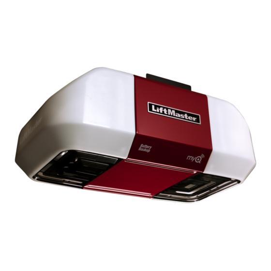
Chamberlain 8587WL Manual
Chain drive
Hide thumbs
Also See for 8587WL:
- Manual (125 pages) ,
- Owner's manual (55 pages) ,
- User manual (36 pages)
Advertisement
Quick Links
Wi-Fi
Garage Door Opener
®
Chain Drive Models 8587W and 8587WL
FOR RESIDENTIAL USE ONLY
LiftMaster
300 Windsor Drive
Oak Brook, IL 60523
•
Please read this manual and the safety materials
carefully!
•
The door WILL NOT CLOSE unless the Protector
System
is connected and properly aligned.
®
•
Periodic checks of the garage door opener are
required to ensure safe operation.
•
This garage door opener is ONLY compatible with
MyQ
and Security+ 2.0
®
•
DO NOT install on a one-piece door if using devices
or features providing unattended close. Unattended
devices and features are to be used ONLY with
sectional doors.
•
Attach warning labels to the location indicated on
label.
Register your garage door opener to receive
updates and offers from LiftMaster
Take a photo of the camera icon
including the points ( ).
Send it in by texting
the photo to 71403 (US)
or visit www.liftmaster.photo (Global)
accessories.
®
Advertisement

Related Manuals for Chamberlain 8587WL


Summary of Contents for Chamberlain 8587WL
- Page 1 Wi-Fi Garage Door Opener ® Chain Drive Models 8587W and 8587WL • Please read this manual and the safety materials FOR RESIDENTIAL USE ONLY carefully! • The door WILL NOT CLOSE unless the Protector System is connected and properly aligned.
-
Page 2: Table Of Contents
Contents Preparation ........3 Assembly . -
Page 3: Preparation
Preparation ® Serial Number Safety Symbol and Signal Word Review This garage door opener has been designed and tested to offer safe service provided it is Write down the following information for future reference: installed, operated, maintained and tested in strict accordance with the instructions and warnings contained in this manual. - Page 4 Preparation Test the Wi-Fi Signal Strength Check the Door Before You Begin You will need: To prevent possible SERIOUS INJURY or DEATH: Wi-Fi enabled smartphone, tablet or laptop ALWAYS call a trained door systems technician if garage door binds, sticks, or Broadband Internet Connection is out of balance.
- Page 5 Preparation Tools Needed 5/32 3/16 5/16 7/16 7/16 9/16...
- Page 6 Preparation Carton Inventory Hardware Assembly Accessories will vary depending on the garage door opener model purchased. Depending Chassis Support Bracket Hardware Chain Spreader Hardware on your specific model, other accessories may be included with your garage door Screw #8-32 x 3/8" (2) Screw #8-32 x 3/8"...
-
Page 7: Assembly
Assembly HARDWARE 1 Attach the Rail to the Garage Door Opener Washered Bolt Lock Nut 5/16"-18x1/2" (Mounted in the (Mounted in the garage garage door opener) door opener) To avoid SERIOUS damage to garage door opener, use ONLY those bolts/fasteners mounted in the top of the opener. - Page 8 Assembly 2 Attach the Chassis Support Bracket 3 Tighten the Chain 1. Loosen the inner nut and lock washer on the trolley threaded shaft. 2. Tighten the outer nut until the chain is a 1/2 inch above the base of the rail at the midpoint of the rail.
-
Page 9: Installation
Installation IMPORTANT INSTALLATION INSTRUCTIONS To reduce the risk of SEVERE INJURY or DEATH: 1. READ AND FOLLOW ALL INSTALLATION WARNINGS AND INSTRUCTIONS. 9. Install wall-mounted garage door control: 2. Install garage door opener ONLY on properly balanced and lubricated garage within sight of the garage door. - Page 10 Installation 1 Determine the Header Bracket Location OPTIONAL Unfinished CEILING Ceiling MOUNT FOR HEADER Header Wall BRACKET To prevent possible SERIOUS INJURY or DEATH: Vertical Centerline of Garage Door Header bracket MUST be RIGIDLY fastened to structural support on header Structural Supports wall or ceiling, otherwise garage door might NOT reverse when required.
- Page 11 Installation OPTION B 2 Install the Header Bracket CEILING INSTALLATION 1. Extend the vertical centerline onto the ceiling as shown. You can attach the header bracket either to the wall above the garage door, or to the 2. Center the bracket on the vertical mark, no more than 6" (15 cm) from the wall. ceiling.
- Page 12 Installation 3 Attach the Rail to the Header Bracket 4 Position the Garage Door Opener 1. Align the rail with the header bracket. Insert the clevis pin through the holes in the header bracket and rail. Secure with the ring fastener. NOTE: Use the packing material as a protective base for the garage door opener.
- Page 13 Installation 5 Hang the Garage Door Opener HARDWARE To avoid possible SERIOUS INJURY from a falling garage door opener, fasten it Lock Washer 5/16" Hex Bolt 5/16"- 18x7/8" Nut 5/16"-18 SECURELY to structural supports of the garage. Concrete anchors MUST be used if installing ANY brackets into masonry.
- Page 14 Installation 6 Install the Light Bulbs 7 Attach the Emergency Release Rope and Handle To prevent possible OVERHEATING of the end panel or light socket: To prevent possible SERIOUS INJURY or DEATH from a falling garage door: Use ONLY A19 incandescent (100W maximum) or compact fluorescent (26W If possible, use emergency release handle to disengage trolley ONLY when maximum) light bulbs.
- Page 15 Installation 8 Install the Door Bracket Metal, insulated or light weight factory reinforced doors: Drill 3/16" fastening holes. Secure the door bracket using the self-threading screws. (Figure 3) Wood Doors: Use top and bottom or side to side door bracket holes. Drill 5/16” holes through Fiberglass, aluminum or lightweight steel garage doors WILL REQUIRE reinforcement the door and secure bracket with 5/16"-18 x 2"...
- Page 16 Installation 9 Connect the Door Arm to the Trolley HARDWARE IMPORTANT: The groove on the straight door arm MUST face away from the curved door arm. Clevis Pin 5/16" x 1-1/4" Hex Bolt 5/16"-18 x 7/8" 1. Close the door. Disconnect the trolley by pulling the emergency release handle. Lock Washer 5/16"...
-
Page 17: Install The Door Control
Install the Door Control 1 Install the Door Control 1. Strip 7/16" (11 mm) of insulation from one end of the wire and separate the wires. 2. Connect one wire to each of the two screws on the back of the door control. The wires can be connected to either screw. - Page 18 Install the Door Control 2 Wire the door control to the garage door opener 3 Attach the warning labels HARDWARE 1. Attach the entrapment warning label on the wall near the door control with tacks or staples. Insulated Staple 2. Attach the manual release/safety reverse test label in a visible location on the (Not Shown) inside of the garage door.
-
Page 19: Install The Protector System
® Install the Protector System Introduction Be sure power is NOT connected to the garage door opener BEFORE installing the safety reversing sensor. To prevent SERIOUS INJURY or DEATH from closing garage door: Correctly connect and align the safety reversing sensor. This required safety device MUST NOT be disabled. - Page 20 ® Install the Protector System OPTION B 1 Install the Safety Reversing Sensors WALL INSTALLATION If additional clearance is needed an extension bracket (not provided) or wood blocks can HARDWARE be used. Make sure each bracket has the same amount of clearance so they will align correctly.
- Page 21 ® Install the Protector System OPTION C FLOOR INSTALLATION 2 Wire the Safety Reversing Sensors Use an extension bracket (not provided) or wood block to raise the sensor bracket if PRE-WIRED INSTALLATIONS: If your garage already has wires installed for the safety needed.
- Page 22 ® Install the Protector System OPTION B PRE-WIRED INSTALLATION Pre-installed Safety reversing wires 1. Cut the end of the safety reversing sensor wire, making sure there is enough wire 7/16" sensor wires (11 mm) to reach the pre-installed wires from the wall. 2.
-
Page 23: Power
Power 1 Connect Power THERE ARE TWO OPTIONS FOR CONNECTING POWER: OPTION A TYPICAL WIRING 1. Plug in the garage door opener into a grounded outlet. 2. DO NOT run garage door opener at this time. TYPICAL WIRING To prevent possible SERIOUS INJURY or DEATH from electrocution or fire: Be sure power is NOT connected to the opener, and disconnect power to circuit BEFORE removing cover to establish permanent wiring connection. - Page 24 Power 2 Ensure the Safety Reversing Sensors are Aligned IF THE AMBER LED ON THE SENDING SENSOR IS NOT GLOWING: 1. Make sure there is power to the garage door opener. The door will not close if the sensors have not been installed and aligned 2.
-
Page 25: Adjustments
Adjustments Introduction PROGRAMMING BUTTONS The programming buttons are located on the left side panel of the garage door opener and are used to program the travel. While programming, the UP and DOWN buttons can be used to move the door as needed. PROGRAMMING BUTTONS Without a properly installed safety reversal system, persons (particularly small UP Button...