Table of Contents
Advertisement
Quick Links
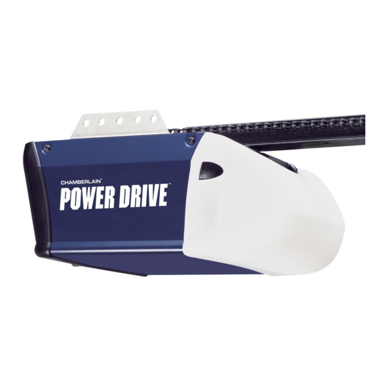
1/2 hp Chain Drive
Garage Door Opener
FOR RESIDENTIAL USE ONLY
. .
Write down the following information
for future reference:
Serial Number:
Date of Purchase:
®
PD210 • PD212D •
PD300 • LW2000 •
HD200D • 248730
There are two types of garage door openers pictured.
Yours may appear slightly different.
■ Please read this manual and the enclosed safety materials carefully!
■ Fasten the manual near the garage door after installation.
■ The door WILL NOT CLOSE unless the Protector System
properly aligned.
■ Periodic checks of the garage door opener are required to ensure safe
operation.
■ The model number label is located on the front panel of your garage
door opener.
Preparation .............................. 1-4
Assembly ................................. 5-9
Installation ............................ 10-19
Install the Door Control ............. 20-21
Power .................................. 26-27
Adjustments .......................... 28-30
Operation.................................. 31
Using Your Garage Door Opener ...... 32
Door Control .............................. 32
To Open the Door Manual .............. 33
Care of Your Opener ..................... 33
PD610D • PD612D •
Having a Problem? ...................... 34
HD400D • LW3000
Diagnostic Chart ......................... 35
Programming ......................... 36-37
The Remote Control Battery ............ 38
Accessories ............................... 39
Warranty .............................. 40-41
Repair Parts .......................... 42-43
®
is connected and
CONTENTS
®
...... 22-25
www.chamberlain.com
The Chamberlain Group, Inc.
845 Larch Avenue
Elmhurst, Illinois 60126-1196
Advertisement
Table of Contents

Related Manuals for Chamberlain POWER DRIVE PD300


Summary of Contents for Chamberlain POWER DRIVE PD300
-
Page 1: Table Of Contents
■ Periodic checks of the garage door opener are required to ensure safe for future reference: operation. ■ The model number label is located on the front panel of your garage Serial Number: door opener. www.chamberlain.com The Chamberlain Group, Inc. Date of Purchase: 845 Larch Avenue Elmhurst, Illinois 60126-1196... -
Page 2: Preparation
Preparation Safety Symbol and Signal Word Review Check the Door This garage door opener has been designed and tested to offer safe service provided it is installed, operated, maintained and tested in strict accordance with the instructions and warnings contained in this manual. - Page 3 Preparation Additional Items You May Need: Tools Needed Survey your garage area to see if you will need any of the following items: (2) 2X4 PIECES OF WOOD May be used to fasten the header bracket to the structural supports. Also used to position the garage door opener during installation and for testing the safety reversing sensors.
- Page 4 Preparation Carton Inventory Models Your garage door opener is packaged in one carton which contains the motor unit and all parts LW2000, Other illustrated below. Accessories vary depending on the garage door opener model purchased. Depending HD200D, Models PD300, on your model, other accessories may be included with your garage door opener. Instructions for these accessories will be attached to the accessory and are not included in this manual.
- Page 5 Preparation Hardware Inventory ASSEMBLY HARDWARE INSTALLATION HARDWARE Self-Threading Screw Bolt Bolt Lag Screw 5/16"-9x1-5/8" (4) 1/4"-14x5/8" (2) 1/4"-20x1-3/4" Clevis Pin 5/16"x1-1/2" Clevis Pin 5/16"x1" Clevis Pin 5/16"x1-1/4" Threaded Shaft Carriage Bolt Wing Nut 1/4"-20 (2) Hex Bolt 5/16"-18x7/8" (4) 1/4"-20x1/2" (2) Lock Washer 5/16"-18 (5) Master Link...
-
Page 6: Assembly
Assembly To garage STEP 1 Assemble the rail and trolley door opener (TO MOTOR UNIT) “U” Bracket To prevent INJURY from pinching, keep hands and fingers away from the joints while assembling the Outer Trolley rail. To avoid installation difficulties, do not run the garage door opener until instructed to do so. Inner Trolley The front rail has a cut out “window”... - Page 7 Assembly STEP 2 Fasten the rail to the motor unit Hex Screws 8-32x7/16 Bolts To avoid SERIOUS damage to garage door opener, use ONLY those bolts/fasteners mounted in the “U” Bracket Bolt top of the opener. 1/4"-20x1-3/4" Cover Protection Bolt Hole To avoid possible SERIOUS INJURY to fingers: Securely attach chain spreader.
- Page 8 Assembly STEP 3 Install the idler pulley CORRECT Rail Tab 1. Lay the chain/cable beside the rail, as shown. Grasp the end with the cable loop and pass approximately 12" (30 cm) of cable through the window. Allow it to hang until Assembly Step 4. 2.
- Page 9 Assembly STEP 4 Install the chain 1. Pull the cable around the idler pulley and toward the trolley. 2. Connect the cable to the retaining slot on the trolley. (a) a. Push pins of master link bar through cable link and trolley slot. Sprocket b.
- Page 10 Assembly Trolley STEP 5 Tighten the chain Outer Lock Threaded Washer Shaft To Tighten Outer Nut 1. Spin the inner nut and lock washer down the trolley threaded shaft, away from the trolley. 2. To tighten the chain, turn the outer nut in the direction shown. 3.
-
Page 11: Installation
Installation IMPORTANT INSTALLATION INSTRUCTIONS To reduce the risk of SEVERE INJURY or DEATH: 1. READ AND FOLLOW ALL INSTALLATION WARNINGS AND INSTRUCTIONS. 9. Install wall-mounted garage door control: 2. Install garage door opener ONLY on properly balanced and lubricated garage door. An •... - Page 12 Installation STEP 1 Determine the header bracket location OPTIONAL CEILING MOUNT Header Wall FOR HEADER BRACKET Vertical Centerline of Garage Door Structural Supports Unfinished Ceiling To prevent possible SERIOUS INJURY or DEATH: • Header bracket MUST be RIGIDLY fastened to structural support on header wall or ceiling, otherwise garage door might NOT reverse when required.
- Page 13 Installation STEP 2 Install the header bracket OPTION B CEILING INSTALLATION You can attach the header bracket either to the wall above the garage door, or to the ceiling. Follow the 1. Extend the vertical centerline onto the ceiling as shown. instructions which will work best for your particular requirements.
- Page 14 Installation STEP 3 Attach the rail to the header bracket STEP 4 Position the garage door opener 1. Align the rail with the header bracket. Insert the clevis pin through the holes in the header bracket and rail. Secure with the ring fastener. NOTE: Use the packing material as a protective base for the garage door opener.
- Page 15 Finished (not provided) Ceiling Lag Screw Lag Screw Finished Ceiling Unfinished Ceiling 5/16"- 5/16"- 9x1-5/8" 9x1-5/8" Hex Bolt 5/16"- 18x7/8" Lock Washer 5/16"-18 (not provided) HARDWARE Nut 5/16"-18 Lag Screw 5/16"-9x1-5/8" Lock Washer 5/16"-18 Nut 5/16"-18 Hex Bolt 5/16"- 18x7/8"...
- Page 16 Installation STEP 6 Install the light bulbs STEP 7 Attach the emergency release rope and handle To prevent possible SERIOUS INJURY or DEATH from a falling garage door: To prevent possible OVERHEATING of the endpanel or light socket: • If possible, use emergency release handle to disengage trolley ONLY when garage door is DO NOT use short neck or specialty light bulbs.
- Page 17 Installation Metal or light weight doors using a vertical angle iron brace between the door panel support STEP 8 Install the door bracket and the door bracket: • Drill 3/16" fastening holes. Secure the door bracket using the two self threading screws. (Figure 2) •...
- Page 18 Installation STEP 8 Install the door bracket (continued) Header Wall OPTION B 2x4 Support (Finished Ceiling) ONE-PIECE DOORS 1. Center the door bracket on the top of the door, in line with the header bracket as shown. Header Bracket 2. Mark either the left and right, or the top and bottom holes. Metal Doors: •...
- Page 19 Installation STEP 9 Connect the door arm to the trolley CORRECT INCORRECT Installation will vary according to the garage door type. Follow the instructions which apply to your door. Straight Straight Door Curved Door Arm OPTION A Curved SECTIONAL DOORS Door Door (Groove...
- Page 20 Installation STEP 9 Connect the door arm to the trolley (continued) HARDWARE OPTION B ONE-PIECE DOORS 1. Assemble the door arm, Figure 1: Clevis Pin 5/16"x1" Clevis Pin 5/16"x1-1/4" IMPORTANT: The groove on the straight door arm MUST face away from the curved door arm. Hex Bolt 5/16"-18x7/8"...
-
Page 21: Install The Door Control
Installation STEP 10 Install the door control Connect the door control wires: 1. Strip 7/16" (11 mm) of insulation from one end of bell wire and connect to the two screw terminals on back of door control by color: white wire to WHT (1) and white/red wire to the RED (2). - Page 22 Installation STEP 11 Wire the door control to the garage door opener STEP 12 Attach the warning labels 1. Attach the entrapment warning label on the wall near the door control with tacks or staples. 2. Attach the manual release/safety reverse test label in a visible location on the inside of the HARDWARE garage door.
-
Page 23: Install The Protector System
Installation ® STEP 13 Install the Protector System HARDWARE Carriage Bolt Wing Nut 1/4"-20x1/2" 1/4"-20 Be sure power is NOT connected to the garage door opener BEFORE installing the safety reversing sensor. The safety reversing sensors can be attached to the door track, the wall, or the floor. The sensors should To prevent SERIOUS INJURY or DEATH from closing garage door: be no more than 6 inches (15 cm) above the floor. - Page 24 Installation ® OPTION C STEP 13 Install the Protector System (continued) FLOOR INSTALLATION OPTION B WALL INSTALLATION Use an extension bracket (not provided) or wood block to raise the sensor bracket if needed. 1. Carefully measure the position of both sensor brackets so they will be the same distance from If additional clearance is needed an extension bracket (not provided) or wood blocks can be used.
- Page 25 Installation STEP 14 Wire the Safety Reversing Sensors Staple If your garage already has wires installed for the safety reversing sensors, proceed to page 25. HARDWARE Insulated Staple 7/16" (11 mm) (Not Shown) OPTION A INSTALLATION WITHOUT PRE-WIRING 1. Run the wire from both sensors to the garage door opener. Attach the wire to the wall and ceiling with the staples.
- Page 26 Installation STEP 14 Wire the Safety Reversing Sensors (continued) Pre-installed Safety reversing OPTION B PRE-WIRED INSTALLATION wires 7/16" sensor wires (11 mm) 1. Cut the end of the safety reversing sensor wire, making sure there is enough wire to reach the pre-installed wires from the wall.
-
Page 27: Power
Installation STEP 15 Connect power THERE ARE TWO OPTIONS FOR CONNECTING POWER: OPTION A TYPICAL WIRING 1. Plug in the garage door opener into a grounded outlet. 2. DO NOT run garage door opener at this time. To prevent possible SERIOUS INJURY or DEATH from electrocution or fire: OPTION B •... - Page 28 Installation STEP 16 Ensure the safety reversing sensors are aligned IF THE AMBER LED ON THE SENDING SENSOR IS NOT GLOWING: 1. Make sure there is power to the garage door opener. The door will not close if the sensors have not been installed and aligned correctly. 2.
-
Page 29: Adjustments
Adjustments Step 1 Adjust the UP and DOWN Travel Limits HOW AND WHEN TO ADJUST THE LIMITS • If the door does not open completely but opens at least five feet (1.5 m): Increase up travel. Turn the UP limit adjustment screw clockwise. One turn equals 2" (5 cm) of travel. - Page 30 Adjustments Step 2 Adjust the Force HOW AND WHEN TO ADJUST THE FORCES 1. Test the DOWN (close) force Grasp the door bottom when the door is about halfway through DOWN (close) travel. The door should reverse. Reversal halfway through down travel does not guarantee reversal on a 1- 1/2"...
- Page 31 Adjustments ® STEP 3 Test the Safety Reversal System STEP 4 Test the Protector System Without a properly installed safety reversal system, persons (particularly small children) could be Without a properly installed safety reversing sensor, persons (particularly small children) could be SERIOUSLY INJURED or KILLED by a closing garage door.
-
Page 32: Operation
Operation IMPORTANT SAFETY INSTRUCTIONS To reduce the risk of SEVERE INJURY or DEATH: 1. READ AND FOLLOW ALL WARNINGS AND INSTRUCTIONS. 10. Safety reversal system MUST be tested every month. Garage door MUST reverse on 2. ALWAYS keep remote controls out of reach of children. NEVER permit children to operate or contact with 1-1/2"... -
Page 33: Using Your Garage Door Opener
Operation Using Your Garage Door Opener Using the Wall-Mounted Door Control Your Security+ ® opener and hand-held remote control have been factory-set to a matching code which Door Control Button changes with each use, randomly accessing over 100 billion new codes. Your opener will operate with Press the lighted push button to open or close the door. -
Page 34: To Open The Door Manual
Operation To Open the Door Manually Care of Your Opener LIMIT AND FORCE ADJUSTMENTS Weather conditions may cause some minor changes in door operation requiring some re-adjustments, particularly during the first year of operation. Pages 28 and 29 refer to the limit and force adjustments. Only a screwdriver is required. -
Page 35: Having A Problem
Operation 4. My door reverses for no apparent reason after fully closing and touching the floor: Repeat Having a Problem? safety reverse test after adjustments to force or travel limits. The need for occasional adjustment for the force and limit settings is normal. Weather conditions in particular can affect Sending Eye Bell Wire door travel. -
Page 36: Diagnostic Chart
Operation Diagnostic Chart Diagnostics Located 3 Flashes Symptom: LED is not lit on door control. on Motor Unit Door control or wire Inspect door control/wires for a short (staple in wire), Bell Wire shorted. replace as needed. Disconnect wires at door control, touch wires together. If motor unit activates, Installed replace door control. -
Page 37: Programming
Operation Programming NOTICE: If this Security+ ® garage door opener is operated with a non-rolling code transmitter, the To Erase the Memory technical measure in the receiver of the garage door opener, which provides security against code-theft ERASE ALL REMOTE CONTROLS AND KEYLESS ENTRIES devices, will be circumvented. - Page 38 Operation Programming To change an existing, known PIN If the existing PIN is known, it may be changed by one person without using a ladder. To Add, Reprogram or Change a Keyless Entry PIN 1. Press the four buttons for the present PIN, then press and hold the # button. NOTE: Your new Keyless Entry must be programmed to operate your garage door opener.
-
Page 39: The Remote Control Battery
Operation The Remote Control Battery To prevent possible SERIOUS INJURY or DEATH: • NEVER allow small children near batteries. • If battery is swallowed, immediately notify doctor. To reduce risk of fire, explosion or chemical burn: • Replace ONLY with 3V2032 coin batteries. •... -
Page 40: Accessories
The Garage Door Opener NO access door. sensor installation onto the wall Surge Protector is designed to Includes visor clip. or floor. protect Chamberlain garage door openers against damage from lighting and power surges. Easy to install. SECURITY✚ ® 3-Button Mini-Remote... -
Page 41: Warranty
248730, LW2000 & HD200D The Chamberlain Group, Inc. (“Seller”) warrants to the fi rst retail purchaser of this product, for the residence in The Chamberlain Group, Inc. (“Seller”) warrants to the fi rst retail purchaser of this product, for the residence in... - Page 42 TEN-YEAR MOTOR LIMITED WARRANTY HD400D & LW3000 The Chamberlain Group, Inc. (“Seller”) warrants to the first retail purchaser of this product, for the residence in which this product is originally installed, that it is free from defect in materials and/or workmanship for a period of two years from the date of purchase and that the motor is free from defect in materials and/or workmanship for a period of ten years from the date of purchase.
-
Page 43: Repair Parts
If you are ordering a repair part please have the following information: part number, part name, Control Panel and model number. Single-button Remote 950D Control Address repair parts orders to: The Chamberlain Group, Inc. 3-Button Remote 953D 6050 S. Country Club Rd. Control Tucson, AZ 85706... - Page 44 Grey Wire Drive 18 End Panel for Receiver Logic Board Gear Models PD610D/PD612D/HD400D/LW3000 41D180-1 (Up) Center Limit Models PD210D/PD212D/PD300/LW2000/HD200D/248730 41A5484-1 Yellow Wire Contact Contact Not Shown Motor Shaft Bearing Kit 41A2826 © 2013, The Chamberlain Group, Inc. 114A4254H All Rights Reserved...