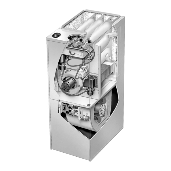
Lennox G26 Series Installation Instructions Manual
Hide thumbs
Also See for G26 Series:
- User manual (54 pages) ,
- Installation instructions manual (31 pages) ,
- User's information manual (6 pages)
Advertisement
Quick Links
Advertisement

Summary of Contents for Lennox G26 Series
- Page 1 *2P1100* *P504228M* Downloaded from ManualsNet.com search engine...
- Page 2 Downloaded from ManualsNet.com search engine...
- Page 3 Downloaded from ManualsNet.com search engine...
- Page 4 NOTE - G26 series units must not be used as a construc tion heater during any phase of construction. Very low re- turn air temperatures, harmful vapors and misplacement of the filters will damage the unit and lower its efficiency.
- Page 5 NOTE - 1/3 and 1/2 hp blower motors are equipped with ei ther four flexible mounting legs or three flexible legs and one rigid leg. The rigid leg is equipped with a shipping bolt and a flat white plastic washer (rather than the rubber mounting grommet used with a flexible mounting leg).
- Page 6 NOTE - The filter door may be shipped in the rack behind the filter. If necessary, remove the filter, retrieve the door and continue with the installation of the rack. NOTE - Be careful not to damage glass fiber insulation. Check for tight seal.
- Page 7 NOTE - For bottom return air, return air duct should be se cured to the unit using rivets or S locks. For side return air, secure return air duct to filter rack using screws. When us ing screws, take care to avoid interference with the filter which may cause improper filtration.
- Page 8 Intake and Exhaust Pip ing Terminations ° ° ° ° NOTE - M inch pipe for G26-50 is 5 feet and 2 elbows of 1.5 inch diameter pipe. NOTE - M inch pipe for G26-75 is 5 feet and 2 elbows of 2 inch diameter pipe.
- Page 9 NOTE - Time is critical at this stage. Do not allow prim er to dry before applying cement. NOTE-Assembly should be completed within 20 sec onds after last application of cement. Hammer blows should not be used when inserting pipe. NOTE - Exhaust piping should be checked carefully to make sure there are no sags or low spots.
- Page 10 NOTE - If winter design temperature is below 32°F (0°C), exhaust piping must be insulated with 1/2 inch (13mm), Armaflex or equivalent when run through unheated space. Do not leave any surface area of exhaust pipe open to out-side air; exterior exhaust pipe must be insu lated with 1/2 inch (13mm) Armaflex or equivalent.
- Page 11 Also, a heating cable may be installed on exhaust piping and termination to prevent freeze-ups. Heating cable installation kit is avail- able from Lennox. See Condensate Piping section for part numbers. NOTE - Care must be taken to avoid recirculation of ex haust back into intake pipe.
- Page 12 Downloaded from ManualsNet.com search engine...
- Page 13 É É É É É É É É É É É É É É É É É É É É Downloaded from ManualsNet.com search engine...
- Page 14 Downloaded from ManualsNet.com search engine...
- Page 15 NOTE - Install a 1/8 inch NPT plugged tap in the field pip ing upstream of the gas supply connection to the unit. The tap must be accessible for test gauge connection. See figure 24. NOTE - Use two wrenches when connecting gas pip ing to avoid transferring torque to the manifold.
- Page 16 NOTE-Capacity given in cubic feet of gas per hour (kilo liters of gas per hour) and based on 0.60 specific gravity gas. The furnace must be isolated from the gas supply system by closing its individual manual shut off valve during any pressure testing of the gas supply system at pressures 1/2 psig (3.48 kPa, 14 inches w.c.).
- Page 17 Downloaded from ManualsNet.com search engine...
- Page 18 Downloaded from ManualsNet.com search engine...
- Page 19 Downloaded from ManualsNet.com search engine...
- Page 20 Downloaded from ManualsNet.com search engine...
- Page 21 White Rodgers 36E Gas Valve - Honeywell VR8205 Gas Valve - White Rodgers 36E Gas Valve - Honeywell VR8205 Gas Valve - NOTE - When unit is initially started, steps 1 through 11 may need to be repeated to purge air from line. NOTE - On initial start-up and when condensate trap is dry, unit may turn itself off and on to allow condensate trap to fill.
- Page 22 Take care to replace pressure tap plug. NOTE - During this test procedure, the unit unit will be over- firing: NOTE - Pressure test adaptor kit (10L34) is available from Lennox to facilitate manifold pressure measurement. Downloaded from ManualsNet.com search engine...
- Page 23 NOTE - Do not secure electrical conduit directly to ducting or structure. NOTE - CFM readings are taken external to unit with a dry evaporator coil, filter installed and without any other acces sories. Burner Flame Downloaded from ManualsNet.com search engine...
- Page 24 NOTE - Unit is polarity sensitive. 120V supply wiring must be installed correctly. Downloaded from ManualsNet.com search engine...
- Page 25 NOTE - Ignitor must be installed on the opposite side of the burner from the metal button protrusions. Screws which attached the ignitor bracket must be installed from the same side as the ignitor and through the brack et to engage in the smaller holes located in the burner. The correct burner orientation is with metal button pro trusions always pointing up.
- Page 26 NOTE - Slow flash equals 1 Hz (one flash per second). Fast flash equals 3 Hz (three flashes per second). Minimum flame sense current = 0.15 microAmps. Downloaded from ManualsNet.com search engine...
- Page 27 Downloaded from ManualsNet.com search engine...
- Page 28 4 SECONDS Downloaded from ManualsNet.com search engine...
- Page 29 Downloaded from ManualsNet.com search engine...
- Page 30 Downloaded from ManualsNet.com search engine...
- Page 31 Downloaded from ManualsNet.com search engine...


