
Related Manuals for Planet BSP-360


Summary of Contents for Planet BSP-360
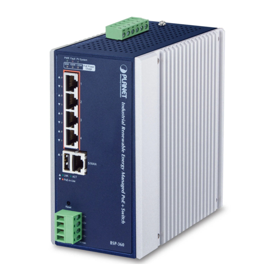
- Page 1 Industrial Renewable Power 5-Port Gigabit Managed Switch/Router with 4-Port 802.3at PoE+ BSP-360 Quick Installation Guide...
- Page 2 Safety Precautions Please read the following before using: 1. All electrical work must be done in accordance with local, and/or international electrical codes. 2. Before installing or using this device, read all instructions and cautionary marking located in (or on) this guide, the controller, the batteries, PV (Photovol- taic) array and any other device used.
-
Page 3: Table Of Contents
Table of Contents 1. Package Contents ..................4 2. Requirements ..................... 5 3. Hardware Introduction ................6 3.1 Front Panel ..................6 3.2 LED Indicators..................7 3.3 Upper Panel ..................8 4. Hardware Installation .................10 5. Web Management ..................16 6. [OPTIONAL] Deployed Devices Monitored via NMS-360 Controller ....18 7. -
Page 4: Package Contents
1. Package Contents Thank you for purchasing PLANET Industrial Renewable Energy Managed PoE Switch/Router, BSP-360. Open the box of the BSP-360 and carefully unpack it. The box should contain the following items: 1 x BSP-360 1 x Quick Installation Guide... -
Page 5: Requirements
2. Requirements PLANET BSP-360 provides a remote login interface for management purposes. The following equipment is necessary for further management: Workstation is installed with Ethernet NIC (Network Interface Card) Choice of Internet browsers includes Windows XP/2003, Vista, Windows 7, Windows 8, Windows 10, Windows 11, MAC OS X, Linux, Fedora, Ubuntu or other platforms compatible with TCP/IP protocols. -
Page 6: Hardware Introduction
3. Hardware Introduction 3.1 Front Panel The front panel of the BSP-360 consists of 5 auto-sensing 10/100/1000Mbps Ethernet RJ45 ports and one USB interface. The LED Indicators are also located on the RJ45 ports of the BSP-360. PWR Alarm PV System... -
Page 7: Led Indicators
3.2 LED Indicators System Color Function Green To indicate BSP-360 has power. Slow To indicate PV < 24V.* Blinks Alarm Fast To indicate battery voltage is ≤ LVD.* Blinks Slow To indicate the system is “Not Charging”. Blinks Green... -
Page 8: Upper Panel
3.3 Upper Panel The upper panel of the BSP-360 consists of one terminal block connector with PV and battery power inputs. Please make sure the V+ & V is connected correctly, Warning and the wire gauge meets the maximum current. - Page 9 Battery In/Out 24V DC Please make sure the V+ & V is connected correctly, Warning and the wire gauge meets the maximum current. 24V DC 1 2 3 4 5 6 Max. Fault Alarm Loading: 24V, 1A Battery DC Input: 24V , 10A Bat.
-
Page 10: Hardware Installation
Please follow the following steps to install the system: Step 1. Installing BSP-360 Place the BSP-360 in a desired location using the wall-mount or Din-rail fixtures. a. Please install the BSP-360 in a proper enclosure or shelter. b. The BSP-360 must be grounded. - Page 11 2. Connect the positive electrode of the battery to the terminal for the positive electrode of the battery on the BSP-360. 3. After the battery is well connected to the BSP-360, the PWR LED will be ON and System LED will slowly blink, and Alarm LED will slowly blink.
- Page 12 2. Connect the positive electrode of the PV panel to the terminal for the posi- tive electrode of the PV panel on the BSP-360. 3. After the PV is well connected to the BSP-360 and providing 24V or above voltage, the System LED will blink fast for battery charge if the battery is not full.
- Page 13 Step 4. Connecting 802.3af/802.3at PoE Device 802.3af/at PoE Device 1. Connect the PoE devices to ports 1~4 on the BSP-360. 2. Check the PoE-in-Use LED. If the network devices such as PoE camera and PoE wireless AP are powered, the PoE-in-use LED will turn ON and Link/Act LED will blink for a successful connection or data receiving.
- Page 14 Step 5. Wiring the DC Outputs Please follow the steps below to insert the power wires for DC power required equipment. 1. Please find the terminal block connector with two DC power outputs shown below: 2. Insert the Positive and Negative DC wires into the V+ and V- terminals, respectively;...
- Page 15 Please ensure the output voltage is correct for remote device. Otherwise, it will damage your remote device. Step 6. Connecting to PC or your remote Ethernet network. Ethernet Switch Monitoring Center BSP-360 After completing the above 6 steps, the BSP-360 is ready for service.
-
Page 16: Web Management
5. Web Management The following shows how to start up the Web Management of the BSP-360. Note the BSP-360 is configured through an Ethernet connection. Please make sure the manager PC must be set to the same IP subnet address. - Page 17 Function Menu Now, you can use the Web management interface to continue the BSP-360 management. Please refer to the user manual for more details. For security reason, please change and memorize the new pass- word after this first setup.
-
Page 18: Optional] Deployed Devices Monitored Via Nms-360 Controller
Note The NMS-360 is used to centrally manage a large number of BSP-360. Therefore, you need to upgrade the BSP-360 firmware before using NMS-360. Please download and use the latest BSP-360 firmware from the website so that setting can be completed smoothly. - Page 19 Step 2. BSP-360: Log in to the BSP-360 Web User Interface and enable both the SNMP and NMS controller functions. Enable “SNMP” Enable “NMS” If you want to use central management, and ONVIF monitoring functions, please refer to the user manual or NMS-360 series related profile.
-
Page 20: Customer Support
7. Customer Support Thank you for purchasing PLANET products. You can browse our online FAQ resource on PLANET web site first to check if it could solve your issue. If you need more support information, please contact PLANET switch support team. -
Page 21: Appendix A: Recommended Use Of The Connected Wires
Appendix A: Recommended Use of the Connected Wires The wire gauges for the current are shown below: Gauge Diameter AWG #16 1.295 10.00 AWG #17 1.143 8.40 AWG #18 1.016 6.40 AWG #19 0.914 5.20 AWG #20 0.813 4.00... -
Page 22: Appendix B: Recommended Settings For Batteries
Appendix B: Recommended Settings for Batteries Use Lead-acid battery for BSP-360. You could set the Battery type at Battery Management on the web of BSP-360. Use Lithium battery for BSP-360. You could set the Battery type at Battery Management on the web of BSP-360. -
Page 23: Appendix C: Battery Default
Default Charge Board LVD 21.3V Default Charge Board LVR 24.0V Copyright © PLANET Technology Corp. 2022. Contents are subject to revision without prior notice. PLANET is a registered trademark of PLANET Technology Corp. All other trademarks belong to their respective owners.