Table of Contents
Advertisement
Quick Links
Advertisement
Table of Contents

Related Manuals for New Holland N4013HGHW


Summary of Contents for New Holland N4013HGHW
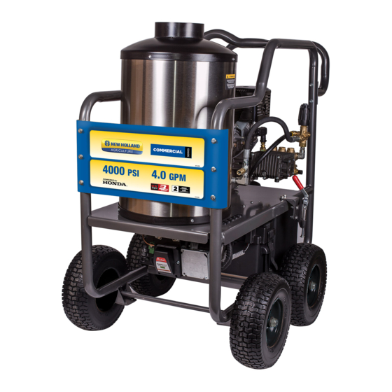
- Page 1 HOT WATER PRESSURE WASHER N4015RAHW N4013HGHW OPERATOR’S MANUAL 85.610.522...
-
Page 2: Table Of Contents
TABLE OF CONTENTS INTRODUCTION Introduction & Identification Numbers .............. 3 IMPORTANT SAFETY WARNINGS Important Safety Warnings & Symbols ............. 4 GENERAL INFORMATION Product Features & Components ............... 7 SET-UP Water Supply ..................... 8 How to Use Nozzles ..................9 OPERATION Pre-Operation Safety &... -
Page 3: Introduction & Identification Numbers
INTRODUCTION & PRODUCT INFO ATTENTION: Read through the complete manual prior to the initial use of your pressure washer. Using the Operator’s manual The operator’s manual is an important part of your pressure washer. It should be read thoroughly before initial use, and referred to often to make sure adequate safety and service concerns are being addressed. -
Page 4: Important Safety Warnings
IMPORTANT SAFETY WARNINGS This is the safety alert symbol. It is used to alert you to potential personal injury hazards. Obey all safety messages that follow this symbol to avoid possible injury or death. DANGER This is indicates a hazard which, if not avoided, will result in serious injury or death. WARNING This indicates a hazard which, if not avoided, will result in a severe injury or property damage. - Page 5 IMPORTANT SAFETY WARNINGS WARNING Serious injury or death may occur from a fire caused by a muffler spark. Serious injury or death may occur if system safety’s are not properly maintained. • A spark arrester must be added to the muffler of this engine when using on land covered with any flammable agricultural crop (hay and grain), and if they are used in or near brush or forested areas.
- Page 6 IMPORTANT SAFETY WARNINGS WARNING Serious injury may occur from touching the gasoline engine, muffler, or heat exchanger. These areas can remain hot for some time after the pressure washer is shutdown. • Never allow any part of your body to contact the gasoline engine, muffler, or heat exchanger. WARNING Serious injury may occur from a pressure washer malfunction or exploding accessories if incorrect system components, attachments, or accessories are used.
-
Page 7: General Information
55 AH AGM deep cycle battery Mounting bracket for truck mounting 3/4”HD Threaded mount axle 13” heavy-duty flat free tires Description N4013HGHW N4015RAHW Pressure Rating 4000 4000 Engine Model Honda GX390 Powerease Displacement 390cc... -
Page 8: Set-Up
SET-UP WATER SUPPLY 1. Select a water supply hose which is a quality grade of the hose measuring at least 3/4” ID and no longer than 50 feet to the water tank. 2. Connect the hose to the inlet of your high pressure pump. Thread the connection together by hand until tight. -
Page 9: How To Use Nozzles
SET-UP Soaper YELLOW GREEN WHITE BLACK HOW TO USE SPRAY TIPS The quick–connect on the nozzle extension allows you to switch between five different quick-connect spray tips. Spray tips can be changed while the pressure washer is running once the spray gun trigger safety lock is engaged. -
Page 10: Operation
OPERATION PRE-OPERATION SAFETY 1. This unit should only be placed on a level surface to ensure proper lubrication for the water pump while operating. Placing the unit on a level surface will also ensure that fuel, oil, and other fluids don’t spill during operation. -
Page 11: Starting The Unit
OPERATION START-UP (COLD WATER) To start your pressure washer for the first time, follow these instructions step-by-step. This starting information also applies if you have let the pressure washer sit idle for at least a day. 1. Make sure the unit is level and placed on solid ground. Ensure the wheels are locked so that it doesn’t move during operation. - Page 12 OPERATION 6. Attach the other end of the high pressure hose to high pressure outlet (“A” on diagram below) on pump. Pull down on collar of quick-connect, slide onto pump and let go of collar. Note that some pumps require the hose to be threaded on.
-
Page 13: Hot Water Operation & Detergent Use
OPERATION HOT WATER OPERATION Now that the unit is running, it is operating as a cold water pressure washer. When you wish to switch to hot water, turn the burner switch to the “ON” position. NOTICE Upon initial start-up, water will begin heating up in approximately 20 seconds. It will reach maximum temperature within 2-1/2 minutes providing that the trigger is continuously pressed down. -
Page 14: Shutting The Unit Down & Storage
OPERATION SHUTTING THE UNIT DOWN 1. Move the burner switch to the “OFF” position. 2. Squeeze the trigger and discharge the water for three minutes to cool the heat exchanger and high pressure hose. Insufficient cool-down periods for the high pressure hose will cause excessive wear and eventual rupture of the hose. -
Page 15: Maintenance
MAINTENANCE SPECIFIC MAINTENANCE ENGINE: The engine instructions that accompany your unit detail specific procedures for maintenance of the engine. Following the engine manufacturer’s recommendations will extend the engine’s life and ensure the best possible performance. PUMP: Change the pump oil after the first 50 hours of operation. After the initial change, every 3 months or 250 hour intervals are recommended. -
Page 16: Maintenance Schedule
MAINTENANCE MAINTENANCE SCHEDULE PROCEDURE DAILY 3 MONTHS 6 MONTHS 9 MONTHS 12 MONTHS Check engine oil level Change engine oil ***** Check water pump oil level Change water pump oil Oil leak inspection Fuel leak inspection Water leak inspection Hose inspection Water inlet screen inspection Check fuel filter Replace fuel filter... -
Page 17: Unit Breakdown
UNIT BREAKDOWN BREAKDOWN ITEM PART NUMBER DESCRIPTION QTY. 85.600.220 Frame Engine, 13 HP, 389cc (GX390 2QNR) 85.578.150 Engine, 420cc Powerease Engine 59.000.000 Hot Water Coil Assy, 4 GPM... -
Page 18: Parts Reference List
PARTS REFERENCE LIST ITEM PART NUMBER DESCRIPTION QTY. 59.000.117 Top Cap Coil Insulation 59.000.116 Bottom Coil Insulation 85.205.064 5000 PSI Gun & Wand Assy 85.609.039 10 Gallon Fuel Tank 85.603.003 Battery Package (Battery, Case, and Cover) Engine Charger 18A Engine Charger (For GX390) 85.600.220-13 Hose Reel Bracket 59.000.001... -
Page 19: Burner Breakdown
Section: Replacement Parts Replacement Parts BURNER BREAKDOWN Illustration # Description Illustration # Description DC Motor Illustration Illustration Igniter Assy with baseplate Blower Wheel Description Part# Description Part# Igniter only Coupling DC Motor Escutcheon Plate Air Tube Ass’y Air Guide Electrode Kit over 3- 5/8 ” Blower Wheel Flange Mounting Gasket Burner Housing - Black... -
Page 20: Burner Breakdown
PUMP BREACKDOWN (EZ4040) EZ Series 44 - Triplex GENERAL PUMP A member of the Interpump Group PARTS LIST ITEM PART NO. DESCRIPTION KIT NO. QTY. ITEM PART NO. DESCRIPTION KIT NO. QTY. ITEM PART NO. DESCRIPTION KIT NO. QTY. 44120641 Manifold 44030022 Connecting Rod 96738000 Washer 99317500 Screw... -
Page 21: Pump Breakdowns
PUMP BREAKDOWN (RSV4040) RSV 3400 arts reakdown "D" VERSION 3/4” Ø TYPE F25 "D" VERSION 1” Ø TYPE F40 Repair Kits Repair Kits Special Parts / Kits Code Description Qty. Pistons Unloader Valves Water Seals O-Rings Support Ring Oil Seals w/o handle Kit 2280 Kit 2187 Kit 2189... -
Page 22: Control Panel Wiring Diagram
CONTROL PANEL WIRING DIAGRAM... -
Page 23: Troubleshooting
TROUBLESHOOTING SYMPTOM PROBABLE CAUSE REMEDY Engine will not start Various engine problems Refer to the Engine Manual accompanying your unit. Unit components are frozen. Allow to thaw. If any part of the unit becomes frozen; excessive pressure may build up in the unit. This can cause the unit to burst, resulting in possible serious injury to the operator or bystanders. - Page 24 TROUBLESHOOTING Blower runs, but Switch is not in “Burner” position. Check switch position. burner will not Thermostat knob is OFF. Check thermostat knob position. ignite. Out of fuel. Refuel. Gun trigger is closed/not pressed. Press down on gun trigger. Detergent valve is open, but Close valve, or completely submerge clear vinyl hose into detergent hose is not completely submerged detergent solution.
-
Page 25: Warranty
WARRANTY BE Power Equipment makes every effort to ensure that our Submit the product at your expense together with your products meet the highest quality and durability standards. dated proof of purchase to an authorized BE Power Equipment service center. Contact your retailer, BE Power BE Power Equipment warrants to the original retail Equipment or visit bepowerequipment.com/service-centers consumer a limited warranty against defect in material... -
Page 26: Emissions Control Warranty Statement
WARRANTY CALIFORNIA AND FEDERAL EXHAUST AND EVAPORATIVE EMISSIONS CONTROL WARRANTY STATEMENT YOUR WARRANTY RIGHTS AND OBLIGATIONS center as soon as the problem exists. The warranty repairs shall be completed in a reasonable amount of The California Air Resources Board, the United States time, not to exceed 30 days. - Page 27 WARRANTY replaced under warranty must be warranted for the 4. Exhaust Gas Recirculation (EGR) System remainder of the period prior to the first scheduled • EGR valve body, and carburetor spacer if replacement point for the part. applicable. 4. Repair or replacement of any warranted part under •...
- Page 28 If you need assistance with the assembly or operation of your Pressure Washer please call 1-855-850-6668...