
Related Manuals for TP-Link JetStream L2


Summary of Contents for TP-Link JetStream L2
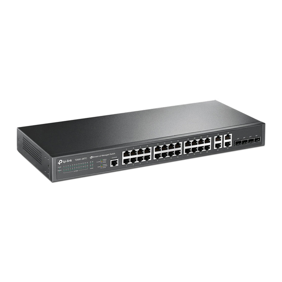
- Page 1 Business Networking Solution Installation Guide L2 Managed Switch T2500-28TC (TL-SL5428E) Downloaded from ManualsNet.com search engine...
- Page 2 No part of the specifications may be reproduced in any form or by any means or used to make any derivative such as translation, transformation, or adaptation without permission from TP-LINK TECHNOLOGIES CO., LTD. Copyright © 2016 TP-LINK TECHNOLOGIES CO., LTD. All rights reserved.
- Page 3 The User Guide and CLI Reference Guide of the product are provided on the resource To obtain the latest product information, please visit the Official Website: http://www.tp-link.com About this Installation Guide This Installation Guide describes the hardware characteristics, installation methods and the points that should be attended to during installation.
- Page 4 Audience This Installation Guide is for: Network Engineer Network Administrator Conventions This guide uses the specific formats to highlight special messages. The following table lists the notice icons that are used throughout this guide. Remind to be careful. A caution indicates a potential which may result in device damage.
-
Page 5: Table Of Contents
Contents Chapter 1 Introduction ———————————— 01 Product Overview .........01 Appearance ..........01 Chapter 2 Installation ————————————— 04 Package Contents .........04 Safety Precautions ........04 Installation Tools ..........06 Product Installation ........06 Chapter 3 Lightning Protection ———————— 08 Cabling Reasonably ........08 Connect to Ground ........10 Equipotential Bonding ........11 Use Lightning Arrester ........12 Chapter 4 Connection —————————————... -
Page 6: Chapter 1 Introduction
L2 Managed Switch Chapter 1 Introduction 1.1 Product Overview TP-LINK JetStream L2 Managed Switch, designed for workgroups and departments, provides wire-speed performance and abundant layer 2 management features. It provides a variety of service features and multiple powerful functions with high security. - Page 7 L2 Managed Switch Note: The port 25–28 of the switch are “Combo” ports. A “Combo” port consists of a RJ45 port and an SFP port, and the two ports share the same LED. Port Feature 10/100Mbps 10/100/1000Mbps Model Console Port SFP Port RJ45 Port RJ45 Port...
- Page 8 L2 Managed Switch Power Socket Connect the female connector of the power cord here, and the male connector to the AC power outlet. Please make sure the voltage of the power supply meets the requirement of the input voltage (100-240V~ 50/60Hz). Caution: Please use the provided power cord.
-
Page 9: Chapter 2 Installation
L2 Managed Switch Chapter 2 Installation 2.1 Package Contents Make sure that the package contains the following items. If any of the listed items is damaged or missing, please contact your distributor. One Switch One Power Cord and one This Installation Guide Console Cable One Resource CD Two mounting brackets and... - Page 10 L2 Managed Switch Please keep a proper temperature and humidity in the equipment room. Too high/low humidity may lead to bad insulation, electricity leakage, mechanical property changes and corrosions. Too high temperature may accelerate aging of the insulation materials and can thus significantly shorten the service life of the device. For normal temperature and humidity of the device, please check the following table.
-
Page 11: Installation Tools
L2 Managed Switch instant current is strong enough to damage electronic devices, more effective lightning protection measures should be taken. Ensure the rack and device are well earthed. ■ Make sure the power socket has a good contact with the ground. ■... - Page 12 L2 Managed Switch 3. Turnover the device and attach the supplied rubber feet to the recessed areas on the bottom at each corner of the device. Feet Bottom of the Device Notch Figure 2-1 Desktop Installation Rack Installation ■ To install the device in an EIA standard-sized, 19-inch rack, follow the instructions described below: 1.
-
Page 13: Chapter 3 Lightning Protection
L2 Managed Switch Chapter 3 Lightning Protection 3.1 Cabling Reasonably In the actual network environment, you may need cable outdoors and indoors, and the requirements for cabling outdoors and indoors are different. A reasonable cabling system can decrease the damage of induced lightning to devices. Note: It’s not recommended to use Ethernet cables outdoors. - Page 14 L2 Managed Switch Requirements for the distance between Ethernet cable and other pipelines are shown ■ in the table. Ethernet Cable Other Pipelines Min Parallel Net Length Min Parallel-overlapping Net Height L (mm) H (mm) Down-conductor 1000 Service pipe Compressed air pipe Thermal pipe (not wrapped) 500 Thermal pipe (wrapped) Gas pipe...
-
Page 15: Connect To Ground
L2 Managed Switch 3.2 Connect to Ground Connecting the device to ground is to quickly release the lightning over-voltage and over-current of the device, which is also a necessary measure to protect the body from electric shock. In different environments, the device may be grounded differently. The following will instruct you to connect the device to the ground in two ways, connecting to the grounding bar or connecting to the ground via the power cord. -
Page 16: Equipotential Bonding
L2 Managed Switch Note: The figure is to illustrate the application and principle. The power cord you get from ■ the package and the socket in your situation will comply with the regulation in your country, so they may differ from the figure above. If you intend to connect the device to the ground via the PE (Protecting Earth) cable ■... -
Page 17: Use Lightning Arrester
L2 Managed Switch 3.4 Use Lightning Arrester Power lightning arrester and signal lightning arrester are used for lighting protection. Power lightning arrester is used for limiting the voltage surge due to a lightning. If an outdoor AC power cord should be directly connected to the device, please use a power lightning arrester. -
Page 18: Chapter 4 Connection
L2 Managed Switch Chapter 4 Connection 4.1 Ethernet Port Connect the Ethernet ports of the switch to the network devices by RJ45 cable as the following figure shows. RJ45 Port RJ45 Cable Figure 4-1 Connecting the RJ45 Port 4.2 SFP Port Connect the SFP port to an SFP module. -
Page 19: Verify Installation
L2 Managed Switch Figure 4-3 Connecting the Console Port You can also manage the device through the console port, for details please refer to the CLI Reference Guide on the resource CD. Note: The console port is the first port on the left of the front panel. ■... -
Page 20: Initialization
L2 Managed Switch Note: The figure is to illustrate the application and principle. The power cord you get from the package and the socket in your situation will comply with the regulation in your country, so they may differ from the figure above. 4.6 Initialization After the device is powered on, it begins the Power-On Self-Test. -
Page 21: Chapter 5 Configuration
L2 Managed Switch Chapter 5 Configuration 5.1 Configure the Switch via GUI Note: To log on to the GUI of the switch, the IP address of your PC should be set in the same subnet addresses of the switch. The IP address is 192.168.0.x ("x" is any number from 2 to 254), Subnet Mask is 255.255.255.0. -
Page 22: Configure The Switch Using Cli
L2 Managed Switch 5.2 Configure the Switch Using CLI You can log on to the switch and access the CLI by the following two methods: Log on to the switch by the console port on the switch. ■ Log on to the switch remotely by a Telnet or SSH connection through an Ethernet ■... - Page 23 L2 Managed Switch 4. Select the port to connect in Figure 5-6, and click OK. Figure 5-6 Select the port to connect 5. Configure the port selected in the step above as the following Figure 5-7 shows. Configure Bits per second as 38400, Data bits as 8, Parity as None, Stop bits as 1, Flow control as None, and then click OK.
- Page 24 L2 Managed Switch 6. The DOS prompt ”T2500-28TC>” will appear after pressing the Enter button as shown in Figure 5-8. It indicates that you can use the CLI now. T2500-28TC Figure 5-8 Log in the Switch Logon by Telnet ■ To log on to the switch by a Telnet connection, please take the following steps: 1.
- Page 25 L2 Managed Switch 4. Type in cmd in the prompt Run window as Figure 5-10 and click OK. Figure 5-10 Run Window 5. Type in telnet 192.168.0.1 in the command prompt shown as Figure 5-11, and press the Enter button. Figure 5-11 Connecting to the Switch 6.
-
Page 26: Appendix A Troubleshooting
L2 Managed Switch Appendix A Troubleshooting What could I do if I forgot the username and password of the switch? 1. Connect the console port of the PC to the console port of the switch and open hyper terminal. 2. Power off and restart the switch. When you are prompted that “Press CTRL-B to enter the bootUtil”... -
Page 27: Appendix B Hardware Specifications
Operating Temperature 0℃~40℃ Storage Temperature -40℃~70℃ Operating Humidity 10%~90%RH Non-condensing Storage Humidity 5%~90%RH Non-condensing For more help, please go to: http://www.tp-link.com/en/support/faq ■ To download the latest Firmware, Driver, Utility and User Guide, go to: ■ http://www.tp-link.com/en/support/download Hardware Specifications Downloaded from ManualsNet.com... - Page 28 Website: http://www.tp-link.com Tel: +86 755 26504400 E-mail: support@tp-link.com 7106506261 REV1.1.0 Downloaded from ManualsNet.com search engine...