Table of Contents

Related Manuals for ABB SafeRing XT


Summary of Contents for ABB SafeRing XT
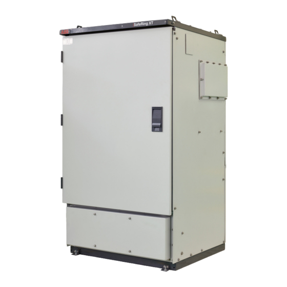
- Page 1 — M A N U A L SafeRing XT/SafePlus XT Installation and operating instructions • Compact and Smarter • No live parts exposed • High reliability and safety • Safe and easy for operators in both maintenance and operating conditions...
- Page 2 — SafeRing XT/SafePlus XT is a ring main unit for the secondary distribution network. SafeRing XT/SafePlus XT can be supplied in a number of different configurations suitable for most switching applications in 12kV distribution networks. Digital solutions like smart automation, control and monitoring &...
-
Page 3: Table Of Contents
3.2.1 Intent 3.2.2. Codes and standards 3.2.3. Storage condition 4. Technical data Electrical data SafeRing XT/SafePlus XT 5. Installation 15-17 Standard 3-Way Ring Main Unit 3 way Ring Main Unit + 3 way Ring Main Unit Coupling Standard 3-Way Ring Main Unit + Metering Module 6. - Page 4 SAFERING XT/SAFEPLUS XT — Table of contents 8. Cable compartment 21-28 Standard Arc proof cable compartment 8.1.1. To Remove cable cover 8.1.2. To Re-fix of cable cover 8.1.3. To Defeat Interlock after Opening Door: Cable connection Cable Clamping arrangements: Cable Earthing arrangements:...
- Page 5 General warnings and cautions 20.2 Maintenance intervals 20.3 Inspection general aspects 20.4 Servicing instructions 20.5 Repairs 20.6 Tool list SafeRing XT/SafePlus XT 21. Environmental certification 21.1 Life expectancy of product 21.2 Recycling capability 21.3 End-of-life ANNEX Sample work instruction 51-52...
-
Page 6: Safety
It is recommended that ABB service personnel to be called to perform the servicing and repair work. Disconnect all sources and secure against reconnection... - Page 7 I N S TA L L AT I O N A N D O P E R AT I N G I N S T R U C T I O N S STEP 1 - Prepare for the work Do an on-site Risk Assessment or Safe Job Analysis (SJA): •...
-
Page 8: Required Certifications
Ensure all parties are integrated with the at your own risk and that ABB shall not be liable for any Lockout/Tagout. damage or loss of any kind, arising by law or otherwise, •... -
Page 9: General Description
The units are delivered from the factory ready for for SafeRing XT/SafePlus XT. installation. SafeRing XT/SafePlus XT can be supplied as a 1, 2, 3, 4 or 5 -way unit in standard configurations with additional equipment according to customer specifications. -
Page 10: Outer Assembly
SAFERING XT/SAFEPLUS XT 2.1 Outer assembly — — Figure 2.2 Figure 2.3 Front door open condition Front door Closed condition Lifting angle/Lugs 18. Protection relay Low Voltage compartment 19. Disconnector operation selector knob Feeder description plate 20. VCB/V Module Mimic Side Extension covers 21. -
Page 11: Outer Assembly Standard Metering Module
I N S TA L L AT I O N A N D O P E R AT I N G I N S T R U C T I O N S 2.2 Outer assembly Standard Metering Module. 1. Lightning arrester jumpers 2. -
Page 12: Transport And Handling
The units are delivered from the factory ready for installation. 3.1 Packing The SafeRing XT/SafePlus XT is normally delivered packed from the factory. For longer transportation distances, protective measures such as wooden corners, plastic film etc., are used. This should be removed, when the RMU is at site and before installation. -
Page 13: Storage
3.2 Storage dust etc. Also recommended to avoid the storage SafeRing XT/SafePlus XT must be stored under cover in a dry directly under the rain for the period not more than and well-ventilated area until it is installed and put into two months. -
Page 14: Technical Data
SAFERING XT/SAFEPLUS XT — 4. Technical data 4.1 Electrical data SafeRing XT/SafePlus XT Technical Data C-Module V-Module SafeRing XT/SafePlus XT Switch- Earthing Switch Vacuum Disconnector- Disconnector circuit-breaker earthing switch Rated voltage Power frequency kVrms withstand voltage Across Disconnector/ kVrms Switch-Disconnector... -
Page 15: Installation
I N S TA L L AT I O N A N D O P E R AT I N G I N S T R U C T I O N S — 5. Installation 5.1 Standard 3-Way Ring Main Unit —... -
Page 16: Standard 3-Way Ring Main Unit + Metering Module
SAFERING XT/SAFEPLUS XT 5.2 3 way Ring Main Unit + 3 way Ring Main Unit Coupling Ring Main Unit 1 Ring Main Unit 2 Ring Main Unit 1 Ring Main Unit 2 (Refer Chapter 2.1) (Refer Chapter 2.1) (Refer table from Chapter 5.1) (Refer table from Chapter 5.1) - Page 17 I N S TA L L AT I O N A N D O P E R AT I N G I N S T R U C T I O N S Flatness of concrete plinth area should be within ±2 mm. This area only considers switchgear foundation.
-
Page 18: Dimensions
— 6. Dimensions 6.1 Weight table NOTE! ABB wishes to highlight that values of dimensions and SafeRing XT/SafePlus XT the weights are weights provided herein are preliminary and may change after final design preparation, based on final scope of Module RMU weight In kg supply and installation details of the switchgear. -
Page 19: Internal Arc Classification (Iac)
I N S TA L L AT I O N A N D O P E R AT I N G I N S T R U C T I O N S — 7. Internal arc classification (IAC) During development of all ABB products, focus is on All test specimens passed the following test criteria personnel safety. The SafeRing XT/SafePlus XT portfolio was... -
Page 20: Iac Aflr
SAFERING XT/SAFEPLUS XT SafeRing XT/SafePlus XT is available for a wide range of 100 mm recommended for non-accessible Rear/ installations and applications in order to secure the highest Lateral side. safety for operators. 700mm Minimum height of the cable trench... -
Page 21: Cable Compartment
I N S TA L L AT I O N A N D O P E R AT I N G I N S T R U C T I O N S — 8. Cable compartment 8.1 Standard Arc proof cable compartment 2. -
Page 22: To Re-Fix Of Cable Cover
SAFERING XT/SAFEPLUS XT 8.1.2. To Re-fix of cable cover: 3. Lift the door upward ↑ direction, then tilt outward and open door completely. 1. Ensure the Switch-Disconnector/Disconnector of respective module is in Earth position. 2. To Re-fix the cable door, hold door in tilted position and engage the teeth of door with slots on the cable compartment and then Push inside 3. -
Page 23: To Defeat Interlock After Opening Door
I N S TA L L AT I O N A N D O P E R AT I N G I N S T R U C T I O N S 8.1.3. To Defeat Interlock after Opening Door: 1. - Page 24 SAFERING XT/SAFEPLUS XT To remove Defeat Interlock follow the arrow in reverse Before using Defeat Interlock. direction. 1. Ensure the Switch-Disconnector/Disconnector of Ensure the Switch-Disconnector/Disconnector of respective respective module is in Earth position module is in Earth position. 2. Ensure cable door is opened condition iii) Dis-engage the defeat interlock from flange 3.
-
Page 25: Cable Connection
I N S TA L L AT I O N A N D O P E R AT I N G I N S T R U C T I O N S 8.2 Cable connection It is recommended to have cable terminations kits and boots/elbows from the same manufacturer so as to avoid compatibility Issues. - Page 26 SAFERING XT/SAFEPLUS XT SafeRing XT/SafePlus XT can be supplied with the bushings as shown below : DANGER ! Following pictures shows the tightening torque and fasteners to be used for the bushing terminations. Cable size of maximum 400 sq. mm can be used.
- Page 27 6. Outer conductive layer 7. Adapter 8. Earth connection 9. Designed for polymeric insulated cables 10. Capacitive test point (optional) The following manufacturers of cable terminations are recommended: SafeRing XT screened termination kit suitability Single Cable Double cable 1 Cable+Surge arrester Make Model...
-
Page 28: Cable Clamping Arrangements
SAFERING XT/SAFEPLUS XT 8.3 Cable Clamping arrangements: 8.5 Removal of Bottom cover During Cable termination, remove the bottom cover of the RMU for easy routing & pulling of cables. Ensure once termination is completed bottom cover is refixed with proper hardware as per table WASH-N_ISO7089_8x16x1,6-PA6/NC WASH-SP_DIN6796_8.4/18-X39CRM017-1/PL... -
Page 29: Extension Of Switchgear
I N S TA L L AT I O N A N D O P E R AT I N G I N S T R U C T I O N S — 9. Extension of switchgear 9.1 External busbar SafePlus XT can be equipped with a side extension. -
Page 30: Current And Voltage Transformers
SAFERING XT/SAFEPLUS XT — 10. Current transformers SafeRing XT/SafePlus XT can be equipped with current transformers. — Figure 10.3 CT Fixing Step 02 — Figure 10.1 CT Mounting details NOTE For the easy termination of cables, adjustable arrangements are given for current transformers. - Page 31 I N S TA L L AT I O N A N D O P E R AT I N G I N S T R U C T I O N S • Follow step 4 to 6 to fix additional set of CT's per phase 4.
-
Page 32: Motor Operation
SAFERING XT/SAFEPLUS XT — 11. Motor operation Switches, vacuum circuit-breakers, and earthing switches For upgradation/retrofitting of motorized operation refer are operated by mechanisms located behind the front separate document number 2REA064412 mimic. The mechanisms for all the switches and breakers are operated manually with the operating lever (standard), or are fitted with motor operation (additional equipment). -
Page 33: Protection
A protection relay is installed in each vacuum circuit-breaker Relays with auxiliary voltage module. The cables from the protection relay to the current SafeRing XT/SafePlus XT with vacuum circuit-breakers are transformers are installed from the factory and are delivered with self-powered relays terminated in the cable compartment to the three current transformers. -
Page 34: Pressure Indicator
SafeRing / SafePlus contain SF6 gas with a nominal pressure of 1,3 bar absolute at 20 WARNING! SafeRing XT/SafePlus XT are «sealed for life» and fitted with Replenishment of SF6 gas in SafeRing XT/ SafePlus XT a temperature-compensated pressure indicator. -
Page 35: Altitude
1000 meters. For installation above 1000 meters, 2. Screw the adapter to the valve. The tightening torque is please contact ABB for instructions. max 45 Nm. 13.2.1 Adjustment of gas pressure in higher altitudes 3. Before connecting the hose from the gas bottle to the... -
Page 36: Operation Of The Switchgear
The manufacturer / supplier must be consulted in advance DANGER! if especially difficult operating conditions are involved. When SafeRing XT/SafePlus XT is installed more than 1000 Do not walk on the top of switchgear units!. meters above sea level, the atmospheric pressure will be lower and the overpressure inside the tank will have to be reduced. -
Page 37: Putting Into Service
I N S TA L L AT I O N A N D O P E R AT I N G I N S T R U C T I O N S 14.3 Putting into service Other checkpoints • Depending on the allocation of responsibilities, it may also be necessary to check the following equipment in the Preparatory work... -
Page 38: Operation
SAFERING XT/SAFEPLUS XT — 15. Operation All switches can be operated with the included operating handle. Internal mechanical interlocking between the Switch disconnector / Disconnector and the associated earthing switches prevents incorrect operation. The operation of the switch Disconnector, Disconnector/Circuit-breaker and Earthing switches can be further interlocked by means of a padlock. -
Page 39: Operation Of C Module Switch Disconnector With Push-Buttons
I N S TA L L AT I O N A N D O P E R AT I N G I N S T R U C T I O N S 15.2 Operation of C module switch Disconnector with push-buttons If an additional Motor is installed in the C module Switch disconnector, push-buttons are also mounted on the system. - Page 40 SAFERING XT/SAFEPLUS XT • Vacuum circuit-breaker Operation : 1. VCB is in Open condition and spring is discharged. 2. Charge the spring by means of the charging lever. 3. The spring is fully charged when the indicator turns to charged spring (yellow symbol), about 10 operations needed to fully charge the spring.
-
Page 41: Operation Of The Disconnector In The V-Module
I N S TA L L AT I O N A N D O P E R AT I N G I N S T R U C T I O N S 15.4 Operation of the Disconnector in the •... -
Page 42: Metering Module
SAFERING XT/SAFEPLUS XT — 16. Metering module 16.1 To get access to metering module DANGER ! Make sure there is no voltage in the busbars and cable 1. Unlock the front lock and then open the main door. terminals and that the risk of reconnection is eliminated 2. -
Page 43: Capacitive Voltage Indicators
I N S TA L L AT I O N A N D O P E R AT I N G I N S T R U C T I O N S — 17. Capacitive voltage indicators 17.1 Voltage indicator VPIS VPIS indicators are used to indicate the presence of service medium voltage WARNING! -
Page 44: Additional Equipment
A shunt trip coil and Close coil (AC or DC) can be fitted on V Module Circuit breaker. 18.2 Remote control and monitoring unit SafeRing XT/SafePlus XT can be equipped with an integrated remote control and monitoring unit This unit is pre-engineered and can be delivered and installed as a retrofit solution or complete from factory. -
Page 45: Cable Testing
This is typically done by cable can be tested at the same time. This is feasible, but opening the disconnectors of SafeRing XT/SafePlus XT remember the following limitations: DC and VLF voltages switchgears connected to the cable. The free end of the... -
Page 46: Service And Maintenance
Mild alkaline cleaning agent. Do not use trichloroethane, carbon carbotetrachloride or any kind of alcohol, etc. for Other services may be required, as when max number cleaning of operations is reached, please contact ABB to order • Clean water inspection. -
Page 47: Inspection General Aspects
Should partial discharges occur as a result of condensation, application of a thin silicone film over the surface concerned is often effective as a temporary remedy. It is advisable to ask the ABB after- sales service department for advice regarding permanent solutions to this uncommon type of problem. -
Page 48: Tool List Safering Xt/Safeplus Xt
SAFERING XT/SAFEPLUS XT 20.6 Tool list SafeRing XT/SafePlus XT Required Tools Adjustable wrench 10“ NOTE Side cutting plier - ergo Strippling plier The following list of tools does NOT cover tools needed Universal plier for HV or LV cable work/handling or testing. - Page 49 I N S TA L L AT I O N A N D O P E R AT I N G I N S T R U C T I O N S Required Required Tools Tools Extra tools Screwdriver - Flat 1,2 x 8 x150 Screwdriver - Flat 1,2 x 6,5 x100 Head lamp - LED Screwdriver - Flat 0,5 x 3 x75...
-
Page 50: Environmental Certification
6.5.2.a: «Low decomposition»: «No special action is required; non- recoverable parts can be disposed of normally according to local regulations.» ABB India Ltd, Electrification Products division in Nashik is equipped to reclaim SF gas from discarded switchgears. -
Page 51: Annex Sample Work Instruction
I N S TA L L AT I O N A N D O P E R AT I N G I N S T R U C T I O N S — ANNEX Sample work instruction Handling of uncontaminated SF Works department: Work Instruction Issue date:... - Page 52 SAFERING XT/SAFEPLUS XT — ANNEX Sample work instruction Handling of contaminated SF Works department: Work Instruction Issue date: Working area: Work place: Activity: Handling of contaminated SF Responsible Person HAZARDOUS MATERIAL DESIGNATION Sulphur hexafluoride (SF ) with decomposition products (contaminated SF...
- Page 53 abb.com...
- Page 54 abb.com...
- Page 56 Toll Free Number: 1800 420 0707 Mail Id: ppmvsupport@in.abb.com — ABB India Ltd. ELDS Plot No.79, Street No. 17 MIDC, Satpur, Nashik - 422 007 Maharastra - India www.abb.com/medium-voltage/switchgear © Copyright 2022 ABB. All rights reserved. Specifications subject to change without notice.