Advertisement
Quick Links
Owner's Manual & Safety Instructions
Save This Manual
operating, inspection, maintenance and cleaning procedures. Write the product's serial number in the
back of the manual near the assembly diagram (or month and year of purchase if product has no number).
Keep this manual and the receipt in a safe and dry place for future reference.
Email our technical support at: productsupport@harborfreight.com
When unpacking, make sure that the product is intact
and undamaged. If any parts are missing or broken,
please call 1-888-866-5797 as soon as possible.
©
Copyright
2021 by Harbor Freight Tools
No portion of this manual or any artwork contained herein may be reproduced in
any shape or form without the express written consent of Harbor Freight Tools.
Diagrams within this manual may not be drawn proportionally. Due to continuing
improvements, actual product may differ slightly from the product described herein.
Tools required for assembly and service may not be included.
Keep this manual for the safety warnings and precautions, assembly,
Visit our website at: http://www.harborfreight.com
®
. All rights reserved.
Read this material before using this product.
Failure to do so can result in serious injury.
SAVE THIS MANUAL.
21k
58005
Advertisement

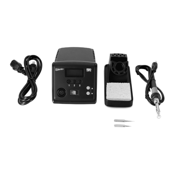
Summary of Contents for Harbor Freight Tools Schneider 58005
- Page 1 No portion of this manual or any artwork contained herein may be reproduced in Failure to do so can result in serious injury. any shape or form without the express written consent of Harbor Freight Tools. Diagrams within this manual may not be drawn proportionally. Due to continuing SAVE THIS MANUAL.
-
Page 2: Table Of Contents
Table of Contents Safety ................2 Maintenance .............10 Specifications ............6 Parts List and Diagram ..........11 Setup .................6 Warranty ..............12 Operation ..............7 WARNING SYMBOLS AND DEFINITIONS This is the safety alert symbol. It is used to alert you to potential personal injury hazards. Obey all safety messages that follow this symbol to avoid possible injury or death. -
Page 3: Safety
Electrical safety 1. Power tool plugs must match the outlet. 4. Do not abuse the cord. Never use the cord Never modify the plug in any way. for carrying, pulling or unplugging the Do not use any adapter plugs with grounded power tool. - Page 4 If unreadable or missing, contact such as cancer of the larynx and lung Harbor Freight Tools for a replacement. cancer. Also, some diseases that may be 9. Do not leave the tool unattended when linked to exposure to soldering fumes are: it is plugged into an electrical outlet.
- Page 5 Grounded Tools: Tools with Three Prong Plugs 2. The grounding prong in the plug is connected through the green wire inside the cord to the grounding system in the tool. The green wire in the cord must be the only wire connected to the tool’s grounding system and must never be attached to an electrically “live”...
-
Page 6: Specifications
Symbology Read the manual before Volts set-up and/or use. WARNING marking Alternating Current concerning Risk of Fire. Do not cover ventilation ducts. Amperes Keep flammable objects away. WARNING marking concerning WARNING marking concerning Risk Risk of Electric Shock. of Eye Injury. Wear ANSI-approved Properly connect power cord safety goggles with side shields. -
Page 7: Operation
Operating Instructions Read the ENTIRE IMPORTANT SAFETY INFORMATION section at the beginning of this manual including all text under subheadings therein before set up or use of this product. Note: For additional information regarding the parts listed in the following pages, refer to Parts List and Diagram on page 11. Workpiece and Work Area Set Up 1. - Page 8 General Operating Instructions TO PREVENT SERIOUS INJURY: Wear ANSI-approved safety goggles with side shields. 1. Plug Power Cord into grounded 120VAC outlet. 4. Clean and tin Tip, apply a sufficient amount of rosin-core solder to melt over the entire 2. Turn Power Switch on. Soldering Tip.
- Page 9 Settings 4. Automatic Standby To enter Settings mode, press and hold for three seconds. a. Enter Settings mode, then press 1. Calibration b. Press 1, Screen will display Stb and current status will be shown. a. Press 1, Screen will display CAL and last calibration value will be shown.
-
Page 10: Maintenance
Maintenance and Servicing Procedures not specifically explained in this manual must be performed only by a qualified technician. TO PREVENT SERIOUS INJURY FROM ACCIDENTAL OPERATION: Make sure that the Trigger is in the off-position, unplug the tool from its electrical outlet, and allow it to cool completely before performing any procedure in this section. -
Page 11: Parts List And Diagram
Parts List and Diagram Part Description Part Description Power Cord Preset Temperature Button Set Fuse (T2.0A) Manual Temperature Button Set Male Socket Power Switch Soldering Iron Stand Soldering Iron Outlet Sponge Soldering Iron Cable Top Housing Soldering Iron handle end sleeve PCBA Screw Soldering Iron handle sleeve PCBA... -
Page 12: Warranty
Limited 90 Day Warranty Harbor Freight Tools Co. makes every effort to assure that its products meet high quality and durability standards, and warrants to the original purchaser that this product is free from defects in materials and workmanship for the period of 90 days from the date of purchase. This warranty does not apply to damage due directly or indirectly, to misuse, abuse, negligence or accidents, repairs or alterations outside our facilities, criminal activity, improper installation, normal wear and tear, or to lack of maintenance.