
Related Manuals for CAME V700E


Summary of Contents for CAME V700E
- Page 1 AUTOMAZIONE PER PORTE BASCULANTI E SEZIONALI FA 006 71 M 0 4 MANUALE D’INSTALLAZIONE Italiano V700E English Français Русский...
-
Page 2: Leggere Attentamente
SENSORIALI O MENTALI ESPRESSAMENTE STUDIATO GNI ALTRO USO È DA CONSIDERARSI PERICOLOSO SIANO RIDOTTE OPPURE CON MANCANZA DI ESPERIENZA O DI CONOSCENZA CAME S. ’ NON È RESPONSABILE PER EVENTUALI DANNI CAUSATI DA USI MENO CHE ESSE ABBIANO POTUTO BENEFICIARE ATTRAVERSO L INTERMEDIAZIONE •... -
Page 3: Legenda Simboli
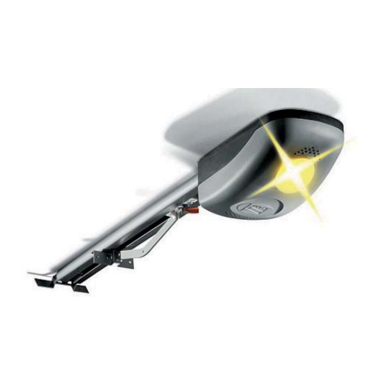
Automazione Questo prodotto è progettato e costruito dalla CAME CANCELLI AUTOMATICI S.p.A. in conformità alle vigenti norme di sicurezza. L’automazione è composta principalmente da un gruppo motore, una barra di scorrimento - con sistema di trazione a cinghia o a catena - e un braccio di trasmissione. -
Page 4: Dati Tecnici
2) 001V0670 - Scheda di collegamento batterie d’emergenza, con supporto per 2 batterie (12V-1,2Ah escluse) Importante! Controllare che le apparecchiature di comando, di sicurezza e gli accessori siano originali CAME; ciò garantisce una facile installazione e manutenzione dell’impianto. Dati tecnici MOTORIDUTTORE V700E Alimentazione quadro: 230V A.C. -
Page 5: Installazione
Misure di ingombro 400 mm 3020 mm min. ÷ 4020 mm max. Installazione L’installazione deve essere effettuata da personale qualificato ed esperto e nel pieno rispetto delle normative vigenti. Verifiche preliminari Prima di procedere all’installazione dell’automatismo è necessario: • Verificare che l’installazione dell’automazione non generi situazioni di pericolo; •... -
Page 6: Impianto Tipo
Impianto tipo 1) Gruppo motoriduttore 2) Quadro comando incorporato con ricevitore radio 3) Barra di scorrimento 4) Dispositivo di sblocco 5) Braccio di trasmissione standard 6) Selettore a chiave 7) Lampeggiatore di movimento 8) Antenna di ricezione 9) Fotocellule di sicurezza 10) Pulsantiera da interno 11) Bordo sensibile Esempi di applicazione... - Page 7 1) Fissare la staff a al dispositivo di tensionamento della guida di trasmissione con le viti e i dadi in dotazione. M6 x 20 2) Posizionare la guida di scorrimento nel seguente modo: - per porte sezionali sopra l’ingombro della staff a del palo-molla. N.B.: se la distanza tra il palo-molla e la parte superiore della porta è...
- Page 8 Fissaggio della guida di scorrimento 1) Fissare la barra di scorrimento al centro del vano porta con viti adeguate. Sollevare la barra e disporla orizzontalmente per rilevare la distanza dal soffi tto allo scopo di scegliere il tipo di fi ssaggio. 2) Se gli angolari non sono suffi cienti, tagliare i tiranti nella misura necessaria e fi...
- Page 9 Fissaggio del braccio di trasmissione alla barra di scorrimento 1) Fissare braccio di trasmissione al traverso superiore della porta perpendicolarmente alla barra di scorrimento. Utilizzare i rivetti in dotazione o altre viti adeguate. 2) Sbloccare la slitta di trascinamento girando la levetta in senso orario. Spostare la slitta verso la porta e agganciarla al braccio di trasmissione con il bullone in dotazione UNI 5739 M6 x 20...
- Page 10 Fissaggio del motoriduttore alla barra di trasmissione 1) Togliere il coperchio del contenitore del gruppo motore. UNI 6954 ø 3.9 x 13 2) Fissare il gruppo motore al supporto di sostegno della barra con le tre viti in dotazione. N.B.: se necessario, il gruppo può essere fi ssato nelle altre tre posizioni ortogonali, come da disegno. UNI 6955 ø...
-
Page 11: Descrizione Generale
Scheda elettronica di comando Descrizione generale La scheda di comando va alimentata a 230V sui morsetti L-N, frequenza 50/60Hz. I dispositivi di comando e gli accessori sono a 24V. Inoltre gli accessori non devono superare complessivamente i 40W. La scheda controlla una lampada di servizio per illuminare la zona di manovra; a ogni apertura rimane accesa per 2 minuti e 30 secondi. -
Page 12: Componenti Principali
Componenti principali 1) Fusibile di linea 1.6A 2) Spazio per batterie d’emergenza 3) Motoriduttore 4) Trasformatore 5) Morsettiera collegamento trasformatore 6) Fusibile motore 8A 7) Morsettiera collegamento motoriduttore 8) Morsettiera collegamento encoder 9) Led segnalazione radio e programmazione encoder 10) Pulsante di memorizzazione codice radio 11) Trimmer SLOW.SENS: regolazione della sensibilità... - Page 13 Motoriduttore, encoder e trasformatore (solo per eventuali manutenzioni) Motoriduttore Trasformatore 24V d.c. ed encoder Dispositivi di comando e sicurezza Se viene collegato un dispositivo, togliere il ponticello Pulsante di stop (contatto N.C.) - Arresta il movimento, escludendo la chiusura automatica. Per il ripristino dell’automatismo, premere un pulsante di comando o un tasto del radiocomando.
- Page 14 Dispositivi di segnalazione Lampeggiatore di movimento (portata contatto: 24V - 25W max.) - Lampeggia in fase di apertura e chiusura Selezione funzioni 1 ON - Attiva la procedura di regolazione dei fi necorsa di apertura e di chiusura e la procedura di programmazione per la partenza rallentata in apertura 2 ON - Attiva la procedura di regolazione per l’apertura parziale e la procedura di programmazione per il rallentamento a fi...
-
Page 15: Operazioni Preliminari
Programmazione Programmazione dei finecorsa di chiusura e apertura IMPORTANTE: prima di procedere con la programmazione dei fi necorsa, leggere attentamente le istruzioni. Seguire nell’ordine le successive istruzioni altrimenti la programmazione non avrà esito positivo. 1 - Operazioni preliminari - Sbloccare l’automazione e posizionare la porta nel punto di massima apertura. - A porta completamente aperta, fi... - Page 16 ...quindi premere il tasto ENC/RADIO fino a quando il led di segnalazione rimane acceso per alcuni secondi e poi riprende a lampeggiare (l’operazione di programmazione si è conclusa positivamente). OP.SENS. OP / CL OPEN ENC/RADIO OP.SENS. OP / CL OPEN ENC/RADIO SLOW.SENS A.C.T.
- Page 17 Programmazione per l’apertura parziale A portone completamente chiuso, posizionare il dip 2 in ON (il led di segnalazione programmazione lampeggia). Premere e tenere premuto il tasto OPEN fi no a quando il portone raggiunge il punto di apertura desiderata..premere poi il tasto ENC/RADIO (se il led di segnalazione rimane acceso l’operazione di programmazione si è conclusa positivamente).
- Page 18 Premere il tasto OP/CL fi no a quando il portone raggiunge il punto di fi ne rallentamento desiderato; premere poi il tasto ENC/RADIO fi no a quando il led di segnalazione rimane acceso (l’operazione di programmazione si è conclusa positivamente). Riportare il dip 1 in OFF.
- Page 19 Attivazione del radiocomando 1 - Antenna Collegare l’antenna con il cavo RG58 agli appositi morsetti sulla scheda. 2 - Scheda di radiofrequenza Innestare la scheda di radiofrequenza sulla scheda elettronica DOPO AVER TOLTO LA TENSIONE (o scollegato le batterie). N.B.: La scheda elettronica riconosce la scheda di radiofrequenza solo quando viene alimentata. OPEN ENC/RADIO OP.SENS.
- Page 20 4 - Memorizzazione e cancellazione utenti radio Attivazione comando sequenziale (2-7) Tenere premuto il tasto ENC/RADIO sulla scheda elettronica. Il led lampeggia. Premere il tasto (T1) del trasmettitore da memorizzare. Il led rimarrà acceso a segnalare l’avvenuta memorizzazione. ENC/RADIO LED acceso Scheda radio AF LED intermittente Attivazione comando di apertura parziale (2-3P)
-
Page 21: Manutenzione Periodica
Manutenzione Manutenzione periodica Gli interventi periodici a cura dell’utente sono la pulizia dei vetrini delle fotocellule e il controllo del corretto funzionamento dei dispositivi di sicurezza e che non ci siano impedimenti per il funzionamento dell’automatismo. Si consiglia inoltre un controllo periodico sulla lubrificazione e sull’allentamento delle viti di fissaggio dell’automatismo. - Per controllare l’efficenza dei dispositivi di sicurezza, passare con un oggetto davanti le fotocellule durante la movimentazione in fase di chiusura, se avviene l’inversione o il blocco della mano- vra, le fotocellule funzionano correttamente. -
Page 22: Manutenzione Straordinaria
Registro manutenzione periodico a cura dell’utente (ogni 6 mesi) Data Annotazioni Firma Manutenzione straordinaria La seguente tabella serve per registrare gli interventi di manutenzione straordinaria, di riparazione e di miglioramento eseguiti da ditte esterne specializzate. N.B. Gli interventi di manutezione straordinaria devono essere effettuati da tecnici specializzati. Registro manutenzione straordinaria Timbro installatore Nome operatore... -
Page 23: Riferimenti Normativi
_______________________________________________________________ Dismissione e smaltimento ☞ CAME S.p.A. implementa all’interno dei propri stabilimenti un Sistema di Gestione Ambientale certificato e conforme alla norma UNI EN ISO 14001 a garanzia del rispetto e della tutela dell’ambiente. Vi chiediamo di continuare l’opera di tutela dell’ambiente, che CAME considera uno dei fondamenti di sviluppo delle proprie strategie operative e di mercato, semplicemente osservando brevi indicazioni in materia di smaltimento: SMALTIMENTO DELL’IMBALLO... - Page 24 Came S.p.A. Came S.p.A. Via Martiri Della Libertà, 15 Via Cornia, 1/b - 1/c 31030 Dosson di Casier Dosson di Casier 33079 Sesto al Reghena Sesto al Reghena Treviso Treviso - Italy Pordenone Pordenone - Italy (+39) 0422 4940 (+39) 0434 698111...
- Page 25 AUTOMATION FOR SECTIONAL AND OVERHEAD DOORS FA 00671 - EN INSTALLATION MANUAL V700E English...
-
Page 26: Read Carefully
ALL ANCHORING POINTS INCLUDING WHICH IT WAS EXPLICITLY DESIGNED NY OTHER USE IS DANGEROUS CABLES AND ANY ACCESSIBLE CONNECTIONS EEP ANY HINGES MOVING JOINTS CAME S. • P LIABLE DAMAGE CAUSED AND SLIDE RAILS PROPERLY LUBRICATED ERFORM FUNCTIONAL CHECKS ON •... -
Page 27: Legend Of Symbols
Automation V700E was designed and manufactured by CAME CANCELLI AUTOMATICI S.p.A. and is compliant with the safety regulations in force. The automation is mainly made up of an engine block, a transmission rail - with either a belt or chain transmission system - and a transmission arm. -
Page 28: Technical Specifications
2) 001V0670 - Emergency battery start-up card, houses 2 (12V-1,2Ah not included) batteries ; Important! Check that the safety equipment and accessories are CAME originals; this is a guarantee that also makes the system easy to set up and upkeep. -
Page 29: Installation
Size measurements 400 mm 3020 mm min. ÷ 4020 mm max. Installation The installation must be carried out by export, qualified personnel in total compliance with the norms in effect. Preliminary checks Before proceeding with the installation, it is necessary to: •... - Page 30 Standar installation 1) Gearmotor unit 2) Incorporated control panel with radio transmitter 3) Transmission guide 4) Release device 5) Standard transmission arm 6) Key-switch selector 7) Flashing light movement indicator 8) Tuned antenna 9) Safety photocells 10) Indoor push button control 11) Safety sensitive profi...
- Page 31 1) Fasten the bracket to the tension device on the transmission guide using the supplied bolts and washers. M6 x 20 2) Position the transmission guide in the following manner: - for sectional doors directly above spring-release coiling shaft (between 20 and 30 mm of the shaft’s axis). N.B.: if the distance between the coiling shaft and the top part of the door is between 300 and 600 mm, use the V122 arm (see technical documentation attached);...
- Page 32 Fastening the transmission guide 1) Fasten the transmission guide to the centre of the doorway using the proper screws. Raise the guide until it is horizontal with the ceiling so as to choose the proper type of fastener. 2) If the angle brackets are not suffi cient, cut the tension brackets down to the right length and fasten them to the ceiling. N.B.: to strengthen the bar additional angle or tension brackets may be installed (item code 119RIE024 and 119RIE028) M6 x 14 3) Fasten the transmission guide to the ceiling using the proper bolts.
- Page 33 Fastening the guide arm to the transmission guide 1) Fasten the guide arm to the top of the door frame, perpendicularly to the transmission guide. Use the supplied rivets and other suitable bolts and screws. 2) Release the traction slide by turning the small level clockwise. Move the slide towards the door and hook it onto the guide arm with the supplied bolt.
- Page 34 Fastening the gearmotor to the transmission guide 1) Remove the cover of the motor unit. UNI 6954 ø 3.9 x 13 2) Fasten the motor unit to guide’s support racket using the three screws supplied with the kit. N.B.: if needed, the unit may be fasten in the other three perpendicular positions, as per the drawings. UNI 6955 ø...
-
Page 35: Electronic Control Panel
Electronic control panel General description The control panel is powered by 230V on the L-N terminals, with a 50/60 Hz frequency. The command devices and accessories run on 24V. Moreover, the total accessories cannot run on more than 40W. The panel controls a service light to light up the service area; at each opening it lights up for 2 minutes and 30 seconds. The V0670 card may be connected to operate the automation kit with emergency batteries (see the technical documentation attached). -
Page 36: Main Components
Main components 1) Line fuse 1.6A 2) Emergency batteries’ slot 3) Gearmotor 4) Transformer 5) Transformer connection terminal board 6) Motor fuse 8A 7) Gearmotor connection terminal board 8) Encoder connection terminal board 9) Signal Led for radio-code and encoder programming 10) Radio-code save button 11) SLOW. - Page 37 Gearmotor, encoder and transformer (only for possibile maintenance) Gearmotor 24V Transformer d.c. with encoder Command and safety devices If a device is connected up, remove the small bridge. Stop button (N.C. contact) - Stops movement, excludes the automatic closing functions. To restart the automated kit, press a command button or a remote control button.
-
Page 38: Function Selection
Warning devices Movement Flasher (contact capacity: 24V – 25W max.) Flashes during the opening and closing phases. Function selection 1 ON - Activates the procedure for adjusting the opening and closing endpoints and the procedure for programming the decelerated opening. 2 ON - Activates the procedure for adjusting the partial opening and the procedure for programming the decelerated endpoint closing. -
Page 39: Preliminary Operations
Programming Programming the end-stop in the closing and opening phase IMPORTANT: before performing any programming, read the instructions carefully. Carry out the following instructions in the proper order otherwise the programming will fail. 1 - Preliminary operations - Release the automation and position the door in the fully opened position. - When the door is fully opened, fasten the mechanical stop to the traction slide. - Page 40 ...then press the ENC/RADIO button until the signalling led stays on for some seconds and then resumes blinking (the programming operation is satisfactorily complete). OP.SENS. OP / CL OPEN ENC/RADIO OP.SENS. OP / CL OPEN ENC/RADIO SLOW.SENS A.C.T. CL.SENS. SLOW.SENS A.C.T.
- Page 41 Programming for partial opening With the door is completely closed, set DIP switch 2 to ON (the signalling led fl ashes). Press and keep the OPEN button pressed until the door reaches the desired point of opening..then press the ENC/RADIO button (if the signalling LED stays on the programming procedure is successfully complete). Set DIP switch 2 back to OFF OP.SENS.
- Page 42 Press the OP/CL button until the gate reaches the fi nal point of deceleration you require; then press the ENC/RADIO button until the signalling LED staus on ( the programming procedure is completed succesfully). Set DIP switch 1 back to OFF. Programming for closing deceleration (600 mm from the closing stop minimum, or 50% of the opening/closing arc) With the door completely closed, press and keep pressed the ENC/RADIO button (the signalling programming LED fl...
-
Page 43: Activating The Remote Control
Activating the remote control 1 - Antenna Connect the antenna with the RG58 cable to the apposite terminals on the board. 2 - Radio frequency Connect the radiofrequency card to the electrical board AFTER SHUTTING OFF THE POWER (or disconnecting the batteries). N.B.: The circuit board recognizes the readiofrequency card only when it is running in electrical power. - Page 44 4 - Memorising and deleting radio users Activating the (2-7) sequential command Keep the ENC/RADIO pressed on the circuit board. The led indicator will fl ash. press the transmitter button (T1) to be memorised. The led indicator will stay on to confi rm memorisation. ENC/RADIO Lit LED AF Card...
-
Page 45: Periodic Maintenance
Maintenance Periodic maintenance Periodic maintenance to be carried out by the end-user is as follows: wipe clean the glass surface of the photocells; check that the safety devices work properly; remove any obstructions. We suggest checking the state of lubrication and tightness of the anchoring screws on the operator. - To check the efficiency of the safety devices, move an object in front of the photocells when gate is closing. -
Page 46: Extraordinary Maintenance
Periodic maintenance log to be done by users (every 6 months) Date Notes Signature Extraordinary maintenance The following table is used to log extraordinary maintenance, repair and improvement jobs done by the specialised external firms. N.B. All extraordinary maintenance jobs must be carried out by skilled technicians. Extraordinary maintenance log Installer's stamp Product name... -
Page 47: Demolition And Disposal
☞ CAME S.p.A. implements an EN ISO 14001 certified and compliant Environmental Management System at its plants, to ensure environmental protection. Please continue our efforts to protect the environment, something that CAME considers to be one of the foundations in developing its business and market strategies, simply by observing brief recommendations as regards disposal: DISPOSAL OF PACKAGING Packaging components (cardboard, plastic etc.) can be disposed of together with normal household waste without any difficulty, by simply... - Page 48 Came S.p.A. Came S.p.A. Via Martiri Della Libertà, 15 Via Cornia, 1/b - 1/c 31030 Dosson di Casier Dosson di Casier 33079 Sesto al Reghena Sesto al Reghena Treviso Treviso - Italy Pordenone Pordenone - Italy (+39) 0422 4940 (+39) 0434 698111...
- Page 49 AUTOMATION POUR PORTES SECTIONNELLES ET BASCULANTES FA 006 71 -FR MANUEL POUR L’INSTALLATION V700E Français...
- Page 50 ÉTÉ EXPRESSÉMENT CONÇU OUTE AUTRE UTILISATION EST À CONSIDÉRER COMME À MOINS QU ELLES NE BÉNÉFICIENT PAR LE BIAIS D UNE PERSONNE RESPONSABLE DE CAME S. DANGEREUSE A SOCIÉTÉ DÉCLINE TOUTE RESPONSABILITÉ EN CAS LEUR SÉCURITÉ UNE SURVEILLANCE OU D...
-
Page 51: Légende Des Symboles
Description Automation L’automatisme V700E a été conçu et fabriqué par CAME CANCELLI AUTOMATICI S.p.A. conformément aux normes de sécurité en vigueur. L’automation est composée principalement d’un groupe moteur, d’une barre de coulissement - avec un système de traction à courroie ou à... -
Page 52: Renseignements Techniques
2) 001V0670 - Carte de connexion aux batteries de secours, avec support pour 2 batteries (12V-1,2Ah exclus) Important! Vérifi er si les appareils de commande et de sécurité ainsi que les accessoires sont d’origine CAME; ceci facilite le montage et la maintenance du système. -
Page 53: Contrôles Préliminaires
Dimensions 400 mm 3020 mm min. ÷ 4020 mm max. Installation Le montage doit être effectué par du personnel qualifié et expérimenté dans le respect des normes en vigueur. Contrôles préliminaires Avant de procéder à l’installation, il est nécessaire de : •... -
Page 54: Installation Type
Installation type 1) Groupe motoréducteur 2) Armoire de commande incorporée avec radio récepteur 3) Glissière de guidage 4) Dispositif de déblocage 5) Bras de transmission standard 6) Sélecteur à clef 7) Clignotant de mouvement 8) Antenne de réception 9) Photocellules de sécurité 10) Tableau de commande interne 11) Bord sensible Exemple d’application... - Page 55 1) Fixer la griff e du dispositif pour tensionner la glissière de transmission avec les vis et les écrous fournis. M6 x 20 2) Installer la glissière de guidage de la façon suivante : - pour portes sectionnelles au-dessus de l’emplacement de la griff e du pilier-ressort. N.B.: Si la distance entre le pilier-ressort et la partie supérieure de la porte est comprise entre 300 et 600 mm, utiliser le bras V122 (voir la documentation technique jointe) ;...
- Page 56 Fixage de la glissière de guidage 1) Fixer la barre de coulissement au centre de l’embrasure de la porte avec des vis appropriées. Soulever la barre et placer cette barre horizontalement pour relever la distance du plafond afi n de choisir le type de fi xage. 2) Si les cornières ne sont pas suffi santes, couper les tirants à...
- Page 57 Fixage du bras de transmission à la barre de coulissement 1) Fixer le bras de transmission par le travers supérieur de la porte perpendiculairement à la barre de coulissement. Utiliser les rivets fournis ou d’autres vis appropriées. 2) Débloquer la coulisse d’entraînement en tournant le levier dans le sens des aiguilles d’une montre. Débloquer la coulisse vers la porte et accrocher la coulisse au bras de transmission avec le boulon fourni.
- Page 58 Fixage du motoréducteur à la barre de coulissement 1) Enlever le couvercle du boîtier du groupe moteur. UNI 6954 ø 3.9 x 13 2) Fixer le groupe moteur au support qui soutient la barre avec les trois vis fournies. N.B.: au besoin, le groupe peut être fi xé dans les trois autres positions orthogonales, comme sur le dessin. UNI 6955 ø...
-
Page 59: Description Générale
Carte électronique de commande Description générale La carte de commande doit être alimentée à 230V sur les bornes L-N, fréquence 50/60 Hz. Les dispositifs de commande et les accessoires sont à 24V. En outre l’ensemble des accessoires ne doit dépasser 40W. La carte contrôle un système d’éclairage pour la zone manœuvre;... -
Page 60: Composants Principaux
Composants principaux 1) Fusible de ligne 1.6A 2) Espace pour batteries de secours 3) Motoréducteur 4) Transformateur 5) Bornier connexion transformateur 6) Fusible moteur 8A 7) Bornier motoréducteur 8) Bornier connexion encodeur 9) Led de signalisation radio et programmation encodeur 10) Bouton de mise en mémoire code radio 11) Trimmer SLOW.SENS: réglage de la sensibilité... - Page 61 Motoreducteur, encodeur et transformateur (seulement en cas éventuellement d’opérations de maintenance) Motoréducteur Transformateur 24V d.c. avec encodeur Dispositifs de commande et de securite Pour connecter un dispositif il faut enlever la barrette de connexion. Bouton-poussoir de stop (contact N.C.) - Il arrête le mouvement et élimine la fermeture automatique. Pour installer de nouveau l’automatisme, appuyer sur un bouton de commande ou une touche de la radiocommande.
- Page 62 Dispositifs de signalisation Clignotant de mouvement (portée contact: 24V – 25W max.) - Il clignote en cours d’ouverture et de fermeture. Selection des fonctions 1 ON - Il met en service la procédure de réglage des butées de fi n de course d’ouverture et de fermeture ainsi que la procédure de programmation pour le départ ralenti en ouverture.
-
Page 63: Operations Preliminaires
Programmation Programmation des butees de fermature et ouverture IMPORTANT: avant de procéder à la programmation, lire soigneusement les instructions. Suivre dans l’ordre les instructions suivantes pour être sûrs d’obtenir un résultat positif de la programmation. 1 - Operations preliminaires - Débloquer l’automation et placer la porte en position d’ouverture maximale. - Lorsque la porte est complètement ouverte, fi... - Page 64 … puis appuyez sur la touche ENC/RADIO jusqu’à ce que la led de signalisation reste allumée pendant quelques secondes et puis se remette à clignoter (l’opération de programmation a été effectuée positivement). OP.SENS. OP / CL OPEN ENC/RADIO OP.SENS. OP / CL OPEN ENC/RADIO SLOW.SENS...
- Page 65 Programmation pour l’ouverture partielle Lorsque la porte est complètement fermée, placez le dip 2 sur ON (la led de signalisation programmation clignote). Appuyez sans relâcher sur la touche OPEN jusqu’à ce que la porte arrive à la position d’ouverture désirée… …...
- Page 66 Appuyez sur la touche OP/CL jusqu’à ce que la porte arrive à la position de fi n de ralentissement désirée ; puis appuyez sur la touche ENC/RADIO jusqu’à ce que la led de signalisation reste allumée (l’opération de programmation s’est terminée de manière positive).
- Page 67 Mise en service de la radiocommande 1 - Antenne Relier l’antenne aux bornes spéciales sur la carte avec le câble RG58. 2 - Carte de radiofrequence Brancher la carte de radiofréquence sur la carte électronique APRÈS AVOIR COUPÉ L’ALIMENTATION (ou débrancher les batteries). N.B.: La carte électronique ne reconnaît la carte de radiofréquence que quand elle est alimentée.
- Page 68 4 - Mise en mémoire et suppression des usagers radio Mise en service commande séquentielle (2-7) Appuyer sur la touche ENC/RADIO sur la carte électronique sans la relâcher. La led clignote. Appuyer sur la touche (T1) du transmetteur à mettre en mémoire. La led restera allumée pour signaler que la mise en mémoire a été eff ectuée.
- Page 69 Maintenance Maintenance périodique Les opérations périodiques à la charge de l’usager sont : nettoyage des lamelles de verre des photocellules, contrôle de l’état de marche des dispositifs de sécurité, élimination de tout ce qui peut empêcher le fonctionnement conforme de l’automatisme. Il est conseillé...
-
Page 70: Entretien Curatif
Registre entretien périodique tenu par l'utilisateur (tous les 6 mois) Date Remarques Signature Entretien curatif Le tableau suivant permet d'enregistrer les interventions d'entretien curatif, de réparation et d'amélioration effectuées par des sociétés externes spécialisées. N.B. les interventions d'entretien curatif doivent être effectuées par des techniciens qualifiés. Registre entretien curatif Timbre installateur Nom opérateur... -
Page 71: Références Normatives
________________________________________________________________ Démolition et élimination ☞ CAME S.p.A. adopte dans ses établissements un Système de Gestion Environnementale certifié et conforme à la norme UNI EN ISO 14001 qui garantit le respect et la sauvegarde de l'environnement. Nous vous demandons de poursuivre ces efforts de sauvegarde de l'environnement, que CAME considère comme l'un des fondements du développement de ses propres stratégies opérationnelles et de marché, en observant tout simplement de brèves indications en matière... - Page 72 Came S.p.A. Came S.p.A. Via Martiri Della Libertà, 15 Via Cornia, 1/b - 1/c 31030 Dosson di Casier Dosson di Casier 33079 Sesto al Reghena Sesto al Reghena Treviso Treviso - Italy Pordenone Pordenone - Italy (+39) 0422 4940 (+39) 0434 698111...
-
Page 73: Инструкция По Монтажу
АВТОМАТИКА ДЛЯ ПОДЪЁМНО-ПОВОРОТНЫХ И СЕКЦИОННЫХ ВОРОТ FA00671-RU ИНСТРУКЦИЯ ПО МОНТАЖУ V700E Русский... - Page 74 ТО ИЗДЕЛИЕ ДОЛЖНО ИСПОЛЬЗОВАТЬСЯ ИСКЛЮЧИТЕЛЬНО ПО НАЗНАЧЕНИЮ ЮБОЕ НЕ ИМЕЮЩИМИ ДОСТАТОЧНОГО ОПЫТА ИЛИ ЗНАНИЙ ЕСЛИ ТОЛЬКО ИМ НЕ БЫЛИ ДАНЫ . CAME S. ДРУГОЕ ПРИМЕНЕНИЕ РАССМАТРИВАЕТСЯ КАК ОПАСНОЕ СНИМАЕТ С СООТВЕТСТВУЮЩИЕ ЗНАНИЯ ИЛИ ИНСТРУКЦИИ ПО ПРИМЕНЕНИЮ СИСТЕМЫ СПЕЦИАЛИСТОМ • П...
-
Page 75: Условные Обозначения
ЕСЛИ НЕ УКАЗАНО ИНОЕ Назначение и ограничения по применению Назначение Привод V700E разработан для автоматизации подъемно-поворотных и секционных ворот в частном жилом секторе и кондоминиумах. Запрещается использовать устройство не по назначению и устанавливать его методами, отличными от описанных в настоящей инструкции. -
Page 76: Технические Характеристики
2) 001V0670 – Система аварийного питания, работающая от двух аккумуляторов 12 В, 1,2 Ач (приобретаются отдельно). Важно! Проверьте, чтобы все аксессуары, а также устройства управления и безопасности были производства компании CAME; оригинальные компоненты гарантируют исправность работы системы, упрощают ее эксплуатацию и техническое обслуживание. Технические характеристики... -
Page 77: Габаритные Размеры
Габаритные размеры 400 mm 3020 mm min. ÷ 4020 mm max. Монтаж Монтаж должен производиться квалифицированным персоналом в полном соответствии с требованиями действующих норм безопасности. Предварительные проверки Перед началом монтажных работ выполните следующее: • Убедитесь, что область монтажа привода и направляющей свободна и безопасна. •... -
Page 78: Примеры Установки
Вариант типовой установки 1) Привод 2) Блок управления с радиоприемником 3) Направляющий профиль 4) Устройство разблокировки 5) Стандартный передающий рычаг 6) Ключ-выключатель 7) Сигнальная лампа 8) Приемная антенна 9) Фотоэлементы безопасности 10) Кнопки управления 11) Чувствительный профиль Примеры установки * секционные ворота с двумя * секционные... - Page 79 1) Прикрепите кронштейн к устройству натяжения на направляющем профиле с помощью прилагаемых болтов и гаек. M6 x 20 2) Закрепите направляющий профиль следующим образом: - для секционных ворот — непосредственно над валом с пружинами. Важное примечание: если расстояние между валом с пружинами и верхним краем ворот составляет 300-600 мм, необходимо использовать...
- Page 80 Крепление направляющего профиля 1) Закрепите направляющий профиль к притолоке по центру ворот, используя соответствующие винты. Поднимите направляющий профиль в горизонтальное положение под потолком для определения размеров крепежных элементов. 2) Если для крепления недостаточно угловых кронштейнов, нарежьте крепежные скобы на необходимую длину и прикрепите их к потолку. Важное...
- Page 81 Крепление рычага передачи к направляющему профилю 1) Установите рычаг передачи по центру верхнего края ворот. Закрепите его с помощью заклепок (поставляются в комплекте) или других подходящих крепежных элементов. 2) Разблокируйте каретку, повернув рычаг разблокировки по часовой стрелке. Переместите каретку к воротам и прикрепите ее к передающему рычагу, используя прилагаемый болт. UNI 5739 M6 x 20...
- Page 82 Установка привода на направляющий профиль 1) Снимите крышку с привода. UNI 6954 ø 3.9 x 13 2) Закрепите привод на направляющей с помощью трех прилагаемых винтов. Важное примечание: при необходимости привод может быть установлен в одном из трех перпендикулярных положений так, как...
-
Page 83: Общее Описание
. Плата блока управления Общее описание Электропитание блока управления осуществляется через контакты L-N напряжением ~230 В с частотой 50/60 Гц. Для электропитания устройств управления и аксессуаров используется напряжение 24 В. Внимание! Суммарная мощность дополнительных устройств не должна превышать 40 Вт. Плата... -
Page 84: Основные Компоненты
Основные компоненты 1) Сетевой предохранитель, 1,6 А 2) Место для аккумуляторов аварийного питания 3) Двигатель с редуктором 4) Трансформатор 5) Колодка подключения трансформатора 6) Предохранитель цепи питания двигателя, 8A 7) Колодка подключения двигателя 8) Колодка подключения энкодера 9) Индикатор программирования радиоуправления и энкодера 10) Кнопка... - Page 85 Привод, энкодер и трансформатор (информация для сервисных центров) Привод =24 В с Трансформатор энкодером Устройства управления и безопасности При подключении устройства удалить перемычку Кнопка "Стоп" (Н.З. контакты) - Останавливает движение ворот, исключая цикл автоматического закрывания. Для возобновления движения необходимо нажать на соответствующую...
- Page 86 Устройства сигнализации Сигнальная лампа (макс. нагрузка: 24 В, 25 Вт) - Лампа мигает во время от- крывания и закрывания ворот. Выбор функций 1 ON - Активация процедуры программирования конечных положений ворот при открывании и закрывании, а также проце- дуры программирования замедления при открывании. 2 ON - Активация...
- Page 87 . Программирование Программирование конечных положений при открывании и закрывании ВАЖНО: перед тем как приступить к программированию, внимательно прочитайте инструкцию. Строго следуйте данным инструкциям в том же порядке, иначе программирование системы не будет успешным. 1 - Предварительные действия - Разблокируйте привод и полностью откройте ворота. - Когда...
- Page 88 ... после этого нажмите кнопку ENC/RADIO и удерживайте ее нажатой до тех пор, пока светодиодный индикатор не загорится ровным светом на несколько секунд, а затем снова начнет мигать (программирование завершено успешно). OP.SENS. OP / CL OPEN ENC/RADIO OP.SENS. OP / CL OPEN ENC/RADIO SLOW.SENS...
- Page 89 Программирование частичного открывания Когда ворота полностью закроются, установите DIP-переключатель № 2 в положение ON (светодиодный индикатор начнет мигать). Нажмите и удерживайте нажатой кнопку "ОТКРЫТЬ" (OPEN) до тех пор, пока ворота не достигнут желаемого положения при открывании... Затем нажмите кнопку ENC/RADIO (если светодиодный индикатор загорится ровным светом, процедура программирования выполнена...
- Page 90 Нажмите и удерживайте нажатой кнопку OP/CL до тех пор, пока ворота не достигнут желаемой точки конца замедления; затем нажмите и удерживайте кнопку ENC/RADIO в нажатом положении до тех пор, пока светодиодный индикатор не загорится ровным светом, указывая на успешное завершение программирования. Установите...
- Page 91 . Подключение радиоуправления 1 - Антенна Подключите антенну с помощью кабеля к соответствующим контактам платы. 2 - Плата радиоприемника ОТКЛЮЧИТЕ ЭЛЕКТРОПИТАНИЕ, прежде чем вставить плату радиоприемника в разъем платы блока управления. Важное примечание: плата блока управления распознает плату радиоприемника при последующем включении электропитания. OPEN ENC/RADIO OP.SENS.
- Page 92 4 - Программирование и удаление брелоков-передатчиков Включение функции пошагового управления (2-7) Нажмите и удерживайте в данном положении кнопку ENC/RADIO на плате блока управления. Светодиодный индикатор мигает. Нажмите кнопку Т1 на программируемом брелоке-передатчике. Если индикатор горит ровным светом, запоминание прошло успешно. ENC/RADIO Светодиодный...
-
Page 93: Техническое Обслуживание
Техническое обслуживание Периодическое техническое обслуживание, осуществляемое пользователем Пользователем должны периодически выполняться следующие работы: чистка фотоэлементов, контроль за пра- вильной работой устройств безопасности и за отсутствием препятствий для работы автоматики. Кроме того, рекомендуется периодически контролировать состояние смазки и проверять оборудование на наличие воз- можного... - Page 94 Бланк регистрации работ по периодическому техническому обслуживанию, заполняемый пользователем (каждые 6 месяцев) Дата Выполненные работы Подпись Внеплановое техническое обслуживание Эта таблица необходима для записи внеплановых работ по обслуживанию и ремонту оборудования, выполненных специализированными предприятиями. Важное примечание: ремонт оборудования должен осуществляться квалифицированными специалистами. Бланк...
-
Page 95: Утилизация Упаковки
__________________________________________________________________________________________________ __________________________________________________________________________________________________ Утилизация ☞ CAME S.p.A. имеет сертификат системы защиты окружающей среды UNI EN ISO 14001, гарантирующий экологическую безопасность на ее заводах. Мы просим, чтобы вы продолжали защищать окружающую среду. САМЕ считает одним из фундаментальных пунктов стратегии рыночных отношений выполнение этих кратких руководящих принципов: УТИЛИЗАЦИЯ... - Page 96 Came S.p.A. Came S.p.A. Via Martiri Della Libertà, 15 Via Cornia, 1/b - 1/c 31030 Dosson di Casier Dosson di Casier 33079 Sesto al Reghena Sesto al Reghena Treviso Treviso - Italy Pordenone Pordenone - Italy (+39) 0422 4940 (+39) 0434 698111...