Table of Contents
Advertisement
Quick Links
Advertisement
Table of Contents

Related Manuals for Sentry ST312A

Summary of Contents for Sentry ST312A
- Page 1 ST312A Refrigerant Leak Detector Instruction Manual Ver. 01 _20220622.
- Page 2 Table Content 1. Introduction 1-1. Features 1-2. Applications 2. Safety Information 2-1. Safety symbols 2-2. Warning 3. Product Specifications 4. General Descriptions 4-1. Parts and Control Panel 4-2. Lithium Battery Storage and Care 4-3. Charging the Lithium Battery 5. Operating Instructions 5-1.
- Page 3 1. Introduction Thank you for purchasing the refrigerant leak detector. Read through this instruction manual before operating the unit. Please also store and retain this instruction manual for future reference. 1-1.Features ● LED Tip light ● 3 adjustable sensitivity levels ●...
-
Page 4: Safety Information
2. Safety Information Read the following safety information carefully before attempting to operate or service the meter. Only qualified personnel should perform repairs. 2-1.Safety symbols Certification This instrument conforms to the following standards: EN61326-1:2021 : Electrical equipment formeasurement,control and laboratory use equipment EMC test. - Page 5 2-2.Warning Please read the manual carefully to ensure safe and correct use of this meter before using. Please reread if necessary. Be sure to adhere to the following points to avoid injury. ● Do not attempt to replace the sensor and LED. ●...
-
Page 6: Product Specifications
3. Product Specifications Model 312A Sensor Semiconductor Refrigerants R-22, R-32, R-134a, R-404a, R-410a, and all CFCs, HCFCs and HFCs High:0.15 oz/year(4g/year) Sensitivity levels Medium:0.25 oz/year(7g/year) Low:0.5 oz/year(14g/year) Accuracy Compatibility with SAE J2791 Calibration Manually reset to background level Automatic reset to background level Response time Less than 0.5 second Warm up time... -
Page 7: General Descriptions
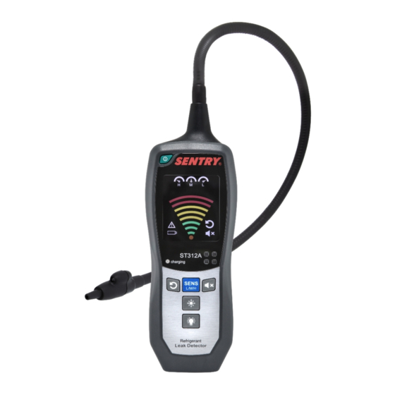
4. General Descriptions 4-1. Parts and Control Panel 1. Power Button 9. Back Light ON/OFF Button 2. Sensitivity Level Indicator 10. Reset/Back Light Indicator 3. Leak Level Indicator 11. Reset Indicator 4. Sensor failure Indicator 12. MuteIndicator 5. Low Battery Indicator 13. - Page 8 4-2.Lithium Battery Storage and Care ●Operating Temperature and Humidity: Discharge : 32°F ~ 122°F(0°C ~ 50°C) ,less than 80% RH Charging : 32°F ~ 113°F(0°C ~ 45°C) ,less than 80% RH ●Storage Humidity: Less than 70% RH ●Storage temperature and capacity recovery: Temperature range Duration Capacity recovery -4°F ~ 139°F (-20°C ~ +60°C)
- Page 9 4-3.Charging the Lithium Battery The detector will automatically turn off if the battery capacity is too low, charging it when the LOW-BATT LED is lit. It is highly recommended not to use the detector during charging, the battery may be heated and dangerous.
- Page 11 5. Operating Instructions 5-1. Main Function 5-1-1 Button Function ● Power Button Turn ON: Press and hold the Power button for 2 seconds to turn the detector on. LCD screen will be lit with the start-up buzzer beep (or, no buzzer beep under MUTE mode).
- Page 12 Manual reset mode: The Reset Indicator on screen disappears and will show for 2 secs. Press the Rest button once to reset to background manually and the Reset Indicator on screen flashes 1 sec. (Only in Manual reset mode.) ...
- Page 13 The tip light is always off after re-start. Press the Tip Light LED Button to turn on/off the light of probe tip. Backlight ON/OFF Button Auto backlight Mode (Power-saving Mode) When no leak activity is found and no buttonis pressedwithin 30secs, the detector will enter Auto backlight Mode (Power-saving Mode) to shutdown LCD backlight.
- Page 14 5-1-3 Sensor Failure Indicator The sensor failure icon blinksand gives slow beep alarm when sensor was misplaced or failure. Please replace a new sensor by section 6-2 or contact your dealer. 5-2. Start with Auto/Manual Reset Mode Manual Reset Mode Inspection 5-2-1 Reset manually to the background level in clear air, and then inspect the possible leak point for at least 0.5 sec.
- Page 15 find the leak point. The manual reset mode can help user to find the leak point more exactly, but it may ※ also easily cause the false-trigger. The auto reset mode provides user with fast and convenient way to find the leak ※...
-
Page 16: Maintenance
6. Maintenance 6-1 Leak Test Bottle Remember to close the seal cap of leak test bottle to avoid evaporating completely after test. 6-2 Probe Tip Replacement of the sensor or Tip Light LED (3V) is shown in the following figure : Note: Turn off the detector before removing sensor.