
Related Manuals for Grizzly G0876


Summary of Contents for Grizzly G0876
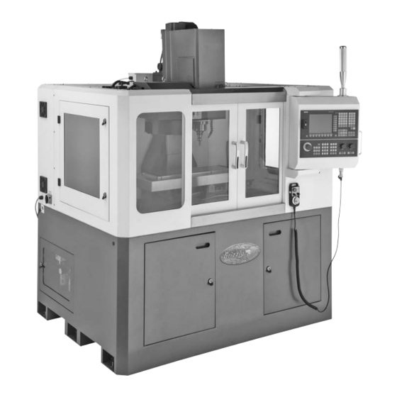
- Page 1 MODEL G0876 8" X 27" ENCLOSED CNC MILL w/AUTO TOOL CHANGER OWNER'S MANUAL (For models manufactured since 3/19)
- Page 2 This manual provides critical safety instructions on the proper setup, operation, maintenance, and service of this machine/tool. Save this document, refer to it often, and use it to instruct other operators. Failure to read, understand and follow the instructions in this manual may result in fire or serious personal injury—including amputation, electrocution, or death.
-
Page 3: Table Of Contents
Table of Contents User interface, machine control panel Machine data sheet ........3 1 Safety Screen arrangement ........40 Elements on the front panel ......41 Safety instructions for machinery ....6 Controls on the control panel ...... 46 Additional safety for CNC mills/lathes .... 8 Protection levels .......... - Page 4 Table of Contents (Cont.) 12 Wiring Diagrams 12.1 Wiring safety instructions ......253 12.2 System wiring diagrams (1-2) ..... 254 12.3 System wiring diagrams (3-4) ..... 255 12.4 System wiring diagrams (5-6) ..... 256 12.4 Handwheel wiring diagram ......252 12.5 X/Y/Z motors wiring diagram ......
-
Page 5: Machine Data Sheet
Customer Service #: (570) 546-9663 · To Order Call: (800) 523-4777 · Fax #: (800) 438-5901 MODEL G0876 8" X 27" ATC ENCLOSED CNC MILL Product Dimensions: Weight ..................................3080 lbs. Width (side-to-side) x Depth (front-to-back) x Height ..................71 x 65 x 79 in. - Page 6 T-Slot Size ................................5/8 in. T-Slots Centers ..............................2-1/2 in. X-Axis Rapid Feed Rate ............................400 IPM Y-Axis Rapid Feed Rate ............................400 IPM Z-Axis Rapid Feed Rate ............................400 IPM Model G0876 (Mfd. Since 3/19) Page 2 of 3 Model G0876...
- Page 7 50–10,000 RPM Spindle Speeds Easy Access to Table from 3 Sides Hands-Free Tool Changes with 8-Position Automatic Tool Changer (ATC) Rapid Table Speeds of Up to 400 in./min. Heavy-Duty BT30 Spindle Model G0876 (Mfd. Since 3/19) Model G0876 Page 3 of 3...
-
Page 8: Safety
Never operate under the influence of drugs or injury or blindness from flying particles. Everyday alcohol, when tired, or when distracted. eyeglasses are NOT approved safety glasses. Model G0876 (Mfd. Since 3/19) - Page 9 Make sure they are properly installed, you experience difficulties performing the intend- undamaged, and working correctly BEFORE ed operation, stop using the machine! Contact our operating machine. Technical Support at (570) 546-9663. Model G0876 (Mfd. Since 3/19)
-
Page 10: Additional Safety For Cnc Mills/Lathes
OFF to avoid ture. Exposure to water creates a shock hazard a possible sudden startup once power is restored. and will reduce life of machine. Model G0876 (Mfd. Since 3/19) -
Page 11: Safety Instructions (Warning Notes)
Practical tips and other important or useful information and notes. No dangerous or harmful consequences for people or objects. INFORMATION In case of specific dangers, we replace the pictogram with general danger by a injury to hands, hazardous electrical rotating warning of voltage, parts. Model G0876 (Mfd. Since 3/19) -
Page 12: Intended Use
If the CNC machine is used in any way other than described above or modified without the express approval of Grizzly Industrial, Inc., then the CNC machine is being used improperly. We will not be held liable for any damages resulting from any operation which is not in accord- ance with the intended use. -
Page 13: Reasonably Foreseeable Misuse
We expressly point out that the guarantee or CE conformity will expire, if any constructive, tech- nicolor procedural changes are not performed by Grizzly Industrial, Inc. It is also part of intended use that you the limits of performance of the CNC machine are observed, ... -
Page 14: Possible Dangers W/Cnc Machines
Unclear responsibilities constitute a safety risk! Always lock the main switch after switching off the CNC machine. This will prevent it from being used by unauthorized persons. The qualifications of the personnel for the different tasks are mentioned below: -12- Model G0876 (Mfd. Since 3/19) - Page 15 We recommend the use of the CNC software SinuTrain as an aid for training and operation. SinuTrain made by Siemens is the perfect software-supplement for the G0876 CNC Mill. This training software supports the rapid training for the operation of the control Sinumerik 808D.
-
Page 16: User Positions
One EMERGENCY STOP push-button on the machine control panel, the milling head and on the electronic handwheel, A locked, separating protective equipment around the CNC milling machine with sight win- dows made of break-proof Makrolon. Locking switch on the separating safety devices. -14- Model G0876 (Mfd. Since 3/19) - Page 17 Img.1-1: Main switch WARNING! Dangerous voltage even if the main switch is switched off. The areas marked by the pictogram might contain live parts, even if the main switch is switched off. -15- Model G0876 (Mfd. Since 3/19)
- Page 18 speed, contact with rotating parts, fatal electrocution, pulling-in of clothes. If you temporarily bypass a controller in exceptional cases (e.g. during electrical repairs), you must continuously monitor the CNC machine. -16- Model G0876 (Mfd. Since 3/19)
-
Page 19: Safety Check
Check Protective housing Switching function, firmly bolted and not damaged Signs, Installed and legible Markers Sight window Check for mechanical damage (scratches, cracks). cracks, "Polycarbonate windows" on page 17 Date: checked by (signature): -17- Model G0876 (Mfd. Since 3/19) -
Page 20: Personal Protective Equipment
- Red light: Actuated emergency stop push button Img.1-3: Signal lamp Safely and firmly clamp the workpiece in place, before switching the CNC machine on. Never change the dosing of the coolant supply during operation. -18- Model G0876 (Mfd. Since 3/19) -
Page 21: Safety During Maintenance
Place a warning sign on the CNC machine. WARNING! Live parts and moves of machine parts can injure you or others dangerously! Proceed with extreme care if you cannot switch off switch due to required works (e.g. functional control). -19- Model G0876 (Mfd. Since 3/19) -
Page 22: Unattended Operation
We provide information about the specific dangers when working with and on the CNC machine in the descriptions for these types of work. 1.17 Electrical system Have the machine and/or the electric equipment checked regularly. Immediately eliminate all defects such as loose connections, defective wires, etc. -20- Model G0876 (Mfd. Since 3/19) -
Page 23: Inspection Deadlines
When using tools with larger diameters or at higher speeds! The balancing of the tools has to amount to 0 - 6000 min - G 6,3 from a speed of 6000 min - G 2,5 according to DIN / ISO 1940. -21- Model G0876 (Mfd. Since 3/19) -
Page 24: Power Supply
To reduce the risk of these hazards, avoid over- loading the machine during operation and make sure it is connected to a power supply circuit that meets the specified circuit requirements. -22- Model G0876 (Mfd. Since 3/19) -
Page 25: Grounding Instructions
-23- Model G0876 (Mfd. Since 3/19) -
Page 26: Assembly And Commissioning
The CNC machine is lifted and transported with an appropriate handling device to the instal- lation place by means of a fork-lift truck. Disassemble the clamping bolts which are used to fix the machine on the pallet. -24- Model G0876 (Mfd. Since 3/19) -
Page 27: Installation And Assembly
Organize the working area around the CNC machine according to the local safety regulations. The working area for operating, maintenance and repair must not be restricted. INFORMATION The main switch of the CNC machine must be freely accessible. -25- Model G0876 (Mfd. Since 3/19) - Page 28 Fix the height adjustment by the the jackscrew with the help of the counternut. Check the alignment of the machine after a few days of usage. -26- Model G0876 (Mfd. Since 3/19)
- Page 29 A corrosion protection is applied on the machine table and on the guiding surfaces for trans- port and storage. Remove the anti-corrosive agent from the CNC machine before first com- missioning. Therefore, we recommend you to use paraffin. -27- Model G0876 (Mfd. Since 3/19)
- Page 30 ATTENTION! Ensure that all 3 phases (L1, L2, L3) and the ground wire are connected correctly. The neutral conductor (N) of its power supply is not connected. -28- Model G0876 (Mfd. Since 3/19)
- Page 31 TN line supply with a grounded line the conductor, e.g. with grounded L1. A TN line system can transfer the neutral conductor N and the PE protective conductor either separately or combined. -29- Model G0876 (Mfd. Since 3/19)
- Page 32 Drip feed lubricator Cylinder tool changer Cylinder tool clamping Cylinder tool clamping Throttle valve Throttle valve Quick exhaust valve Solenoid valve Solenoid valve Compressed air service unit Manometer Air pressure switch Pneumatic oiler Filter Pressure controller -30- Model G0876 (Mfd. Since 3/19)
-
Page 33: First Commissioning
The selection of cooling lubricants and slideway oils, lubricating oils or greases as well as their care are being determined by the machine operator or operating company. Therefore, Grizzly Industrial, Inc. cannot be held liable for machine damages caused by unsuitable coolants and lubricants as well as by inadequate maintenance and servic-ing of the coolant. - Page 34 It should not attack any machine elements (metals, elastomers). Low foaming behaviour of the emulsion. It should be as finely dispersed as possible in order to avoid clogging in the needle slot screen. -32- Model G0876 (Mfd. Since 3/19)
-
Page 35: Refill Central Lubrication System
Img.3-5: Second type of central lubricating system Type: DRB 12210 Pressure 2.0 MPa Power 10 Watt Connection 230V ~ 50Hz / 115V ~ 60Hz filling quantity 1 litres discharge volume 0.08 ml / cycle -33- Model G0876 (Mfd. Since 3/19) - Page 36 Oil is supplied to the lubrication points Idling cycle The red LED flashes Pause between the lubrication cycles The pressure relief valve of the central lubrication system is factory set to a pressure of 2.0 MPa. -34- Model G0876 (Mfd. Since 3/19)
-
Page 37: Functional Test And Controls
If the machine is cold, e.g. directly after having transported the machine, it should be warmed up at a spindle speed of only 500 1/min for the first 30 minutes. -35- Model G0876 (Mfd. Since 3/19) -
Page 38: General Information About Cnc
Such three-dimensional coordinate systems with positive and negative areas on the coordinate axis allow the exact description of any locations, e.g. in the working area of a milling machine, independent from where the zero point of the workpiece is set. -36- Model G0876 (Mfd. Since 3/19) - Page 39 4.2.4 Workpiece coordinate system The workpiece coordinate system is determined by the programmer. It can be changed. The location of the origin point for this workpiece coordinate system, also called workpiece origin point is generally user-defined. -37- Model G0876 (Mfd. Since 3/19)
-
Page 40: Nc Mathmatics
On a rectangular triangle the right angle is described by an quarter circle and a point in the angle. In a rectangular triangle it applies: In a rectangular triangle you can calculate the missing leg if the other leg lengths are known. To do so, use the Pythagorean theorem. -38- Model G0876 (Mfd. Since 3/19) -
Page 41: Trigonometric Functions
Known are: the angle and the length of the adjacent leg Looking for: the length of the opposite leg It applies: tan alpha = opposite leg / adjacent leg The results is: opposite leg = adjacent leg x tan alpha -39- Model G0876 (Mfd. Since 3/19) -
Page 42: User Interface, Machine Control Panel
Alarm and message prompt area Mode Display / Data Display Tip and softkey area Information line Current time and date Horizontal softkey bar Program file name Vertical softkey bar Program status indication Active program control modes -40- Model G0876 (Mfd. Since 3/19) - Page 43 Alphabetic and numeric keys You use these keys to enter characters or NC commands. Holding down <SHIFT> while pressing an alphabetic or numeric key allows you to enter the upper character shown on the key. -41- Model G0876 (Mfd. Since 3/19)
- Page 44 Toggles between the input field and the selected program name. Input key • Confirms your entry of a value. • Opens a directory or program. Alarm cancel key Cancels alarms and messages that are marked with this symbol -42- Model G0876 (Mfd. Since 3/19)
- Page 45 Scrolls upwards on a menu screen Page down key Scrolls downwards on a menu screen Selection key • Toggles in selection lists and selection fields between several options. • Enters the "Set-up menu" dialog at NC start-up. -43- Model G0876 (Mfd. Since 3/19)
- Page 46 Status LEDs LED "RDY" Lights up green: The CNC is ready for operation. LED "TEMP" Unlit: The CNC temperature is within the specified range. Lights up orange: The CNC temperature is out of range. -44- Model G0876 (Mfd. Since 3/19)
- Page 47 Selects text in program blocks. <CTRL> + <C> Copies the selected text. <CTRL> + <D> Shows pre-defined slides on the screen. <CTRL> + <P> Captures screens <CTRL> + <R> Restarts the HMI <CTRL> + <S> Saves start-up archives -45- Model G0876 (Mfd. Since 3/19)
- Page 48 Indicator light On, drive voltage activated • Indicator light Off, drive voltage deactivated Manual tool change Enables or disables the manual tool change. The manual tool change is only possible with the sliding door open. -46- Model G0876 (Mfd. Since 3/19)
- Page 49 Disables the output of setpoints to axes and the spindle. The control system only "simulates" the traverse movements in order to verify the correctness of the program. Conditional stop key Stops the program at every block in which miscellaneous function M01 is programmed. -47- Model G0876 (Mfd. Since 3/19)
- Page 50 LED off: The magazine is not yet referenced. Counterclockwise magazine rotation (active only in JOG mode) Pressing this key rotates the magazine counterclockwise. LED on: The magazine rotates counterclockwise. LED off: The magazine stops counterclockwise rotation. -48- Model G0876 (Mfd. Since 3/19)
- Page 51 LED on: The chip conveyor starts forward rotation. LED off: The chip conveyor stops rotation. INFORMATION The G0876 does not have a chip conveyor. Therefore, the key has no function. Reverse rotation of the chip conveyor (active only in JOG mode) Keeping pressing this key in any operating mode rotates the chip conveyor in reverse order.
- Page 52 Sets increments desired for the axis to traverse. Spindle control keys Starts the spindle counterclockwise Stops the spindle Starts the spindle clockwise Spindle speed override switch Makes the spindle rotate at the specified speed override. Program state keys -50- Model G0876 (Mfd. Since 3/19)
-
Page 53: Protection Levels
Protection level Locked by Area Siemens password Siemens, reserved Manufacturer password Machine manufacturers Reserved 3 - 6 End-user password End users (Default password: "CUSTOMER") No password End users -51- Model G0876 (Mfd. Since 3/19) - Page 54 Change password Press Shift+ System Alarm Delete password Step 2 Enter customer’s or manufacturer’s password. password Change customer’s or manufacturer’s password. Change password Delete Delete customer’s or manufacturer’s password. password -52- Model G0876 (Mfd. Since 3/19)
-
Page 55: Operation
Milling table Signal lamp (if the indicator lamp lights up green --> CNC- program is running) Machine control panel Emergency-stop button Handwheel for manual travelling with Emergency Stop push button and acknowl- edgement button -53- Model G0876 (Mfd. Since 3/19) -
Page 56: Operational Modes
Due to this systematic program structure, the user is able to create a complete program in a short period of time without having any knowledge of the individual program com- mands and their syntax. -54- Model G0876 (Mfd. Since 3/19) -
Page 57: Operation Of The Machine
6.5.2 Reference point approach after turning on INFORMATION After turning on the G0876 must first be referenced. Without existing reference points (machine zero points) you cannot start and run programs in the control. With the beginning of the reference point approach the axes should be located in a central position as possible. - Page 58 After switching on, the G0876 is in the mode reference point approach area, the LED on the <REF POINT> button lights. As long as the axes are not referenced, the symbol (circle) between the axis and the corresponding value is displayed.
- Page 59 . Press the button <OFFSET> to get to the settings. For the following working steps, please proceed as described in „Operation and programming“ of the Siemens SINUMERIK 808D Opera- tion instructions. -57- Model G0876 (Mfd. Since 3/19)
- Page 60 WARNING! A manual movement of axes with open door is not possible. The G0876 has no acknowledgment button to allow movement of axes with open slide door. The lock switch on the slide door may only be unlocked for maintenance and repair work.
- Page 61 Press - if necessary - the push button <K11>. The manual tool change is thereby enabled again. Press the push button "manual tool change" to loosen or to clamp the tool. Push button manual Changing the tool Img.6-3: Spindle head -59- Model G0876 (Mfd. Since 3/19)
- Page 62 Press - if necessary - the push button <K11>. The manual tool change is thereby enabled again. Press the push button "manual tool change" to loosen or to clamp the tool. Push button manual Changing the tool Img.6-5: Spindle head -60- Model G0876 (Mfd. Since 3/19)
-
Page 63: Operational Modes
CAUTION! Before starting the program, the sliding door of the separating protective equipment must be closed. Completely close the separating protective equipment. Change to "AUTO/MDA" mode. -61- Model G0876 (Mfd. Since 3/19) -
Page 64: Central Lubrication System
10 - 25 10 - 22 150 - 350 Plain mill and side milling cutters [ m/min ] Relieved form cutters [ m/min ] 15 - 24 10 - 20 150 - 250 -62- Model G0876 (Mfd. Since 3/19) - Page 65 X5CrNi1810 2) 0.032 0.05 0.063 0.08 0.10 0.10 0.125 0.125 0.16 1): Speed [ n ] in r/min 2): Feed [ f ] in mm/r 3): Cooling: E = Emulsion; oil = cutting oil -63- Model G0876 (Mfd. Since 3/19)
- Page 66 Make sure that the cooling agent is properly retrieved. Respect the environment when dispos- ing of any lubricants and coolants. Follow the manufacturer’s disposal instructions. INFORMATION The CNC milling machine is lacquered with a one-component paint. Observe this fact when selecting your cooling lubricant. -64- Model G0876 (Mfd. Since 3/19)
-
Page 67: Brief Instruction For 808D Milling
MCP mode MCP mode coordinate coordinate Changing system Changing system Passwords Passwords The 808D machine co Moving Moving axis (MCP) is used to selec axis machine operating mo JOG - MDA - AUTO keys -65- Model G0876 (Mfd. Since 3/19) - Page 68 Menu navigation Operating area navigation MCP mode Changing The 808D machine control panel Mode navigation (MCP) is used to select the machine operating mode : JOG - MDA - AUTO -66- Model G0876 (Mfd. Since 3/19)
- Page 69 The 808D machine control panel (MCP) is used to control OEM machine functions. The machine functions can be activated 808D (PPU) has eight h with the appropriate keys. be activated with the cor -67- Model G0876 (Mfd. Since 3/19)
- Page 70 Act. val. Work(WCS) Meas. Meas. Face T,S,M Sett. work. tool cutt. 808D (PPU) has eight horizontal SKs on the bottom of the screen. These SKs can be activated with the corresponding button (located below). -68- Model G0876 (Mfd. Since 3/19)
- Page 71 Step 1 the respective axis. The service mode is ope appropriate key combina In the service mode, th can be activated and de Step 2 password Change password Delete password -69- Model G0876 (Mfd. Since 3/19)
- Page 72 In the service mode, the password Change can be activated and deactivated. password Delete password Step 2 Enter customer’s or manufacturer’s password password Change Change customer’s or manufacturer’s password password Delete customer’s or manufacturer’s password Delete password -70- Model G0876 (Mfd. Since 3/19)
-
Page 73: Switch On And Referencing
Please machin Switch on Switch on the machine Function of machine keyboard Step 1 MCP mode Reference Changing Turn on the main switch o machine Step 2 Make sure you perform th Release buttons -71- Model G0876 (Mfd. Since 3/19) - Page 74 Please note the explicit switching on rules as specified by the machine manufacturer. Step 1 Turn on the main switch of the machine. Step 2 Make sure you perform the following operation! Release all the EMERGENCY STOP buttons on the machine! -72- Model G0876 (Mfd. Since 3/19)
- Page 75 (circle) is displayed between the axis identifier and the value. Step 2 The axes are referenced with the corresponding axis traversing keys. The traversing direction and keys are specified by the machine manufacturer. -73- Model G0876 (Mfd. Since 3/19)
- Page 76 After returning to JOG mode, use the axis traversing keys to move the machine manually. lue. The machine can now be operated in JOG mode. During normal operation (JOG),the referenced symbol is not shown on the screen. -74- Model G0876 (Mfd. Since 3/19)
-
Page 77: Tool Setup
Press “Offset” o Start Create spindle tool Press the “Tool list” SK o Create tool Measure edge tool Machine Load tool into coordinate active spindle system position User Move Execute M machine with interface function handwheel -75- Model G0876 (Mfd. Since 3/19) - Page 78 A tool must have been created and measured tool before executing the program. Step 1 Please make sure the system is in JOG mode. Press “Offset” on the PPU. Tool Press the “Tool list” SK on the PPU. list -76- Model G0876 (Mfd. Since 3/19)
- Page 79 Press the “OK” SK on the PPU. Enter the ”Radius” of the milling tool. Tool Tool list wear Press the “Edge Press the “New edg Press the “Input” button on the PPU. -77- Model G0876 (Mfd. Since 3/19)
- Page 80 Radius edge Reset edge Delete edge Back Work Tool Tool User offset var. data list wear data Press the “Edges” SK on the PPU. Edges Press the “New edge” SK on the PPU. edge -78- Model G0876 (Mfd. Since 3/19)
- Page 81 A maximum of nine tool edges can be created for each tool! Different tool lengths and radii can be saved in different tool edges as required. Please select the right tool edge for machining according to requirement! -79- Model G0876 (Mfd. Since 3/19)
- Page 82 Other M function Back to activate above functions. Press ´CYCLE START´ Meas. Meas. Face Sett. tool work. cutt. Press “CYCLE START” on the MCP dges as Press the “Back” SK on the PPU back -80- Model G0876 (Mfd. Since 3/19)
- Page 83 Select the axis you want to move with the appropriate keys. on the MCP Under “WCS” or “MCS” state, a handwheel will be shown beside the axis symbols, showing the axis is chosen, and can be controlled with a handwheel. -81- Model G0876 (Mfd. Since 3/19)
- Page 84 MCP for selecting the axis of handwheel, the user will have to activate “Handwheel” function with PPU softkey. Handwheel n beside hosen, Handwheel Select the required axis on Axis Number the right of the PPU; the selected axis is shown with a √ -82- Model G0876 (Mfd. Since 3/19)
- Page 85 Activate zerooffset Other M function Back Press the “Mea Press ´CYCLE START´ to activate above functions. Meas. Meas. Face Sett. tool cutt. work. Press the “Measure m Press the “CYCLE START” key on the MCP -83- Model G0876 (Mfd. Since 3/19)
- Page 86 Press the “Machine” key on the PPU Press the “JOG” key on the MCP Meas- Press the “Meas. tool” SK on the PPU tool Measure Press the “Measure manual” SK on the PPU manual -84- Model G0876 (Mfd. Since 3/19)
- Page 87 Z0 or The measured tool length the workpiece. length value column of the Step 2 Measure diam Press the Move directly to zero point Use a setting block. -85- Model G0876 (Mfd. Since 3/19)
- Page 88 The measured tool length is now shown in “Length (L)”. This value is also saved in the length value column of the corresponding tool list at the same time. Step 2 Measure diameter Press the “Diameter” SK on the PPU Diameter -86- Model G0876 (Mfd. Since 3/19)
- Page 89 Meas. work. Press the ”Set Press the “Handwheel” key on the MCP and position the tool at the location X0 or of the workpiece. Press Move directly to zero point Use a setting block. -87- Model G0876 (Mfd. Since 3/19)
- Page 90 X0/Y0 according to requirement.) Workpiece edge Tool measurement manual diameter Diameter Back Meas. Meas. Face Sett. work. cutt. tool Press the ”Set diameter” SK on the PPU diameter Press the “Back” SK on the PPU back -88- Model G0876 (Mfd. Since 3/19)
- Page 91 Press “Spindle stop” on the MCP to stop the Activate zerooffset spindle. Other M function Press ´CYCLE START´ Press “Spindle right” on the MCP to start the spindle in the clockwise direction. Press “CY The coolant functio Press the “Reset” k Press -89- Model G0876 (Mfd. Since 3/19)
- Page 92 Press “CYCLE START” on the MCP. The coolant function button on MCP is active. Press the “Reset” key on the MCP to stop the coolant function. Press the “Back” SK on the PPU. -90- Model G0876 (Mfd. Since 3/19)
-
Page 93: Workpiece Setup
Press Press th Create workpiece offset Ente Test tool Select “M3” using th offset results T,S,M T,S,M Tool change Spindle speed Spindle direction Activate zerooffset Other M function Press ´CYCLE START´ Press the “CYCL -91- Model G0876 (Mfd. Since 3/19) - Page 94 Tool change Spindle speed Spindle direction Activate zerooffset Other M function Back Press ´CYCLE START´ to activate above functions. Meas. Meas. Face Sett. tool work. cutt. Press the “CYCLE START” key on the MCP -92- Model G0876 (Mfd. Since 3/19)
- Page 95 Press t Press “Reset” on the MCP to stop the spindle rotation Press the “Me Press the “Back” SK on the PPU As the following red fram tools to simplify the oper Meas. T,S,M work. -93- Model G0876 (Mfd. Since 3/19)
- Page 96 Press the “Meas. work.” SK on the PPU. Meas. work. As the following red frame shows, 808D provides the user with three methods of using tools to simplify the operating process. Back Meas. Meas. Face T,S,M Sett. cutt. work. tool -94- Model G0876 (Mfd. Since 3/19)
- Page 97 Press the axis traverse keys to move the tool to the required setting position in the X axis. Press the “Set “Step 2” must be repea If you change the tool b must remeasure the len -95- Model G0876 (Mfd. Since 3/19)
- Page 98 “Step 2” must be repeated for the setting of Y and Z zero points. If you change the tool because of wear/damage during the machining process, you must remeasure the length of the tool. -96- Model G0876 (Mfd. Since 3/19)
- Page 99 Save P4 Work offset rectangular workpiece. Offset Offset Compensation data have been act Meas. T,S,M work. Compensation data have been activated! Back Meas. Face Meas. Sett. T,S,M work. tool cutt. -97- Model G0876 (Mfd. Since 3/19)
- Page 100 Workpiece measurement, center of circle point of the workpiece as the as the Work offset center point of the circular workpiece. rkpiece. Offset Compensation data have been activated! Back Meas. Meas. Face T,S,M Sett. tool cutt. work. -98- Model G0876 (Mfd. Since 3/19)
- Page 101 Make sure the feedrate override on the MCP is at 0%! Press “CYCLE START” on the MCP. Increase the feedrate override gradually to avoid accidents caused by an axis moving too fast. Observe whether the axis moves to the set position. -99- Model G0876 (Mfd. Since 3/19)
-
Page 102: Create Part Program: Part 1
Return to change to User User Imperial and Behaviors at Setting a delay T, F, S function interface Metric system interface corners in the program Geometry data / mo Return to change to End/stop motion -100- Model G0876 (Mfd. Since 3/19) - Page 103 N75 S3000 M3 G94 F100 N80 G00 X50 Y50 Z5 Geometry data / motion N85 G01 Z-5 N90 Z5 Return to change tool N95 G00 Z500 D0 N100 G00 G40 G53 X0 Y0 Z500 D0 End/stop motion -101- Model G0876 (Mfd. Since 3/19)
- Page 104 Step 3 Create a new program with the “New” SK on the right of the PPU. Name Type Length Date Time Execute The system will save it a -102- Model G0876 (Mfd. Since 3/19)
- Page 105 Cancel key to open file, [DEL] key to delete file Step 5 Now the program is opened and can be edited. The system will save it automatically after editing. -103- Model G0876 (Mfd. Since 3/19)
- Page 106 With G70 at the heade Execute the geometry data will in the imperial (inches) Renumber unit system, the feedra in the default metric Search system. Mark Copy Paste Edit Cont. Drill. Mill. Sin. Activate comp. -104- Model G0876 (Mfd. Since 3/19)
- Page 107 (inches) N15 S5000 M3 G94 F300 unit system, the feedrate in the default metric N20 G00 X3.93 Y3.93 Geometry data / motion system. N25 G01 Z-0.787 Z0.196 Return to change tool N35 G00 Z19.68 -105- Model G0876 (Mfd. Since 3/19)
- Page 108 N10 T1 D1 M6 value in G500 will be N15 S5000 M3 G94 F300 added to the value in G500 Y G54. N20 G00 G54 X20 Y20 Z5 N25 G01 Z-20 N35 G00 G53 Z500 -106- Model G0876 (Mfd. Since 3/19)
- Page 109 N20 G00 X3.93 Y3.93 Z0.196 Finally you should change the N25 G01 G91 Z-0.787 program to absolute positioning with G94 F300 Z0.196 G90. N35 G00 Z19.68 G94 F300 20 Y20 Z5 -107- Model G0876 (Mfd. Since 3/19)
- Page 110 When G01 is activated in N30 Z5 machines with automatic gram, the axis will traver N35 G00 Z500 D0 tool changer. programmed feed rate in line, according to the fee defined by G94 or G95. -108- Model G0876 (Mfd. Since 3/19)
- Page 111 When G01 is activated in the pro- gram, the axis will traverse at the programmed feed rate in a straight Straight line (parallel/ line, according to the feed rate type unparallel to axis) defined by G94 or G95. -109- Model G0876 (Mfd. Since 3/19)
- Page 112 Arrow indicates the direction of tool motion along the contour. -110- Model G0876 (Mfd. Since 3/19)
- Page 113 The result of the two commands will be such that the cutter goes very fast around a corner motion or slow on the contour. -111- Model G0876 (Mfd. Since 3/19)
- Page 114 Two common types of defining circles and arcs: G3 = define circle :G02/G03 X_Y_I_J_; ① :G02/G03 X_Y_CR=_; ② Arcs ≤180º,CR is a positive number Arcs >180º,CR is negative number When milling circles, you can only use to define the program! ① -112- Model G0876 (Mfd. Since 3/19)
- Page 115 J = defined relative increment from start point to center point in Y G2 = define circle direction in traversing direction = G2 clockwise G3 = define circle direction in traversing direction = G3 counter-clockwise -113- Model G0876 (Mfd. Since 3/19)
- Page 116 N25 G01 Z-5 interface in the program N30 Z5 G74 Z=0 ;reference point can be used to pa tools’ movements durin G75 X=0 ;fixed point operation F5: Program paus This makes the surface workpiece much smoot -114- Model G0876 (Mfd. Since 3/19)
- Page 117 N25 G01 Z-5 N30 G04 F5 F5: Program pause of 5 s N35 Z5 M4 This makes the surface of the N40 M5 workpiece much smoother N45 M19 N35 G00 Z500 D0 -115- Model G0876 (Mfd. Since 3/19)
-
Page 118: Create Part Program: Part 2
CHR = Chamfer (specified side length o Contour milling Hole triangle with chamfer a with cycle centering CHF=Chamfer (specified base line len isosceles triangle with Milling slots Drilling base line) and spigots holes Tapping actual effect -116- Model G0876 (Mfd. Since 3/19) - Page 119 N95 G01 F300 Z-10 actual effect N100 G41 Y 90 N102 G01 X 5 N105 G01 X12 RND=5 N110 G01 Y97 CHR=2 N115 G01 X70 RND=4 N120 G01 Y90 N125 G01 G40 X80 N130 G00 Z50 -117- Model G0876 (Mfd. Since 3/19)
- Page 120 “Center drilling” ,and parameterize the cycle according to requirements. Modal call N325 MCALL CYCLE82 Cancel N330 X20 Y20 ; Hole w N335 X40 Y40 ; Hole w N340 MCALL N345 X60 Y60 ; Hole w -118- Model G0876 (Mfd. Since 3/19)
- Page 121 N325 MCALL CYCLE82( 50.000, -3.000, 2.000, -5.000, 0.000, 0.200) Cancel N330 X20 Y20 ; Hole will be centered N335 X40 Y40 ; Hole will be centered N340 MCALL N345 X60 Y60 ; Hole will not be centered -119- Model G0876 (Mfd. Since 3/19)
- Page 122 N325 MCALL CYCLE83 90.00000, 0.70000, 0.50 Modal N330 X20 Y20 ; Hole wi call N335 X40 Y40 ; Hole wi Cancel N340 MCALL N345 X60 Y60 ; Hole wi -120- Model G0876 (Mfd. Since 3/19)
- Page 123 90.00000, 0.70000, 0.50000, 1.00000, 0, 0, 5.00000, 1.40000, 0.60000, 1.60000) Modal N330 X20 Y20 ; Hole will be drilled call N335 X40 Y40 ; Hole will be drilled Cancel N340 MCALL N345 X60 Y60 ; Hole will not be drilled -121- Model G0876 (Mfd. Since 3/19)
- Page 124 DTD <0:unit is r, DTD DAM=2 depth for 0.6 s =0:same as DTB DIS1=1.6 When reinserting a quill, you can For specific explanations program a distance limit of 1.6 mm please refer to the standard handbook -122- Model G0876 (Mfd. Since 3/19)
- Page 125 (FDPR-2DAM)-DAM Remaining depth =10 < e plane =6-2=4 2xFDPR, the remaining depth cides distribute by the last two drilling (FDPR-3DAM)-DAM ates only =4-2=2 DAM=2 value is DAM=2 value is DAM=2 DAM=2 DAM=2 andard -123- Model G0876 (Mfd. Since 3/19)
- Page 126 SKs on the right. Rigid Thread → tapping Retract plane, absolute Select “Thread” using the vertical SKs ,and then select “Rigid tapping”, and parameterize the cycle according to requirement. Modal call Cancel -124- Model G0876 (Mfd. Since 3/19)
- Page 127 With the “Modal call” SK, holes will be tapped at subsequently programmed positions until cancelled with the MCALL command in the part program. Examples are shown on the next page . Modal call Cancel -125- Model G0876 (Mfd. Since 3/19)
- Page 128 5 r/m N330 X20 Y20 ; Hole will be tapped SST1=5 Retra N335 X40 Y40 ; Hole will be tapped N340 MCALL N345 X60 Y60 ; Hole will not be tapped synch feed actual effect -126- Model G0876 (Mfd. Since 3/19)
- Page 129 SST and SST1 control the spindle speed and the Z axis feed position synchronously. During execution of CYCLE 84, the switches of the feed rate override and the cycle stop (feed hold) are deactivated. -127- Model G0876 (Mfd. Since 3/19)
- Page 130 Circl Hole Hole → pattern circle STA1=90 Angl Select “Hole pattern” INDA=60 Angl using the vertical SKs NUM=6 Drill ,and then select “Hole circle”, and parameterize the cycle according to the h requirement. Cancel -128- Model G0876 (Mfd. Since 3/19)
- Page 131 Angle between the circle and horizontal coordinate is 90º INDA=60 Angle between the circles is 60º NUM=6 Drill 6 holes on circle The cycle is used together with the drilling fixed cycle to decrease the hole clearance. Cancel -129- Model G0876 (Mfd. Since 3/19)
- Page 132 Name of contour subroutine The “Contour milling” SK can be found in the file vertical SKs on the right. Attach contour Contour milling The parameterization is performed as in this figure. Cancel Edit Cont. -130- Model G0876 (Mfd. Since 3/19)
- Page 133 Make sure that the cursor has moved to the contour writing file position (as shown in the Attach contour figure). Search Mark Copy Paste Cancel Tech Edit Cont. interface -131- Model G0876 (Mfd. Since 3/19)
- Page 134 Press “Technical interface” on the PPU to return to the interface for setting the cycle data. After finishing the parameter settings of CYCLE72, press the ”OK” SK on the PPU to insert the corresponding cycles in the main program. -132- Model G0876 (Mfd. Since 3/19)
- Page 135 After all the settings take effect, the selected cycle and set data will be transferred to corresponding part program automatically (for further information, see next page). -133- Model G0876 (Mfd. Since 3/19)
- Page 136 N245 CYCLE72( "SUB_PART_1", 50.00000, 0.00000, 2.00000, -5.00000, 5.00000, 0.00000, 0.00000, 300.00000, 100.00000, 111, 41, 12, 3.00000, 300.00000, 12, 3.00000) cont RL=41(absolute value) cont AS1=12 circl LP1=3 20 m FF3=300 path AS2=12 Retu in sp LP2=3 -134- Model G0876 (Mfd. Since 3/19)
- Page 137 Return along the 1/4 circle on the path Parameter explanations in space are the same as for AS1 LP2=3 The radius of the return circle is 20 The length of the returning path is along the line to approach -135- Model G0876 (Mfd. Since 3/19)
- Page 138 “Mill.” SK. actual effect The relevant cycle can be found using the vertical SKs on the right. Circumf. Slots → slots Select “slot” using the vertical SKs and parameterize the cycle according to requirement. -136- Model G0876 (Mfd. Since 3/19)
- Page 139 With the “OK” SK, the values and cycle call will be transferred to the part program as shown below. This will perform milling at the position defined in the cycle. actual effect -137- Model G0876 (Mfd. Since 3/19)
- Page 140 For descriptions of RTP, RFP, SDIS, DP and DPR, please see Page 119 FFCP Feed ra For descriptions of CPA, CPO and RAD, please see Page 129 path ,un For descriptions of FFD and FFP1, please see Page 135 Before r -138- Model G0876 (Mfd. Since 3/19)
- Page 141 If FFP2/SSF are not specified, then use the feed rate/spindle speed of rotation as default FFCP Feed rate at the center position on the circle path ,unit is mm/min Before recalling the cycle, you must set the tool radius compensation value. -139- Model G0876 (Mfd. Since 3/19)
- Page 142 Create Part Program Part 2 -140- Model G0876 (Mfd. Since 3/19)
- Page 143 -141- Model G0876 (Mfd. Since 3/19)
-
Page 144: Simulate Program
(Axis Description do not move) This unit describes how to simulate a part program before executing it in AUTO mode. Content Step 1 The part program must Simulate program (Axis do not move) -142- Model G0876 (Mfd. Since 3/19) - Page 145 A part program must have been created before program (Axis it can be tested using “Simulation”. do not move) UTO mode. Step 1 The part program must be opened using the “Program Manager” on PPU. -143- Model G0876 (Mfd. Since 3/19)
- Page 146 If this message is displayed at the bottom of the screen, press the “AUTO” mode key on the MCP. Press the “Edit” SK on -144- Model G0876 (Mfd. Since 3/19)
- Page 147 Press the “Edit” SK on the PPU to return to the program. -145- Model G0876 (Mfd. Since 3/19)
-
Page 148: Test Program
This unit describes how to simulate a part program before executing it in AUTO mode. Execution Content Program Execution Press the “ Dry Run The control is no current opened pr displayed and the A Now the pr operation w -146- Model G0876 (Mfd. Since 3/19) - Page 149 The control is now in AUTO mode with the current opened program storage path being displayed and the AUTO lamp on the MCP is Now the program is ready to start and the actual operation will be described in the next section! -147- Model G0876 (Mfd. Since 3/19)
- Page 150 (If you don’ the doo Enter the required feedrate in mm/min, enter “2000 ” in the example. Press “CYCLE STA Turn the feedra After finishin to the origin Press the “Input” key of the PPU. machining! -148- Model G0876 (Mfd. Since 3/19)
- Page 151 Turn the feedrate override gradually to the required value. After finishing the dry run, please turn the changed offset back to the original value in order to avoid affecting the actual machining! -149- Model G0876 (Mfd. Since 3/19)
-
Page 152: Machine Pieces
This unit describes how to use the Time counter function and how to machine pieces and Counter the compensation setting for the tool wear. Content Step 1 Press the Time Press Counter Press the “Tim Piece- Machining User Tool Wear interface -150- Model G0876 (Mfd. Since 3/19) - Page 153 Make sure the machine has been referenced before Counter machining workpieces! Step 1 Press the “Machine” key on the PPU. Press the “Auto” key on the MCP. Press the “Time counter” SK on the PPU. -151- Model G0876 (Mfd. Since 3/19)
- Page 154 (or select the M01 fun Notes:M01 function → there is M01 code. Make sure Press “Door” on the M you don’t use this fun Press “CYCLE STA -152- Model G0876 (Mfd. Since 3/19)
- Page 155 Press “Door” on the MCP to close the door of the machine. (If you don’t use this function, just close the door on the machine manually.) Press “CYCLE START” on the MCP to execute the program. -153- Model G0876 (Mfd. Since 3/19)
- Page 156 Set the tool radius we Press the “Auto” key on the MCP. wear compensation. Positive value: tool is Negative value: tool is Use the direction keys to select the required tools and their edges. Press “Input” on the -154- Model G0876 (Mfd. Since 3/19)
- Page 157 Positive value: tool is away from workpiece (set radius bigger than real one) Negative value: tool is close to workpiece (set radius smaller than real one) Press “Input” on the PPU to activate the compensation. -155- Model G0876 (Mfd. Since 3/19)
-
Page 158: Program Restart
Content Press th Pres Press the “B Block Search Press the “Interr. p cursor will move to Note: The cursor can program block with th Press the “ (can also p -156- Model G0876 (Mfd. Since 3/19) - Page 159 “To end point”: The program will continue from the line with the breakpoint. Press the “To end point” SK on the PPU. (can also press “To contour” if required) -157- Model G0876 (Mfd. Since 3/19)
- Page 160 Make sure the correct tool is selected before continuing! Press the “CYCLE START” key on the MCP to execute the program. Alarm 010208 is shown at the top prompting to press the “CYCLE START” key to continue the program. -158- Model G0876 (Mfd. Since 3/19)
- Page 161 Press the “CYCLE START” key on the MCP to execute the program. Turn the feedrate override on the MCP gradually to the required value. RT” key to -159- Model G0876 (Mfd. Since 3/19)
-
Page 162: Additional Information: Part 1
SW on the PC. RS232 + USB Press “Pro parameters Press Time Shared Network change Drive (only ADVANCED) Press th Save Help data Adjust the parameters communication SW o Manual face Gear cutting change Pres Pres -160- Model G0876 (Mfd. Since 3/19) - Page 163 Press the “Settings” SK on the PPU. Adjust the parameters in “Communication settings” to match the settings of communication SW on PC. Press the “Save” SK on the PPU. Press the “Back” SK on the PPU. -161- Model G0876 (Mfd. Since 3/19)
- Page 164 The PPU will display a window showing the progress of the transfer. Check the interface set from PC. (Press ”Send Data” on The PPU will display a If there is a problem during transfer of the part program, a window will be displayed. -162- Model G0876 (Mfd. Since 3/19)
- Page 165 Check the interface setting and start the communication software to send the program from PC. (Press ”Send Data” on SINUCOM PCIN to send data.) The PPU will display a window showing the progress of the transfer. splayed. -163- Model G0876 (Mfd. Since 3/19)
- Page 166 Use “Cursor + Select” to select the required part program. The selected program will be highlighted. Press the “Copy” SK on the PPU. Press "Netw Press the “NC” SK on the PPU. Press the “Paste” SK on the PPU. -164- Model G0876 (Mfd. Since 3/19)
- Page 167 Connect PC using a network cable to the rear X130 ethernet port on the PPU Press key: Press key: Press “Serv. Displ.” SK Press “Serv. Displ.” SK rom NC to ace on the Press "Network Info" button to enter the "Local Configuration Data" -165- Model G0876 (Mfd. Since 3/19)
- Page 168 When the "data storage end" is Select "OK" to complet displayed, the input data activation effect. Note: The address "10. on the first step in the I PPU and PC IP addres same network segmen -166- Model G0876 (Mfd. Since 3/19)
- Page 169 Select "OK" to complete the setup. Note: The address "10.10.10.2" setting is based on the first step in the IP address of the PPU. PPU and PC IP address should be kept in the same network segment. -167- Model G0876 (Mfd. Since 3/19)
- Page 170 In this folder you can put some machining program. Add the network drive on the PPU side to activate the shared folder, and Step 4 online processing In the “Network drive configuration” screen select “Net drv. Config.” -168- Model G0876 (Mfd. Since 3/19)
- Page 171 Press “Add Drive” SK to add it to the specified drive letter After set successful, the screen will displayed “Network drive added successfully” while the set path is automatically written to the “drive” Window. der, and g.” -169- Model G0876 (Mfd. Since 3/19)
- Page 172 Press “netwo. Drive” SK to enter the network drive Press the “Cycle Start” interface. button for machining operation. Press “Enter” Button to open network drive to PC/PG. Note: You can also use Drive” moving files. -170- Model G0876 (Mfd. Since 3/19)
- Page 173 AUTO mode, select the appropriate NC program. Press the “Cycle Start” button for machining operation. Note: You can also use the “Copy”, “Paste” key to achieve “NC”, “USB” and “Network Drive” moving files. -171- Model G0876 (Mfd. Since 3/19)
- Page 174 Press the “Input” key o The online help manual of the OEM will be shown on the screen. Press the “TOC” SK on the PPU. The online help from the Siemens manual will be shown. -172- Model G0876 (Mfd. Since 3/19)
- Page 175 Press the “JOG” key on the MCP. Press the “Sett.” SK on the PPU. Enter appropriate values in “Retraction plane” and “Safety distance”. Press the “Input” key on the PPU to activate the settings. -173- Model G0876 (Mfd. Since 3/19)
- Page 176 Make sure that the override value on the MCP is 0%! Press the “Cycle Start” key on the MCP. Adjust the override on the MCP gradually to the required values. -174- Model G0876 (Mfd. Since 3/19)
- Page 177 Programming the STOPRE command in a block will stop block preprocessing and buffering. The following block is not executed until all preprocessed and saved blocks have been executed in full. The preceding block is stopped in exact stop (as with G9). -175- Model G0876 (Mfd. Since 3/19)
- Page 178 N40 G00 X-10.0 Y0 Z10 N50 R1=0 R2=0 R3=0 N60 STOPRE N70 M00 N80 R1=1 N90 STOPRE N100 M00 N110 R2=2 N120 STOPRE N130 M00 N140 R3=R1+R2 N150 STOPRE N160 G00 X=R3 N170 M30 blocks ith G9). -176- Model G0876 (Mfd. Since 3/19)
- Page 179 Press the “HMI” SK on the PPU. “S Save Press the “Date time” SK on the PPU. data Press “Shift” and “Ala Make sure the passwor Press Enter a new “Date” and “Time”. Press the “OK” SK on the PPU. -177- Model G0876 (Mfd. Since 3/19)
- Page 180 Make sure the password is set to the “CUSTOMER” access level. Press the “Save data” SK on the PPU. Press the “OK” SK on the PPU. While the control is saving data to the system, do not operate or switch off the control! -178- Model G0876 (Mfd. Since 3/19)
- Page 181 Gear stage 3 → M43 If the operator is manually selecting the gear stage in the part program, it is the operator’s responsibility to select the correct gear stage according to the required speed. -179- Model G0876 (Mfd. Since 3/19)
-
Page 182: Additional Information: Part 2
Make sure Coordinate User Program function rotation skip interface ROT AROT Press “CYCLE STA Machine Machine Subprogram Turn the feedrate overr coordinate coordinate Scaling Calculator system system User Polar Program coordinates interface example -180- Model G0876 (Mfd. Since 3/19) - Page 183 Make sure the feedrate override on the MCP is at 0%! Press “CYCLE START” on the MCP to execute the MDA program. Turn the feedrate override on the MCP gradually to the required value. -181- Model G0876 (Mfd. Since 3/19)
- Page 184 However, the following r End program and back to Select gear stage the beginning automatically The name can contain le End subprogram M41~M45 Change spindle gear characters long. M3 / M4 / M5 Spindle CW/CCW/Stop Example: LRAHMEN7 -182- Model G0876 (Mfd. Since 3/19)
- Page 185 When you create the program, the program name may be freely selected. However, the following rule should be observed: The name can contain letters, numbers and underscores and should be between 2 and 8 gear characters long. Example: LRAHMEN7 -183- Model G0876 (Mfd. Since 3/19)
- Page 186 Subprograms can be called from a main program, and also from another subprogram. In total, up to eight program levels, including the main program, are available for this type of nested call. -184- Model G0876 (Mfd. Since 3/19)
- Page 187 Starting from the plus direction of X axis and rotates CCW. It is saved and must only be written in blocks in which it changes, after the pole or the plane has been changed. ogram. In his type of -185- Model G0876 (Mfd. Since 3/19)
- Page 188 ; polar coordinate N100 ... AP=26.3 RP=7.344 Z4 ; polar coordinate and Z axis(= cylinder coordinate) Programming example N20 TRANS X20.0 Y15 Point defined by RP, AP RP=... AP=... Pole Example G17: X/Y plane TRAN -186- Model G0876 (Mfd. Since 3/19)
- Page 189 ATRANS X...Y... Z... ; programmable offset, additive to existing offset (incremental) TRANS ; without values, clears old commands for offset rdinate) Programming example N20 TRANS X20.0 Y15.0 programmable offset subprogram call TRANS Y TRANS X... -187- Model G0876 (Mfd. Since 3/19)
- Page 190 ; programmable offset, additive to existing offset (incremental) ; without values, clears old commands for offset If a program contains SC N10 G17 N20 AROT RPL=45 additive 45 degree rotation subprogram call Programming example N10 G17 N20 SCALE X2.0 Y2.0 ATRNS -188- Model G0876 (Mfd. Since 3/19)
- Page 191 If a program contains SCALE or ASCALE, this must be programmed in a separate block. Programming example N10 G17 N20 SCALE X2.0 Y2.0 ; contour is enlarged two times in X and Y subprogram call Workpiece ATRNS X..Y..SCALE X2 Y2 Original Workpiece -189- Model G0876 (Mfd. Since 3/19)
- Page 192 ② enlarge 1.3 times in X and Y N120 ATRANS Y-60 N125 AROT RPL=-10 direction N130 ASCALE X1.3 Y1.3 N135 REPEAT LAB1 LAB N140 In this example, the positive direction of the XY coordinate axis is different when machining each groove! -190- Model G0876 (Mfd. Since 3/19)
- Page 193 Y axis coordinate moves 60 in negative direction AROT RPL=-10 N125 N130 ASCALE X1.3 Y1.3 N130 N135 groove enlarged 1.3 times in the X,Y direction. REPEAT LAB1 LAB2 P1 N135 N140 machining the same groove at the new position N140 -191- Model G0876 (Mfd. Since 3/19)
- Page 194 GOTOF+ label: Jump forward (in the direction of the end block of the program) GOTOB+ label:Jump backward (in the direction of the start block of the program) Label: Name of the selected string (standing for the required jump program block) or block number -192- Model G0876 (Mfd. Since 3/19)
- Page 195 This requires a N70 LABEL0: R1=R2+R3 N80 GOTOF LABEL1; jumps to label LABEL1 N90 LABLE2: M30; program ends lock) or N110 LABEL1: N130 GOTOB LABEL2 ;jumps to label LABEL2 Unconditional jump example -193- Model G0876 (Mfd. Since 3/19)
- Page 196 Using “;” code to add a string will be skipped without remark to the N85 function, execution. without any influence on the execution. When ”SKP” is display After activating “SKP”, purple circle), the strin -194- Model G0876 (Mfd. Since 3/19)
- Page 197 When ”SKP” is displayed (red circle), the skip function has been activated. After activating “SKP”, using “/” at the beginning of the program string (shown in purple circle), the string will be skipped without influencing the execution. -195- Model G0876 (Mfd. Since 3/19)
- Page 198 Use this SK editor, tool offsets and workpiece offsets and enter the results on the screen. position. If the input value into th Use the “Ac Press the “=“ SK on the PPU. cursor posit automatical -196- Model G0876 (Mfd. Since 3/19)
- Page 199 If the input field is already occupied by a value, the calculator will take this value into the input line. Use the “Accept” SK to enter the result in the input field at the current cursor position of the part program editor. The calculator will then close automatically. -197- Model G0876 (Mfd. Since 3/19)
-
Page 200: Sample Program
This unit shows three typical program examples of frequently used milling cycles and the program 1 corresponding machining diagrams with detailed explanations. Content Milling program 1 Milling program 2 Machine Milling coordinate program 3 system Tool information: T1 Milling tool D50 T2 Milling tool D8 -198- Model G0876 (Mfd. Since 3/19) - Page 201 1 have been performed before machining! The zero point of the workpiece is located at the center point of the workpiece Tool information: T1 Milling tool D50 T2 Milling tool D8 -199- Model G0876 (Mfd. Since 3/19)
- Page 202 X axis is 0º), feedrate 300 mm/min, milling direction G2, rough machining, use G1 vertical groove center to insert. ; ==Adaptive rotation around Z axis== N180 rotation in positive direction 90º N190 _END: Milling end sign -200- Model G0876 (Mfd. Since 3/19)
- Page 203 N230~N260 operation three times N280 cancel all the coordinate rotation commands hing=== ; =====Cancel rotation=========== pth 5 mm, ius 4 mm, 6), angle e X axis is tion G2, ve center to º -201- Model G0876 (Mfd. Since 3/19)
- Page 204 X axis in positive direction is 45º, angle between the holes is 60º, circular hole number 6 →) N400 cancel mode use N410 Tool information: T1 Milling tool D50 T2 Milling tool D12 T4 Milling tool D10 -202- Model G0876 (Mfd. Since 3/19)
- Page 205 3 mm ALL” mode to decided by nate(X0,Y0), with first hole s in positive es is 60º, Tool information: T1 Milling tool D50 T2 Milling tool D12 T4 Milling tool D10 -203- Model G0876 (Mfd. Since 3/19)
- Page 206 N180 N190 N200 G42 activate tool radius compensation N210 starts from (X44,Y-2) insert a reverse circle, radius is 2 mm N220 (X22,Y0) is the reverse circle point N230 G40 cancel tool radius compensation N240 -204- Model G0876 (Mfd. Since 3/19)
- Page 207 X finishing rface m/min, use e G1 to do along a ters of approach are ompensation eter 10 mm ensation everse circle, oint nsation -205- Model G0876 (Mfd. Since 3/19)
- Page 208 ; ========Path milling en Tool information T1 Milling tool D50 T5 Milling tool D5 T2 Milling tool D12 T6 Drilling tool D10 T3 Milling tool D10 T7 Drilling tool D5 T4 Milling tool D16 T8 Tap D6 -206- Model G0876 (Mfd. Since 3/19)
- Page 209 ; ========Path milling end======== N200 left side radius compensation N210 circle, milling radius is 5 mm N220 incline, milling side length is 2 mm N230 N240 N250 cancel tool radius compensation N260 ; =========Path milling end====== -207- Model G0876 (Mfd. Since 3/19)
- Page 210 300 mm/min, plane machining feedrate 300 mm/min, milling direction G3, slot edge finishing allowance 0.2 mm, complete machining ways, finishing machining feedrate 250 mm/min, spindle speed rate 3000 r/min ; ========Slot milling end======= -208- Model G0876 (Mfd. Since 3/19)
- Page 211 90º, machining, use G1 vertical groove center to insert. , plane N570 repeat N600 milling process, the difference g direction is the machining allowance. m, complete ; ==Rectangular pocket milling end== edrate 250 -209- Model G0876 (Mfd. Since 3/19)
- Page 212 10 mm, start angle 90º, angle between the holes is 60º, circular hole number 6 N770 continue drilling with (X36,Y24.1) as the center point N780 cancel mode recall instruction ; =========Drilling end=========== -210- Model G0876 (Mfd. Since 3/19)
- Page 213 1.4 G17 G90 DIAMOF sert lead G0 X7 Y0 G1 Y61.35 G2 X13.499 Y86 I=AC(57) J=AC(61.35) 10 mm, start G1 X63 RND=2 60º, circular M2;/* end of contour */ 1) as the -211- Model G0876 (Mfd. Since 3/19)
-
Page 214: Iso Mode
808D ISO mode. Content ISO function switch Method 1 Press the “Shift” + “ Input the manu function switch Pres ISO code explanation A dialog box appe the new setting ISO program transfer and operation -212- Model G0876 (Mfd. Since 3/19) - Page 215 Press the “Shift” + “System - Alarm” keys on the PPU. Input the manufacturer’s password (“SUNRISE”) Press the “ISO mode” SK on the right. A dialog box appears prompting whether to activate the new setting. Select the “OK” SK to activate it. -213- Model G0876 (Mfd. Since 3/19)
- Page 216 , R Rever G291/G290 before commands must be set separately M3/M4/M5 Spind in a line! M98 P _L_ Subpr End o If ISO is displayed at the top of the screen, it is activated. -214- Model G0876 (Mfd. Since 3/19)
- Page 217 Reverse circle (note the form there must be ”, ” before R parameter) s must arately M3/M4/M5 Spindle right / spindle left / spindle stop As DIN M98 P _L_ Subprogram call (P+ subprogram name/ L+ times) Program name End of Subroutine -215- Model G0876 (Mfd. Since 3/19)
- Page 218 G04 X2.0 ;delay 2 s Circles greater than 180° a Y-550 ;after orientation drilling, back to values start point → ② G02 X6.0 Y2.0 R-50 ;cancel the fixed cycle N70 M5 ;spindle rotation stop N80 M30 -216- Model G0876 (Mfd. Since 3/19)
- Page 219 Circles less than 180° is assigned positive values Y=50mm → ① G02 X6.0 Y2.0 R50.0 End point Circles greater than 180° are assigned negative g, back to X6.0 Y 2.0 values → ② G02 X6.0 Y2.0 R-50.0 Start point Y=50mm -217- Model G0876 (Mfd. Since 3/19)
- Page 220 Retraction motion(+Z G87 / G89 In 808D, the default ISO program feed distance unit is mm! (X100→100mm) → → Note: change the parameter 10884 = 0, to make X100 100 um / X100. 100 mm -218- Model G0876 (Mfd. Since 3/19)
- Page 221 ;after orientation drill 5th hole, back to R point G98 Y750 ;after orientation drill 6th hole, back to R point G80 ;cancel fixed cycle G28 G91 X0 Y0 Z0 ;back to reference point ;spindle rotation stop -219- Model G0876 (Mfd. Since 3/19)
- Page 222 Y-550 ;after orientation drill 5th hole, back to R point ③ Retraction motion (+Z) → G98 Y-750;after orientation drill 6th hole, back to start plane ;cancel fixed cycle G28 G91 X0 Y0 Z0 ;back to reference point ;spindle rotation stop -220- Model G0876 (Mfd. Since 3/19)
- Page 223 Retraction motion (+Z) → fast feed o start plane G98 Y-750. ;after orientation drill 6th hole, back to start plane ;cancel fixed cycle G28 G91 X0 Y0 Z0 ;back to reference point ;spindle rotation stop -221- Model G0876 (Mfd. Since 3/19)
- Page 224 Motion at the bottom of the hole → Motion at the bottom of t none pause ③ ③ Retraction motion (+Z) → cutting feed Retraction motion (+Z) → feed Origin R point Z point -222- Model G0876 (Mfd. Since 3/19)
- Page 225 Except that the spindle stops at the bottom of the hole, same as ② Motion at the bottom of the hole → pause ③ Retraction motion (+Z) → cutting feed Origin R point Z point Pause -223- Model G0876 (Mfd. Since 3/19)
- Page 226 A specified ISO progr executed as describe spindle start Origin Make the Step 2 spindle start R point Programs changes m Z point Z point the ISO pr Using G98 Using G99 spindle stop spindle stop -224- Model G0876 (Mfd. Since 3/19)
- Page 227 Programs in ISO mode in the 808D have their own rules. Suitable changes must be made at the appropriate positions so that you can run oint the ISO programs! dle stop -225- Model G0876 (Mfd. Since 3/19)
- Page 228 H list in the tool list is open. Note: Every tool only can use the H value corresponding to the edge. In the graphic above, T2 H1 cannot be executed. A specified ISO progra -226- Model G0876 (Mfd. Since 3/19)
- Page 229 Press the “USB” SK on the PPU. Press the “Paste” SK on the PPU. A specified ISO program is then stored in the USB and can be executed as required. -227- Model G0876 (Mfd. Since 3/19)
- Page 230 N140 X50,R10 N150 Y-50,R10 N160 X40 N170 X0 N180 G03X-20Y-70R20 N190 G1G40X0 N200 G0Z50 Note: This program o with the G291/G290 c recommended to use open ISO mode — us active button on the P -228- Model G0876 (Mfd. Since 3/19)
- Page 231 Note: This program opens/exits ISO mode N440 G290 with the G291/G290 command. It is N450 M30 recommended to use the first method to open ISO mode — using the ISO mode active button on the PPU (described above) -229- Model G0876 (Mfd. Since 3/19)
-
Page 232: Appendix
Group 1: Modally valid Name Meaning Functions Rapid tra G01 * Linear int Circular i Circular i Circular i Circular i Thread c G331 Thread in G332 Thread in Group 2: Non-modally v -230- Model G0876 (Mfd. Since 3/19) Name Meaning... - Page 233 SAR - Retract with a straight line G247 SAR - Approach with a quadrant G248 SAR - Retract with a quadrant G347 SAR - Approach with a semicircle G348 SAR - Retract with a semicircle -231- Model G0876 (Mfd. Since 3/19)
- Page 234 Name Meaning Group 12: Exact stop w G40 * Tool radius compensation OFF Name Meaning Tool radius compensation left of contour G601 * Exact stop Tool radius compensation right of contour G602 Exact stop -232- Model G0876 (Mfd. Since 3/19)
- Page 235 Continuous — path mode Group 11: Exact stop, non-modal Name Meaning Non-modal exact stop Group 12: Exact stop window modally effective Name Meaning G601 * Exact stop window G602 Exact stop window, course, with G60, G9 -233- Model G0876 (Mfd. Since 3/19)
- Page 236 Group 16: Feedrate override modally effective Name Meaning CFC * Feedrate override with circle ON CFTCP Feedrate override OFF Group 18: Behavior at corner when working with tool radius compensation Name Meaning G450 * Transition circle G451 Point intersection -234- Model G0876 (Mfd. Since 3/19)
- Page 237 Approach and retraction in the plane (SAR) Group 47: External NC languages modally effective Name Meaning G290 * Siemens mode G291 External mode Transformations Name Meaning TRACYL Cylinder. Peripheral surface transformation TRANSMIT Transmit: Polar transformation TRAFOOF Deactivate transformation -235- Model G0876 (Mfd. Since 3/19)
-
Page 238: Code List, M Functions
Stopping the milling spindle Automatic tool change Cooling lubricant pump ON Cooling lubricant pump OFF Return from subroutine Spindle stop in defined limit position Program end with resetting (Reset) Clamp workpiece Loosen workpiece Workpiece change -236- Model G0876 (Mfd. Since 3/19) - Page 239 Function Function -237- Model G0876 (Mfd. Since 3/19)
-
Page 240: G Functions To Pal
Travelling in rapid feed in polar coordi- nates Linear interpolation with polar coordinates Circular interpolation clockwise with polar coordinates Circular interpolation anti-clockwise with polar coordinates Linear tangential travelling on a contour Linear tangential travelling off the contour Accurate stop off -238- Model G0876 (Mfd. Since 3/19) -
Page 241: Notes, Messages, And Errors
PROGRAMMED TOOL NUM. > MAX. TURRET NUMBER 700024 Max. tool number setting error 700025 NO POSITION SIGNALS FROM TURRET 700026 Not able to find expected tool in monitor time 700027 APPROACH REF.POINT AGAIN AFTER ROT. MONITORING -239- Model G0876 (Mfd. Since 3/19) - Page 242 700057 User alarm 58 700058 User alarm 59 700059 safety door not closed, NC start not possible 700060 Channel not in reset, change PRT not possible 700061 User alarm 62 700062 User alarm 63 -240- Model G0876 (Mfd. Since 3/19)
- Page 243 Number Message 700063 User alarm 64 700064 User alarm 65 700065 User alarm 66 700066 User alarm 67 700067 User alarm 68 700068 User alarm 69 -241- Model G0876 (Mfd. Since 3/19)
-
Page 244: Sinumerik 808D
German, English, Russian, Portuguese and Chinese language. http://support.automation.siemens.com For any questions regarding the CNC control, please contact: Siemens AG, A&D techsupport Phone (+49) 0180 50 50 222 mailto: techsupport@ad.siemens.de Siemens AG Hotline, Helpline Phone (+49) 0180 50 50 111 -242- Model G0876 (Mfd. Since 3/19) -
Page 245: Maintenance
The CNC milling machine is lacquered with a one-component paint. Take this criterion into account when selecting your cooling lubricant. Grizzly Industrial, Inc. does not assume any guarantee for subsequent damages due to unsuitable cooling lubricants. The flashpoint of the emulsion must be higher than 140°C. -243-... -
Page 246: Safety
The selection of cooling lubricants and slideway oils, lubricating oils or greases as well as their care are being determined by the machine operator or operating company. Therefore, Grizzly Industrial, Inc. cannot be held liable for machine damages caused by unsuitable coolants and lubricants as well as by inadequate maintenance and servicing of the coolant. - Page 247 Before restarting, run a safety check. "Safety check“ on page 17 WARNING! Before starting the CNC machine, you must check that there is no danger for persons and that the CNC machine is not damaged. -245- Model G0876 (Mfd. Since 3/19)
-
Page 248: Inspection And Maintenance
See also Fill level control "Cool-ing lubricants“ on page 243 3.5 “Refill central lubrication system“ on page 33 Check the oil level in the oil collecting gutter. Empty Empty the oil collecting tank. -246- Model G0876 (Mfd. Since 3/19) - Page 249 Check the drive belt on wear and excessive clear- ance. Readjusting If required, readjust the gear belt and/or replace it. Replacing Check if coupling is worn and check coupling Check slack. check Replace If necessary, replace the coupling. -247- Model G0876 (Mfd. Since 3/19)
- Page 250 Damaged, scratched or even broken polycarbonate sight windows must be replaced immediately. A soft cloth should be used to clean the machine safety glass. We recommend that the polycarbonate sight windows in the door is changed 60 months after commissioning of the CNC machine. -248- Model G0876 (Mfd. Since 3/19)
-
Page 251: Sliding Door Interlock Switch
The interlock switch can be mechanically unlock for repair and maintenance purposes. Perform a safety check if you have set the interlock switch back to the ground state. "Safety check“ on page 17 Unlocking Img.11-1: Interlock switch sliding door -249- Model G0876 (Mfd. Since 3/19) - Page 252 Check the water level daily and drain the water level in the filter if necessary. Drainage Img.11-2: Compressed air service unit -250- Model G0876 (Mfd. Since 3/19)
-
Page 253: Cooling Lubricants And Tanks
Never dump oil or other substances which are harmful to the environment into water inlets, riv- ers or channels. Used oils must be delivered to a collection centre. Consult your supervisor if you do not know where the collection centre is. -251- Model G0876 (Mfd. Since 3/19) - Page 254 Use water from the public grid if there is of the preparation water, if tory method water from the pubic grid has this is not removed from > 50 mg/l nitrate: Inform the waterworks the public grid -252- Model G0876 (Mfd. Since 3/19)
-
Page 255: Wiring Safety Instructions
EXPERIENCING DIFFICULTIES. If you are expe- the requirements at the beginning of this manual riencing difficulties understanding the information when connecting your machine to a power source. included in this section, contact our Technical Support at (570) 546-9663. -253- Model G0876 (Mfd. Since 3/19) -
Page 256: System Wiring Diagrams (1-2)
R1 S1 T1 System Wiring Diagram (2) Fan/Lubricate 24V Power 5SJ6 1038 AC230 AC400 1.5mm2black AC220 (SP FAN) DC24 0.5mm2blue 5SJ6 1047 5SJ6 1027 5SJ6 1047 24P1 24P2 24P3 READ ELECTRICAL SAFETY -254- Model G0876 (Mfd. Since 3/19) ON PAGE 253! -
Page 257: System Wiring Diagrams (3-4)
Slow Slow Slow Tool-No Forward Tool Tool Door Alarm Tool Overload Orientation Backward Ready 24P1 0.5mm2blue (21) (24) X– Y– Z– TPP ATCT ATC0 DOOR X100 X101 X102 READ ELECTRICAL SAFETY -255- Model G0876 (Mfd. Since 3/19) ON PAGE 253! -
Page 258: System Wiring Diagrams (5-6)
N0 NC N0 NC N0 NC N0 NC N0 NC System Wiring Diagram (6) 15 A+ 808D CNC AGND Main Motor Drive ENCODER 24P3 N0 NC N0 NC READ ELECTRICAL SAFETY -256- Model G0876 (Mfd. Since 3/19) ON PAGE 253! -
Page 259: Handwheel Wiring Diagram
Air Pressure X301 – A – B X100 /COM /LED /LED HANDWHEEL 24P1 X/Y/Z Motors Wiring Diagram X Drive Y Drive Z Drive 24P1 24P1 24P1 X126 808D CNC READ ELECTRICAL SAFETY -257- Model G0876 (Mfd. Since 3/19) ON PAGE 253! -
Page 260: Parts
PARTS We do our best to stock replacement parts when possible, but we cannot guarantee that all parts shown are available for purchase. Call (800) 523-4777 or visit www.grizzly.com/parts to check for availability. Housing BUY PARTS ONLINE AT GRIZZLY.COM! -258- Model G0876 (Mfd. - Page 261 P08760018 DOOR WINDOW SUB-FRAME (SIDE) P08760038 HANDHELD CONTROLLER PENDANT RICHAUTO P08760019 WINDOW SUB-FRAME (FRONT LEFT) P08760039 CONTROLLER PANEL CORD P08760020 SLIDING DOOR SUB-FRAME BUY PARTS ONLINE AT GRIZZLY.COM! -259- Model G0876 (Mfd. Since 3/19) Scan QR code to visit our Parts Store.
-
Page 262: Base
LUBRICANT PUMP MOUNTING PLATE P08760123 CHIP DRAWER P08760111 HINGE HL019 P08760124 EXT RETAINING RING 7MM P08760112 SCREEN P08760125 BEARING SUPPORT P08760113 SHAFT BUY PARTS ONLINE AT GRIZZLY.COM! -260- Model G0876 (Mfd. Since 3/19) Scan QR code to visit our Parts Store. -
Page 263: Milling Head
CAP SCREW M10-1.5 X 45 P08760205 MILLING SPINDLE P08760212 MOTOR MOUNT P08760206 CAP SCREW M8-1.25 X 25 P08760213 BELT P08760207 MOUNTING PLATE BUY PARTS ONLINE AT GRIZZLY.COM! -261- Model G0876 (Mfd. Since 3/19) Scan QR code to visit our Parts Store. -
Page 264: Milling Table
LINEAR GUIDE P08760310 LINEAR GUIDE SLIDE P08760305 CAP SCREW M5-.8 X 20 P08760311 CAP SCREW M4-.7 X 12 P08760306 MOUNTING PLATE BUY PARTS ONLINE AT GRIZZLY.COM! -262- Model G0876 (Mfd. Since 3/19) Scan QR code to visit our Parts Store. -
Page 265: X-Axis
P08760406 EXT RETAINING RING P08760414 BEARING BLOCK P08760407 ANGULAR CONTACT BEARING 7002 P08760415 CAP SCREW M8-1.25 X 25 P08760408 MOUNTING FLANGE BUY PARTS ONLINE AT GRIZZLY.COM! -263- Model G0876 (Mfd. Since 3/19) Scan QR code to visit our Parts Store. -
Page 266: Y-Axis
BALL BEARING 6001-2RS P08760514 Y-AXIS SERVO MOTOR P08760507 EXT RETAINING RING 28MM P08760515 CAP SCREW M5-.8 X 16 P08760508 EXT RETAINING RING 12MM BUY PARTS ONLINE AT GRIZZLY.COM! -264- Model G0876 (Mfd. Since 3/19) Scan QR code to visit our Parts Store. -
Page 267: Z-Axis
EXT RETAINING RING 17MM P08760617 CAP SCREW M8-1.25 X 35 P08760608 CAP SCREW M8-1.25 X 25 P08760618 SPACER P08760609 BEARING BLOCK BUY PARTS ONLINE AT GRIZZLY.COM! -265- Model G0876 (Mfd. Since 3/19) Scan QR code to visit our Parts Store. -
Page 268: Column
Column BUY PARTS ONLINE AT GRIZZLY.COM! -266- Model G0876 (Mfd. Since 3/19) Scan QR code to visit our Parts Store. - Page 269 P08760717 CAP SCREW M5-.8 X 8 P08760736 SHAFT P08760718 PLATE P08760737 HOLDER P08760719 CAP SCREW M16-2 X 60 P08760738 CABLE CARRIER BUY PARTS ONLINE AT GRIZZLY.COM! -267- Model G0876 (Mfd. Since 3/19) Scan QR code to visit our Parts Store.
-
Page 270: Auto Tool Changer
P08760807 ATC TOOL HOLDER P08760817 MANIFOLD P08760808 PLATE P08760818 BASE PLATE P08760809 COVER P08760819 GUIDE ROD PLATE P08760810 P08760820 PNEUMATIC CYLINDER BUY PARTS ONLINE AT GRIZZLY.COM! -268- Model G0876 (Mfd. Since 3/19) Scan QR code to visit our Parts Store. -
Page 271: Electrical Cabinet
CASTER 3" FIXED P08760910 SIDE COVER P08760922 EYE BOLT M10-1.5 X 20 P08760911 P08760923 TRANSFORMER LUHO JB/T8750 230V-400V P08760912 SWITCH SUPPORT BUY PARTS ONLINE AT GRIZZLY.COM! -269- Model G0876 (Mfd. Since 3/19) Scan QR code to visit our Parts Store. -
Page 272: Pneumatic System
CYLINDER TOOL CHANGER 1001-4 P08761001-4 LUBRICATOR 1008 P08761008 THROTTLE VALVE 1002 P08761002 PRESSURE SWITCH 1009 P08761009 DRIP LUBRICATOR 1003 P08761003 WAY VALVE BUY PARTS ONLINE AT GRIZZLY.COM! -270- Model G0876 (Mfd. Since 3/19) Scan QR code to visit our Parts Store. -
Page 273: Labels & Cosmetics
Safety labels help reduce the risk of serious injury caused by machine hazards. If any label comes off or becomes unreadable, the owner of this machine MUST replace it in the original location before resuming operations. For replacements, contact (800) 523-4777 or www.grizzly.com. BUY PARTS ONLINE AT GRIZZLY.COM! -271- Model G0876 (Mfd. - Page 275 WARRANTY & RETURNS Grizzly Industrial, Inc. warrants every product it sells for a period of 1 year to the original purchaser from the date of purchase. This warranty does not apply to defects due directly or indirectly to misuse, abuse, negligence, accidents, repairs or alterations or lack of maintenance.