
Related Manuals for Sony Xperia Ion LT28i


Summary of Contents for Sony Xperia Ion LT28i
- Page 1 Working Instructions - mechanical - Sony Xperia Ion LT28at LT28i,LT28h 1261-4718 Rev 6 Sony Mobile Communications AB – Company Internal...
-
Page 2: Table Of Contents
4.18 Audio Jack ..................41 4.19 Gasket Audio Jack ................42 4.20 FPC Side Key ..................44 4.21 Carrier NFC Sub PBA ................. 47 4.22 PBA Sub NFC Assy ................48 1261-4718 Rev 6 Sony Mobile Communications AB – Company Internal 2(108) - Page 3 5.11 SIM Tray & Cover Rear Top ............. 107 Revision History ................. 108 For general information about mechanical repair related issues, refer to 1220-1333: Generic Repair Manual - mechanical 1261-4718 Rev 6 Sony Mobile Communications AB – Company Internal 3(108)
-
Page 4: Exterior Views
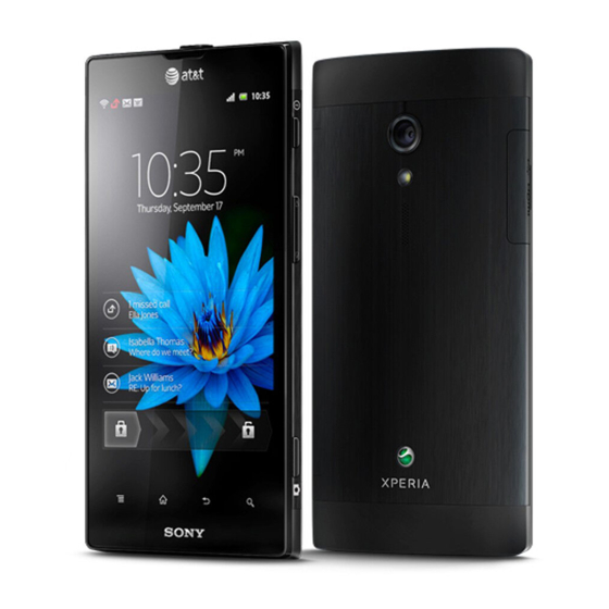
Working Instructions (mech) Exterior Views LT28at 1261-4718 Rev 6 Sony Mobile Communications AB – Company Internal 4(108) -
Page 5: Lt28I, Lt28H
Working Instructions (mech) Exterior Views LT28i, LT28h 1261-4718 Rev 6 Sony Mobile Communications AB – Company Internal 5(108) -
Page 6: Tools
4. Bits (JCIS No 0) 5. Flex Film Assembly Tool 6. Guitar Pick For part no‟s on the tools above, refer to the „Tools Catalogue/Matrix‟! STANDARD TOOLS 1. Dentist Hook 2. Tweezers 1261-4718 Rev 6 Sony Mobile Communications AB – Company Internal 6(108) -
Page 7: Disassembly
Cover Rear Bottom & Label Core Unit Insert a Guitar Pick as shown in picture and gently slide back and forth to release the hooks of the Cover Rear Bottom. 1261-4718 Rev 6 Sony Mobile Communications AB – Company Internal 7(108) -
Page 8: Cover Rear Sub Assy
Scrap! Not to be reused! Remove the two screws M1.4X2.0 on the opposite side by using a screwdriver with Bits (JCIS No 0). Scrap! Not to be reused! 1261-4718 Rev 6 Sony Mobile Communications AB – Company Internal 8(108) - Page 9 Insert a Guitar Pick and gently pull upwards to release the two hooks as shown in picture. Do the same on the opposite side to release the two hooks as shown in picture. 1261-4718 Rev 6 Sony Mobile Communications AB – Company Internal 9(108)
-
Page 10: Key On/Off &Key Camera &Frame Rear Assy &Key Volume
Volume Remove the Key On/Off. Remove the Key camera. Remove the five screws Other Len:4.0 Diam:1.4 by using a screwdriver with Bits (T5). Scrap! Not to be reused! 1261-4718 Rev 6 Sony Mobile Communications AB – Company Internal 10(108) - Page 11 Be careful! Do not damage the Frame Rear Assy! Do the same to release the two hooks as indicated by the arrow. 1261-4718 Rev 6 Sony Mobile Communications AB – Company Internal 11(108)
- Page 12 Be careful! Do not damage the Frame Rear Assy! Insert the Guitar Pick and gently push upwards to release the Frame Rear Assy. Remove the Frame Rear Assy. 1261-4718 Rev 6 Sony Mobile Communications AB – Company Internal 12(108)
-
Page 13: Audio Jack
Gently remove the Audio Jack by using a Flex Film Assembly Tool. Carrier NFC Assy Insert a Guitar Pick and gently pull upwards to release the hooks of the Carrier NFC Assy. 1261-4718 Rev 6 Sony Mobile Communications AB – Company Internal 13(108) - Page 14 Unsnap the BtB connector. Do not damage the components on the Main PBA! Gently remove the switch keys as shown in picture by using a Flex Film Assembly Tool. 1261-4718 Rev 6 Sony Mobile Communications AB – Company Internal 14(108)
-
Page 15: Camera
Use a Front Opening Tool to disconnect the BtB connector. Remove the Camera. Do not touch the lens! Sheet RCV Flex ZIF & FPC Top Flex Assy There are two hooks securing the FPC Top Flex Assy. 1261-4718 Rev 6 Sony Mobile Communications AB – Company Internal 15(108) - Page 16 Insert a Flex Film Assembly Tool from this side to release the hook as shown. Turn the FPC Top Flex Assy over. Gently peel off the Sheet RCV Flex ZIF. Scrap! Not to be reused! 1261-4718 Rev 6 Sony Mobile Communications AB – Company Internal 16(108)
-
Page 17: Carrier Holder Bottom & Sheet Touch Zif & Sheet Lcm Fpc
Carrier Holder Bottom & Sheet Touch ZIF & Sheet LCM Pull outward to release the Carrier Holder Bottom from the hook of this side as shown. Remove the Carrier Holder Bottom. 1261-4718 Rev 6 Sony Mobile Communications AB – Company Internal 17(108) - Page 18 Unlock the ZIF connector by using a Front Opening Tool. Release the touch screen FPC by using a Flex Film Assembly Tool. Unlock the ZIF connector as shown. 1261-4718 Rev 6 Sony Mobile Communications AB – Company Internal 18(108)
- Page 19 Do the same to the other side. Turn it over. Gently peel off the Sheet LCM FPC by using a Flex Film Assembly Tool. Scrap! Not to be reused! 1261-4718 Rev 6 Sony Mobile Communications AB – Company Internal 19(108)
-
Page 20: Fpc Bottom Flex Assy
Use a Flex Film Assembly Tool to release the camera switch as shown. Carefully insert a Dentist Hook as shown in picture to release the FPC from the cavity. Unsnap the BtB connector. 1261-4718 Rev 6 Sony Mobile Communications AB – Company Internal 20(108) - Page 21 There are four snap hooks securing the Sheet Metal Battery Plate Gently lift up to release the four hooks as shown in the picture. Remove the FPC Bottom Flex Assy with fingers. Scrap! Not to be reused! 1261-4718 Rev 6 Sony Mobile Communications AB – Company Internal 21(108)
-
Page 22: Main Pba & Cover Front Assy
Insert a Front Opening Tool as shown in picture and pull upwards to release the hook of this side. Do the same with the hooks of this side as shown. 1261-4718 Rev 6 Sony Mobile Communications AB – Company Internal 22(108) - Page 23 Working Instructions (mech) Disassembly Remove the Main PBA. 1261-4718 Rev 6 Sony Mobile Communications AB – Company Internal 23(108)
-
Page 24: Replacement
Follow the 5.11 Reassembly instructions! Cover Rear Bottom Follow the 3.2 Cover Rear Bottom Disassembly instructions! Prepare a new Cover Rear Bottom. Follow the 5.10 Cover Rear Bottom Reassembly instructions! 1261-4718 Rev 6 Sony Mobile Communications AB – Company Internal 24(108) -
Page 25: Label Core Unit
Cover Rear Bottom. Remove the Cover Rear Bottom. Read the old Mobile Phone Label and write the information into the ‘LabelMake’ program before removal. 1261-4718 Rev 6 Sony Mobile Communications AB – Company Internal 25(108) - Page 26 Attach a new Label Core Unit on its proper position as indicated by the blue lines. Press along to secure its attachment and position. Fold the bottom of the Label Core Unit along the broken line. 1261-4718 Rev 6 Sony Mobile Communications AB – Company Internal 26(108)
- Page 27 Working Instructions (mech) Replacement: Label Core Unit Prepare the Cover Rear Bottom. Place the Cover Rear Bottom on the proper position. Press to snap the hooks. 1261-4718 Rev 6 Sony Mobile Communications AB – Company Internal 27(108)
-
Page 28: Sheet Protection Window
Scrap! Not to be reused! INSTALLATION Clean the touch screen and attach a new Sheet Protection Window on its proper position as shown. Press along to secure its attachment. 1261-4718 Rev 6 Sony Mobile Communications AB – Company Internal 28(108) -
Page 29: Cap Usb Hdmi
REMOVAL Unsnap the hooks of the Cap USB HDMI with fingers as shown in picture. Pull to remove it. INSTALLATION Insert the Cap USB HDMI into the slot. 1261-4718 Rev 6 Sony Mobile Communications AB – Company Internal 29(108) - Page 30 Working Instructions (mech) Replacement: Cap USB HDMI Push it to secure its position. 1261-4718 Rev 6 Sony Mobile Communications AB – Company Internal 30(108)
-
Page 31: Cover Rear Sub Assy
Cover Rear Sub Assy Follow the 3.1 – 3.3 Disassembly instructions! Prepare a new Cover Rear Sub Assy. Follow the 4.8 Installation instructions! Follow the 5.9 – 5.11 Reassembly instructions! 1261-4718 Rev 6 Sony Mobile Communications AB – Company Internal 31(108) -
Page 32: Antenna Nfc Flex
Scrap! Not to be reused! INSTALLATION Place a new Antenna NFC Flex on its proper position as indicated by the guide line. Press along to secure its position. 1261-4718 Rev 6 Sony Mobile Communications AB – Company Internal 32(108) -
Page 33: Key On/Off
Follow the 4.12, 4.15 and 4.6 Installation instructions! Follow the 5.8 – 5.11 Reassembly instructions! The gasket Mic on the Frame Rear Assy must be removed following 4.26 Rubber Mic- removal and installation instruction! 1261-4718 Rev 6 Sony Mobile Communications AB – Company Internal 33(108) -
Page 34: Vibrator
Follow the 5.8 – 5.11 Reassembly instructions! REMOVAL Lift up to remove the Vibrator from the cavity. INSTALLATION Place a new Vibrator in the cavity. Press to secure its position. 1261-4718 Rev 6 Sony Mobile Communications AB – Company Internal 34(108) -
Page 35: Loudspeaker & Adhesive Speaker
Detach to remove the Loudspeaker from the cavity by using a Front Opening Tool. INSTALLATION Place a new Adhesive speaker on the new Loudspeaker. Press to secure its attachment. 1261-4718 Rev 6 Sony Mobile Communications AB – Company Internal 35(108) - Page 36 Place it in the cavity. Note the orientation of the Rubber Conductive GND to be installed! Press to secure its attachment and position. Do not touch the pins! 1261-4718 Rev 6 Sony Mobile Communications AB – Company Internal 36(108)
-
Page 37: Sheet Speaker
Scrap! Not to be reused! INSTALLATION Place a new Sheet Speaker on the Loudspeaker as indicated by the blue rectangle. Press to secure its attachment. Do not touch the pins! 1261-4718 Rev 6 Sony Mobile Communications AB – Company Internal 37(108) -
Page 38: Rubber Conductive Gnd
Remove the Rubber Conductive GND by using a pair of Tweezers. INSTALLATION Insert a new Rubber Conductive GND in the hole. Note the orientation of the Rubber Conductive GND to be installed! Press to secure its position. 1261-4718 Rev 6 Sony Mobile Communications AB – Company Internal 38(108) - Page 39 Working Instructions (mech) Replacement: Rubber Conductive GND There are two Rubber Conductive GNDs. Do the same to the other if need! 1261-4718 Rev 6 Sony Mobile Communications AB – Company Internal 39(108)
-
Page 40: Water Indicator
Detach to remove the Water indicator. Scrap! Not to be reused! INSTALLATION Place a new Water indicator on the correct position as indicated by the guide line. Press to secure its position. 1261-4718 Rev 6 Sony Mobile Communications AB – Company Internal 40(108) -
Page 41: Key Volume
Follow the 5.8 – 5.11 Reassembly instructions! 4.18 Audio Jack Follow the 3.1 – 3.5 Disassembly instructions! Prepare a new Audio Jack. Follow the 5.7 – 5.11 Reassembly instructions! 1261-4718 Rev 6 Sony Mobile Communications AB – Company Internal 41(108) -
Page 42: Gasket Audio Jack
Detach to remove the Gasket Audio Jack. Scrap! Not to be reused! INSTALLATION Attach a new Gasket Audio Jack in the cavity as shown. Press to secure its position. 1261-4718 Rev 6 Sony Mobile Communications AB – Company Internal 42(108) - Page 43 Working Instructions (mech) Replacement: Gasket Audio Jack Peel off the protective film. 1261-4718 Rev 6 Sony Mobile Communications AB – Company Internal 43(108)
-
Page 44: Fpc Side Key
Turn it over and gently detach the FPC of this side as shown. Gently insert the Front Opening Tool as shown to release this side. Scrap! Not to be reused! 1261-4718 Rev 6 Sony Mobile Communications AB – Company Internal 44(108) - Page 45 Working Instructions (mech) Replacement: FPC Side Key Remove it. INSTALLATION Insert a new FPC Side Key into the ZIF connector. Lock it. Press along to secure its position and attachment. 1261-4718 Rev 6 Sony Mobile Communications AB – Company Internal 45(108)
- Page 46 Working Instructions (mech) Replacement: FPC Side Key Push the FPC to turn it over. Press to make it securely attached. 1261-4718 Rev 6 Sony Mobile Communications AB – Company Internal 46(108)
-
Page 47: Carrier Nfc Sub Pba
Scrap! Not to be reused! INSTALLATION Prepare a new Carrier NFC Sub PBA and securely place the PBA Sub NFC Assy on it. Press along to secure its attachment. 1261-4718 Rev 6 Sony Mobile Communications AB – Company Internal 47(108) -
Page 48: Pba Sub Nfc Assy
Follow the 3.1 – 3.6 Disassembly instructions! Prepare a new PBA Sub NFC Assy. Follow the 4.21 and 4.20 Installation instructions! Follow the 5.6 – 5.11 Reassembly instructions! 1261-4718 Rev 6 Sony Mobile Communications AB – Company Internal 48(108) -
Page 49: Camera & Gasket Camera
Insert a Guitar Pick and gently pull upwards to release the hooks of the Carrier NFC Assy. Do the same to release the hook of this side. Turn it over. 1261-4718 Rev 6 Sony Mobile Communications AB – Company Internal 49(108) - Page 50 Unsnap the BtB connector of the Camera. Remove the Camera. INSTALLATION Attach a new Gasket Camera on a new Camera as shown. Press to secure its attachment and position. 1261-4718 Rev 6 Sony Mobile Communications AB – Company Internal 50(108)
- Page 51 Working Instructions (mech) Replacement: Camera & Gasket Camera Press to snap the BtB connector. Gently push it into the cavity. Press to secure its position. Turn it over. 1261-4718 Rev 6 Sony Mobile Communications AB – Company Internal 51(108)
- Page 52 Working Instructions (mech) Replacement: Camera & Gasket Camera Press this side to insert the hooks into the holes. Press to snap the hook of this side. 1261-4718 Rev 6 Sony Mobile Communications AB – Company Internal 52(108)
-
Page 53: Fpc Top Flex
Release this side of the FPC Top Flex from the cavity by using a Front Opening Tool. Unsnap the hook of the FPC Top Flex as shown. Turn it over. 1261-4718 Rev 6 Sony Mobile Communications AB – Company Internal 53(108) - Page 54 Scrap the FPC Top Flex! Not to be reused! INSTALLATION Prepare a new FPC Top Flex and place the Ear Speaker into the cavity. Press to secure its position. Peel off the protective film. 1261-4718 Rev 6 Sony Mobile Communications AB – Company Internal 54(108)
- Page 55 Working Instructions (mech) Replacement: FPC Top Flex Turn it over. Push the FPC into the cavity. Press along to secure its attachment. Press to snap the hook. 1261-4718 Rev 6 Sony Mobile Communications AB – Company Internal 55(108)
-
Page 56: Ear Speaker
Prepare a new Ear Speaker. Follow the 4.24 Installation instructions! Follow the 5.4 – 5.6 Reassembly instructions! Follow the 4.19 Installation instructions! Follow the 5.7 – 5.11 Reassembly instructions! 1261-4718 Rev 6 Sony Mobile Communications AB – Company Internal 56(108) -
Page 57: Rubber Mic
If no Rubber Mic attached on the microphone, skip this step! INSTALLATION Place a new Rubber Mic on the microphone. Note the orientation of the Rubber Mic to be installed! 1261-4718 Rev 6 Sony Mobile Communications AB – Company Internal 57(108) - Page 58 Working Instructions (mech) Replacement: Rubber Mic Press to secure its position. 1261-4718 Rev 6 Sony Mobile Communications AB – Company Internal 58(108)
-
Page 59: Carrier Holder Bottom
Pull outward to release the Carrier Holder Bottom from the hook of this side as shown. Remove the Carrier Holder Bottom. INSTALLATION Insert a new Carrier Holder Bottom into its cavity as shown and secure its position. 1261-4718 Rev 6 Sony Mobile Communications AB – Company Internal 59(108) -
Page 60: Sheet Touch Zif
Scrap! Not to be reused! INSTALLATION Place a new Sheet Touch ZIF on its correct position as indicated by the blue line. Press along to secure its attachment. 1261-4718 Rev 6 Sony Mobile Communications AB – Company Internal 60(108) -
Page 61: Sheet Lcm Fpc
Unlock the ZIF connector by using a Front Opening Tool. Release the touch screen FPC by using a Flex Film Assembly Tool. Unlock the ZIF connector as shown. 1261-4718 Rev 6 Sony Mobile Communications AB – Company Internal 61(108) - Page 62 Do the same to the other side. Turn it over. Gently peel off the Sheet LCM FPC by using a Flex Film Assembly Tool. Scrap! Not to be reused! 1261-4718 Rev 6 Sony Mobile Communications AB – Company Internal 62(108)
- Page 63 Prepare a new Sheet LCM FPC and align it as indicated by the holes. Securely place the Sheet LCM FPC on the Sheet Metal Battery Plate. Press to secure its attachment. Peel off the two protective films. 1261-4718 Rev 6 Sony Mobile Communications AB – Company Internal 63(108)
- Page 64 Insert the LCD FPC into the ZIF connector. Lock it. Press along the two sides of the Sheet LCM FPC to secure its attachment. Insert the touch panel FPC into the ZIF connector. 1261-4718 Rev 6 Sony Mobile Communications AB – Company Internal 64(108)
- Page 65 Working Instructions (mech) Replacement: Sheet LCM FPC Lock it. 1261-4718 Rev 6 Sony Mobile Communications AB – Company Internal 65(108)
-
Page 66: Fpc Bottom Flex & Sheet Metal Battery Plate
Use a Flex Film Assembly Tool to release the camera switch as shown. Carefully insert a Dentist Hook as shown in picture to release the FPC from the cavity. 1261-4718 Rev 6 Sony Mobile Communications AB – Company Internal 66(108) - Page 67 Gently detach the Sheet Metal Battery Plate from the shield can. There are four snap hooks securing the Sheet Metal Battery Plate Gently lift up to release the four hooks of the Sheet Metal Battery Plate. 1261-4718 Rev 6 Sony Mobile Communications AB – Company Internal 67(108)
- Page 68 Insert the two sides into the clip as indicated by the pointers. Securely attached the FPC Bottom Flex on its position as indicated by the holes. Press along to secure its attachment and position. 1261-4718 Rev 6 Sony Mobile Communications AB – Company Internal 68(108)
- Page 69 Working Instructions (mech) Replacement: FPC Bottom Flex & Sheet Metal Battery Plate Peel off the two protective films. Snap the BtB connector. Turn it over. Press to snap the hooks. 1261-4718 Rev 6 Sony Mobile Communications AB – Company Internal 69(108)
- Page 70 Push the FPC into the cavity by using a Flex Film Assembly Tool. Press to secure its position. Push the switch into the cavity as shown in picture. 1261-4718 Rev 6 Sony Mobile Communications AB – Company Internal 70(108)
- Page 71 Do not touch the pads on the FPC! Press to secure its attachment. Gently push the FPC into the cavity by using a Flex Film Assembly Tool. Press along to secure its position. 1261-4718 Rev 6 Sony Mobile Communications AB – Company Internal 71(108)
-
Page 72: Liquid Indicator
Scrap! Not to be reused! INSTALLATION Attach a new Liquid Indicator on the Main PBA as indicated by the golden line. Press to secure its position and attachment. 1261-4718 Rev 6 Sony Mobile Communications AB – Company Internal 72(108) -
Page 73: Rubber Chat Camera
Remove the Rubber Chat Camera with fingers. INSTALLATION Place a new Rubber Chat Camera on the chat camera. Press to secure its attachment. Do not touch the lens! 1261-4718 Rev 6 Sony Mobile Communications AB – Company Internal 73(108) -
Page 74: Shield Can Lid Apq
Scrap! Not to be reused! INSTALLATION Prepare a new Shield Can Lid APQ. Press to snap it. Only the edge of the Shield Can is allowed to press. 1261-4718 Rev 6 Sony Mobile Communications AB – Company Internal 74(108) -
Page 75: Shield Can Lid Charger
Scrap! Not to be reused! INSTALLATION Prepare a new Shield Can Lid Charger. Press to snap it. Only the edge of the Shield Can is allowed to press. 1261-4718 Rev 6 Sony Mobile Communications AB – Company Internal 75(108) -
Page 76: Shield Can Lid Emmc
Scrap! Not to be reused! INSTALLATION Prepare a new Shield Can Lid eMMC. Press to snap it. Only the edge of the Shield Can is allowed to press. 1261-4718 Rev 6 Sony Mobile Communications AB – Company Internal 76(108) -
Page 77: Shield Can Lid Mdm
Scrap! Not to be reused! INSTALLATION Prepare a new Shield Can Lid MDM. Press to snap it. Only the edge of the Shield Can is allowed to press. 1261-4718 Rev 6 Sony Mobile Communications AB – Company Internal 77(108) -
Page 78: Shield Can Lid Non Cell
Scrap! Not to be reused! INSTALLATION Prepare a new Shield Can Lid Non Cell. Press to snap it. Only the edge of the Shield Can is allowed to press. 1261-4718 Rev 6 Sony Mobile Communications AB – Company Internal 78(108) -
Page 79: Shield Can Lid Rf
Scrap! Not to be reused! INSTALLATION Prepare a new Shield Can Lid RF. Press to snap it. Only the edge of the Shield Can is allowed to press. 1261-4718 Rev 6 Sony Mobile Communications AB – Company Internal 79(108) -
Page 80: Foil Adhesive Double Side
Gently detach the PBA Sub Antenna Assy from the cavity by using a Front Opening Tool. Remove it from the cavity with fingers. Gently peel off the Foil Adhesive Double Side. 1261-4718 Rev 6 Sony Mobile Communications AB – Company Internal 80(108) - Page 81 Place a new Foil Adhesive Double Side on the correct position. Press to secure its attachment. Peel off the protective film. Place the PBA Sub Antenna Assy into the cavity as indicated by the pegs and holes. 1261-4718 Rev 6 Sony Mobile Communications AB – Company Internal 81(108)
- Page 82 Working Instructions (mech) Replacement: Foil Adhesive Double Side Press along to secure its attachment. 1261-4718 Rev 6 Sony Mobile Communications AB – Company Internal 82(108)
-
Page 83: Cable Rf
Disconnect this end of the Cable RF. Gently remove the Cable RF from the hooks of the PBA Sub Antenna Assy. INSTALLATION Prepare a new Cable RF and the PBA Sub Antenna Assy. 1261-4718 Rev 6 Sony Mobile Communications AB – Company Internal 83(108) - Page 84 Connect this end of the Cable RF. Insert the Cable RF into the two hooks as shown. Turn the PBA Sub Antenna Assy over and insert the Cable RF into the two hooks. 1261-4718 Rev 6 Sony Mobile Communications AB – Company Internal 84(108)
-
Page 85: Pba Sub Antenna Assy
Prepare a new PBA Sub Antenna Assy. Carry out the Installation as described below. Follow the 4.40 and 4.39 Installation instructions! Follow the 5.1 – 5.11 Reassembly instructions! 1261-4718 Rev 6 Sony Mobile Communications AB – Company Internal 85(108) -
Page 86: Battery 1900Mah & Cover Front Assy
Scrap the Battery 1900mAh and the Cover Front Assy! Not to be reused! INSTALLATION Place a new Battery 1900mAh on the socket. Press along to secure its attachment. 1261-4718 Rev 6 Sony Mobile Communications AB – Company Internal 86(108) -
Page 87: Board Swap - Replacement
Build swap for change of label. 4.45 Board Swap – Customize of Software CUSTOMIZE OF SOFTWARE Follow the instructions in the Generic Repair Manual – Build swap for customization of the software. 1261-4718 Rev 6 Sony Mobile Communications AB – Company Internal 87(108) -
Page 88: Reassembly
Cable RF as shown to make it keep away from the Cover Front Assy. Securely place the corner of the Main PBA onto the pins of the PBA Sub Antenna Assy as shown in picture. 1261-4718 Rev 6 Sony Mobile Communications AB – Company Internal 88(108) -
Page 89: Fpc Bottom Flex Assy
Gently push against the Cable RF to snap it into the hook of the Main PBA. FPC Bottom Flex Assy Follow the 4.29 Installation instructions! Prepare a new FPC Bottom Flex Assy. 1261-4718 Rev 6 Sony Mobile Communications AB – Company Internal 89(108) - Page 90 Working Instructions (mech) Reassembly Snap the BtB connector. Turn it over. Press to snap the hooks. Press along to secure its attachment. 1261-4718 Rev 6 Sony Mobile Communications AB – Company Internal 90(108)
- Page 91 Push the switch into the cavity as shown in picture. Securely place the FPC on its proper position as indicated by the peg and hole. Do not touch the pads on the FPC! 1261-4718 Rev 6 Sony Mobile Communications AB – Company Internal 91(108)
-
Page 92: Sheet Lcm Fpc &Sheet Touch Zif &Carrier Holder Bottom
Press along to secure its position. Sheet LCM FPC &Sheet Touch ZIF &Carrier Holder Bottom Prepare a new Sheet LCM FPC and align it as indicated by the holes. 1261-4718 Rev 6 Sony Mobile Communications AB – Company Internal 92(108) - Page 93 Securely place the Sheet LCM FPC on the Sheet Metal Battery Plate. Press to secure its attachment. Peel off the two protective films. Insert the LCD FPC into the ZIF connector. 1261-4718 Rev 6 Sony Mobile Communications AB – Company Internal 93(108)
- Page 94 Reassembly Lock it. Press along the two sides of the Sheet LCM FPC to secure its attachment. Insert the touch panel FPC into the ZIF connector. Lock it. 1261-4718 Rev 6 Sony Mobile Communications AB – Company Internal 94(108)
-
Page 95: Fpc Top Flex Assy
Press along to secure its attachment. Insert the Carrier Holder Bottom into its cavity as shown and secure its position. FPC Top Flex Assy Prepare the FPC Top Flex Assy. 1261-4718 Rev 6 Sony Mobile Communications AB – Company Internal 95(108) - Page 96 Insert the FPC into the ZIF connector as shown. Lock it. Attach a new Sheet RCV Flex ZIF on the proper position as indicated by the blue rectangle. Press along to secure its attachment. 1261-4718 Rev 6 Sony Mobile Communications AB – Company Internal 96(108)
-
Page 97: Camera
Working Instructions (mech) Reassembly Turn it over. Press to snap the hooks and secure its attachment. Camera Prepare the Camera. Snap the BtB connector. 1261-4718 Rev 6 Sony Mobile Communications AB – Company Internal 97(108) -
Page 98: Carrier Nfc Assy
Do not touch the camera lens! Carrier NFC Assy Follow the 4.20 Removal and Installation instructions to replace a new FPC Side Key! Prepare the new Carrier NFC Assy. Snap the BtB connector. 1261-4718 Rev 6 Sony Mobile Communications AB – Company Internal 98(108) - Page 99 Press this side to insert the hooks into the holes as shown. Press to snap the hook of this side. Securely place the switches on the front unit as indicated by the holes. 1261-4718 Rev 6 Sony Mobile Communications AB – Company Internal 99(108)
-
Page 100: Audio Jack
Press to secure its position. Key Volume &Frame Rear Assy &Key Camera &Key On/Off Place the Key Volume on the proper position. Note the orientation of the Key Volume to be installed! 1261-4718 Rev 6 Sony Mobile Communications AB – Company Internal 100(108) - Page 101 Working Instructions (mech) Reassembly Press it to make it securely mounted. Snap the BtB connector. Place the Frame Rear Assy on the front unit. Press to snap the hooks. 1261-4718 Rev 6 Sony Mobile Communications AB – Company Internal 101(108)
- Page 102 Press the opposite side. Push the Cap USB HDMI to secure its position. Apply 14 ± 2 Ncm torque when tightening the three screws with Bits (JCIS No 0). 1261-4718 Rev 6 Sony Mobile Communications AB – Company Internal 102(108)
- Page 103 Note the orientation of the Key Camera to be installed! Press it to make it securely mounted. Place the Key On/Off on its correct position. Note the orientation of the Key On/Off to be installed! 1261-4718 Rev 6 Sony Mobile Communications AB – Company Internal 103(108)
-
Page 104: Cover Rear Sub Assy
Place the Cover Rear Sub Assy on the front unit. Press to snap the hooks of it. Apply 10 ± 2 Ncm torque when tightening the screw with Bits (JCIS No.0). 1261-4718 Rev 6 Sony Mobile Communications AB – Company Internal 104(108) -
Page 105: Label Core Unit & Cover Rear Bottom
5.10 Label Core Unit & Cover Rear Bottom Attach a new Label Core Unit on its proper position as indicated by the blue lines. Press along to secure its attachment and position. 1261-4718 Rev 6 Sony Mobile Communications AB – Company Internal 105(108) - Page 106 Fold the bottom of the Label Core Unit along the broken line. Prepare the Cover Rear Bottom. Place the Cover Rear Bottom on the proper position. Press to snap the hooks. 1261-4718 Rev 6 Sony Mobile Communications AB – Company Internal 106(108)
-
Page 107: Sim Tray & Cover Rear Top
Insert the SIM Tray into the slot. Push it into the bottom of the slot. Place the Cover Rear Top on the proper position. Push it to snap the hooks. 1261-4718 Rev 6 Sony Mobile Communications AB – Company Internal 107(108) -
Page 108: Revision History
Date Changes / Comments 2012-May-18 Initial release 2012-July-25 Added LT28h 2012-July-27 Update the chapter 4.42 2012-Aug-20 Words adjusted 2012-Aug-30 Update the Board Swap chapter 2012-Sep-6 Added Rubber Mic 1261-4718 Rev 6 Sony Mobile Communications AB – Company Internal 108(108) - Page 109 Test Instructions - mechanical - Sony Xperia Ion LT28at LT28i, LT28h 1261-4720 Rev 2 Sony Mobile Communications AB – Company Internal...
- Page 110 2.2.34 HDMI Test ....................19 2.2.35 Audio Jack test ..................20 2.3 Manual Tests ..................21 2.3.1 SIM ......................21 2.3.2 On/Off key test ................... 21 2.3.3 Home key test .................... 21 1261-4720 Rev 2 Sony Mobile Communications AB – Company Internal 2(25)
- Page 111 2.4 Network Test..................23 2.4.1 On-the-air call to mobile ................23 Revision History ................25 For general information about test procedures, refer to 1220-1333: Generic Repair Manual - mechanical 1261-4720 Rev 2 Sony Mobile Communications AB – Company Internal 3(25)
-
Page 112: Pre-Test Preparations
Cover Rear Top is removed. If affected (red color) - handle the phone according to the local directives. If not affected by liquid, proceed to the ‘Pre-Test Preparation’ below. 1261-4720 Rev 2 Sony Mobile Communications AB – Company Internal 4(25) -
Page 113: Software
(see “Service Types” and “Aspects of large files”) In Swap flow, when change a phone from Customer A to Customer B, always use the service Customization script. 1261-4720 Rev 2 Sony Mobile Communications AB – Company Internal 5(25) -
Page 114: Tests
For more information, refer to 1220-1333: Generic Repair Manual - mechanical SONY The following pictures will show a simplified basic phone for a general visualization of the service tests! 1261-4720 Rev 2 Sony Mobile Communications AB – Company Internal 6(25) -
Page 115: Service Tests
Make sure that there are no missing segments and that the colors and contrast are OK. SONY Press the Back key to return to the Service Test Menu. 1261-4720 Rev 2 Sony Mobile Communications AB – Company Internal 7(25) -
Page 116: Led/Illumination
Press the Back key to return to the Service Test Menu. SONY at&t Stereo speaker 2.2.6 Stereo speaker Left channel is speaking Press the Back key to return to the Service Test Menu. SONY 1261-4720 Rev 2 Sony Mobile Communications AB – Company Internal 8(25) -
Page 117: Earphone
Check the quality by listening to the recording from the Speaker during the ‘Playing recorded sound’ phase at maximum volume. SONY Press the Back key to return to the Service Test Menu. 1261-4720 Rev 2 Sony Mobile Communications AB – Company Internal 9(25) -
Page 118: Vibrator
Aim the camera (located in front of the phone) at an object and check the quality of the image shown in the display. Press the Back key to return to the Service Test Menu. 1261-4720 Rev 2 Sony Mobile Communications AB – Company Internal 10(25) -
Page 119: Flash Led
Device also, when successful, it shows “Test Bluetooth Enable Bluetooth OK Complete”. Searching Devices found Test Complete Press the Back key to return to the Service Test Menu. SONY 1261-4720 Rev 2 Sony Mobile Communications AB – Company Internal 11(25) -
Page 120: Wlan
Enter the GPS Location Test, and wait for the GPS location Purge assistance data data. Press the Back key to return to the Service Test Menu. For GPS testing, refer to 1220-1333: Generic Repair Manual – mechanical SONY 1261-4720 Rev 2 Sony Mobile Communications AB – Company Internal 12(25) -
Page 121: Compass
Front picture. LEFT SIDE Front VIEW BOTTOM VIEW Press the Back key to return to the Service Test Menu. 1261-4720 Rev 2 Sony Mobile Communications AB – Company Internal 13(25) -
Page 122: Gyroscope
Ambient Light Sensor Value:45 when the window gets less light. Press the Back key to return to the Service Test Menu. SONY 1261-4720 Rev 2 Sony Mobile Communications AB – Company Internal 14(25) -
Page 123: Proximity Switch
This test is not available for this product! Proximity switch Pressure Sensor This device does not support the function This device does not support the function Water Proof SONY 1261-4720 Rev 2 Sony Mobile Communications AB – Company Internal 15(25) -
Page 124: Real Time Clock
USB disk shown in picture. The USB Host Mass Storage status is shown on the screen. Press the Back key to return to the Service Test Menu. SONY 1261-4720 Rev 2 Sony Mobile Communications AB – Company Internal 16(25) -
Page 125: Security
OK and red writing and say ‘Bad, need to replace it’ if the battery is not OK. Press the Back key to return to the Service Test Menu. SONY 1261-4720 Rev 2 Sony Mobile Communications AB – Company Internal 17(25) -
Page 126: Flip Slider Counter
Flip slider counter This test is not available for this product! Verify certificates IrDA Test IrDA Test app doesn’t exist IrDA Test app doesn’t exist HDMI Test SONY 1261-4720 Rev 2 Sony Mobile Communications AB – Company Internal 18(25) -
Page 127: Hdmi Test
Note: If the HDMI TV out Monitor doesn’t automatically indentify the picture, the Monitor may require to set the HDMI port chosen as source manually in the Monitors menus. SONY 1261-4720 Rev 2 Sony Mobile Communications AB – Company Internal 19(25) -
Page 128: Audio Jack Test
Repeat the test of “2.2.5 Speaker”, “2.2.7 Earphone” and Speaker “2.2.8 Microphone”. Stereo Speaker Earphone Make sure that the sound from Headset earphone ports are Microphone emitted loud and clear. Stereo Microphone SONY 1261-4720 Rev 2 Sony Mobile Communications AB – Company Internal 20(25) -
Page 129: Manual Tests
2.3.3 Home key test 15:35 Whatever the phone shows now during operation, press the 2010-03-15 Home key for the phone go directly back to the Stand by screen. SONY 1261-4720 Rev 2 Sony Mobile Communications AB – Company Internal 21(25) -
Page 130: Charging Via Usb (Charger Or Computer)
Start, Power key Please leave it Led Light several minutes to decide (up to Continue Trouble ~10 min) Shoot Normal start after Power Charging OK Charging icon 1261-4720 Rev 2 Sony Mobile Communications AB – Company Internal 22(25) -
Page 131: Network Test
End Call verify that the sound level is altered. 7. End the call and check that the elapsed time is displayed and that the termination is done properly. SONY 1261-4720 Rev 2 Sony Mobile Communications AB – Company Internal 23(25) - Page 132 9. Monitor download via task bar if download is completed. 10. Open Settings menu and select “Storage”. 11. Choose “Downloads”. SONY 12. Mark PC Companion files and delete by pressing Recycle Bin icon. 1261-4720 Rev 2 Sony Mobile Communications AB – Company Internal 24(25)
-
Page 133: Revision History
Test Instructions (mech) Revision History Rev. Date Changes / Comments 2012-May-18 Initial release 2012-July-25 Added LT28h 1261-4720 Rev 2 Sony Mobile Communications AB – Company Internal 25(25) - Page 134 Troubleshooting Guide - mechanical - Sony Xperia Ion LT28at LT28i,LT28h 1261-4721 Rev 3 Sony Mobile Communications AB – Company Internal...
- Page 135 1.15.1 Compass fails .................... 35 1.16 Accelerometer ..................36 1.16.1 Accelerometer test fails ................36 1.17 Gyroscope ..................37 1.17.1 Gyroscope test fails .................. 37 1.18 Ambient Light Sensor ................ 38 1261-4721 Rev 3 Sony Mobile Communications AB – Company Internal 2(62)
- Page 136 1.35 HandsFree by Wire ................59 1.35.1 Connection to Portable HandsFree fails ..........59 1.36 Data Communication ................. 61 1.36.1 Data transfer via System Connector fails ..........61 Revision History ................62 1261-4721 Rev 3 Sony Mobile Communications AB – Company Internal 3(62)
-
Page 137: Problem Areas
2. If dirty or oxidized – clean the both sides of the BtB connector. 3. Check current draw in off mode by using “Dummy Battery” (max 1 mA). 1261-4721 Rev 3 Sony Mobile Communications AB – Company Internal 4(62) - Page 138 3. If the key on/off switch, the FPC or the BtB connector of FPC Side Key is damaged – replace the FPC Side Key. 4. Replace board. 1261-4721 Rev 3 Sony Mobile Communications AB – Company Internal 5(62)
-
Page 139: Keys
2. If damaged – replace it. Note: Ensure the BtB connector of battery is disconnected in the following steps! Check: Inspect the key camera switch. Action: If dirty – clean it. 1261-4721 Rev 3 Sony Mobile Communications AB – Company Internal 6(62) -
Page 140: Key Volume
FPC Bottom Flex is damaged – replace the FPC Bottom Flex. 4. Replace board. 1.2.3 Key Volume Check: Inspect the Key Volume. Action: 1. If dirty – clean it. 2. If damaged – replace it. 1261-4721 Rev 3 Sony Mobile Communications AB – Company Internal 7(62) -
Page 141: Key On/Off
FPC Side Key is damaged – replace the FPC Side Key. 4. Replace board. 1.2.4 Key On/Off Check: Inspect the Key On/Off. Action: 1. If dirty – clean it. 1261-4721 Rev 3 Sony Mobile Communications AB – Company Internal 8(62) - Page 142 3. If the key on/off switch, the FPC or the BtB connector of FPC Side Key is damaged – replace the FPC Side Key. 4. Replace board. 1261-4721 Rev 3 Sony Mobile Communications AB – Company Internal 9(62)
-
Page 143: Touch Screen
Inspect the BtB connector of FPC Bottom Flex to the PBA. Action: 1. If not properly connected – disconnect and reconnect. 2. If dirty or oxidized – clean the both sides of the BtB connector. 1261-4721 Rev 3 Sony Mobile Communications AB – Company Internal 10(62) - Page 144 Problem Areas: Touch Screen 3. If the ZIF connector, the BtB connector or FPC of FPC Bottom Flex is damaged – replace the FPC Bottom Flex. 4. Replace board. 1261-4721 Rev 3 Sony Mobile Communications AB – Company Internal 11(62)
-
Page 145: Display
Inspect the BtB connector of FPC Bottom Flex to the PBA. Action: 1. If not properly connected – disconnect and reconnect. 2. If dirty or oxidized – clean the both sides of the BtB connector. 1261-4721 Rev 3 Sony Mobile Communications AB – Company Internal 12(62) - Page 146 Problem Areas: Display 3. If the ZIF connector, the BtB connector or FPC of FPC Bottom Flex is damaged – replace the FPC Bottom Flex. 4. Replace board. 1261-4721 Rev 3 Sony Mobile Communications AB – Company Internal 13(62)
-
Page 147: Led/Illumination
2. If the external window area is damaged – replace the Cover Front Assy. Check: Inspect the RGB LED on the PBA. Action: 1. If dirty or clogged – clean it. 2. Replace board. 1261-4721 Rev 3 Sony Mobile Communications AB – Company Internal 14(62) -
Page 148: Menu, Home, Back, And Search Keys Illumination
Inspect the BtB connector of FPC Bottom Flex to the PBA. Action: 1. If not properly connected – disconnect and reconnect. 2. If dirty or oxidized – clean the both sides of the BtB connector. 1261-4721 Rev 3 Sony Mobile Communications AB – Company Internal 15(62) - Page 149 Problem Areas: Illumination 3. If the ZIF connector, the BtB connector or FPC of FPC Bottom Flex is damaged – replace the FPC Bottom Flex. 4. Replace board. 1261-4721 Rev 3 Sony Mobile Communications AB – Company Internal 16(62)
-
Page 150: Speaker
Inspect the gasket loudspeaker on the Frame Rear Assy. Action: 1. If dirty – clean it. 2. If the gasket is damaged – replace the Frame Rear Assy. 1261-4721 Rev 3 Sony Mobile Communications AB – Company Internal 17(62) - Page 151 Inspect the Loudspeaker‟s pins and the pads on the Main PBA. Action: 1. If dirty – clean them. 2. If the pins of the Loudspeaker are damaged – replace the Loudspeaker. 3. Replace board. 1261-4721 Rev 3 Sony Mobile Communications AB – Company Internal 18(62)
-
Page 152: Earphone
2. If dirty or oxidized – clean it. Check: Inspect the Earspeaker‟s pins and the pads on the FPC Top Flex. Action: 1. If dirty – clean them. 1261-4721 Rev 3 Sony Mobile Communications AB – Company Internal 19(62) - Page 153 2. If the ZIF connector or the pads of FPC Top Flex is damaged – replace the FPC Top Flex. 3. If the pins are damaged – replace the Earspeaker. 4. Replace board. 1261-4721 Rev 3 Sony Mobile Communications AB – Company Internal 20(62)
-
Page 154: Microphone
The gasket Mic(a) must be removed! 2. If there is no Rubber Mic (c) on microphone (b) – assemble a rubber Mic (c) as show in the picture. 1261-4721 Rev 3 Sony Mobile Communications AB – Company Internal 21(62) - Page 155 2. If dirty or oxidized – clean the both sides of the BtB connector. 3. If the BtB connector or the Microphone of FPC Bottom Flex is damaged – replace the FPC Bottom Flex. 4. Replace board. 1261-4721 Rev 3 Sony Mobile Communications AB – Company Internal 22(62)
-
Page 156: Secondary Microphone
Inspect the mesh of the secondary microphone on the Frame Rear Assy. Action: 1. If dirty – clean it. 2. If the mesh is damaged – replace the Frame Rear Assy. 1261-4721 Rev 3 Sony Mobile Communications AB – Company Internal 23(62) - Page 157 2. If dirty or oxidized – clean the both sides of the ZIF connector. 3. If the secondary microphone or the ZIF connector of PBA Sub NFC Assy is damaged – replace the PBA Sub NFC Assy. 1261-4721 Rev 3 Sony Mobile Communications AB – Company Internal 24(62)
- Page 158 Problem Areas: Microphone 4. If the ZIF connector, the BtB connector or FPC of FPC Side Key is damaged – replace the FPC Side Key. 5 Replace board. 1261-4721 Rev 3 Sony Mobile Communications AB – Company Internal 25(62)
-
Page 159: Vibrator
2. If dirty or oxidized – clean the both sides of the BtB connector. 3. If the pads or the BtB connector is damaged – replace the FPC Bottom Flex. 4. Replace board. 1261-4721 Rev 3 Sony Mobile Communications AB – Company Internal 26(62) -
Page 160: Camera
2. If dirty or oxidized – clean both sides of the BtB connector. Check: Inspect the Camera. Action: 1. If the Camera is damaged – replace it. 2. Replace board. 1261-4721 Rev 3 Sony Mobile Communications AB – Company Internal 27(62) -
Page 161: Video Call Camera Defects
Inspect the Rubber Chat Camera. Action: 1. If dirty or clogged – clean it. 2. If not properly mounted – remount it. 3. If damaged – replace it. 4. Replace board. 1261-4721 Rev 3 Sony Mobile Communications AB – Company Internal 28(62) -
Page 162: Flash Led
Inspect the BtB connector of FPC Side Key to the PBA. Action: 1. If not properly connected – disconnect and reconnect. 2. If dirty or oxidized – clean the both sides of the BtB connector. 1261-4721 Rev 3 Sony Mobile Communications AB – Company Internal 29(62) - Page 163 Assy is damaged – replace the PBA Sub NFC Assy. 4. If the ZIF connector, the BtB connector or FPC of FPC Side Key is damaged – replace the FPC Side Key. 5. Replace board. 1261-4721 Rev 3 Sony Mobile Communications AB – Company Internal 30(62)
-
Page 164: Bluetooth And Wlan
Frame Rear Assy and the contact pins on the PBA. Action: 1. If dirty or oxidized – clean the pads and pins. 2. If the pads are damaged – replace the Frame Rear Assy. 3. Replace board. 1261-4721 Rev 3 Sony Mobile Communications AB – Company Internal 31(62) -
Page 165: Nfc
Inspect the ZIF connector of FPC Side Key to the PBA Sub NFC Assy. Action: 1. If not properly connected – disconnect and reconnect. 2. If dirty or oxidized – clean the both sides of the ZIF connector. 1261-4721 Rev 3 Sony Mobile Communications AB – Company Internal 32(62) - Page 166 – replace the PBA Sub NFC Assy. 4. If the ZIF connector, the BtB connector or FPC of FPC Side Key is damaged – replace the FPC Side Key. 5. Replace board. 1261-4721 Rev 3 Sony Mobile Communications AB – Company Internal 33(62)
-
Page 167: Gps
Assy and the contact pins on the PBA. Action: 1. If dirty or oxidized – clean the pads and pins. 2. If the pads are damaged – replace the Frame Rear Assy. 3. Replace board. 1261-4721 Rev 3 Sony Mobile Communications AB – Company Internal 34(62) -
Page 168: Compass
Troubleshooting Guide (mech) Problem Areas 1.15 Compass 1.15.1 Compass fails Action: Replace board. 1261-4721 Rev 3 Sony Mobile Communications AB – Company Internal 35(62) -
Page 169: Accelerometer
Troubleshooting Guide (mech) Problem Areas 1.16 Accelerometer 1.16.1 Accelerometer test fails Action: Replace board. 1261-4721 Rev 3 Sony Mobile Communications AB – Company Internal 36(62) -
Page 170: Gyroscope
Troubleshooting Guide (mech) Problem Areas 1.17 Gyroscope 1.17.1 Gyroscope test fails Action: Replace board. 1261-4721 Rev 3 Sony Mobile Communications AB – Company Internal 37(62) -
Page 171: Ambient Light Sensor
Inspect the light sensor on the FPC Top Flex. Action: 1. If dirty – clean it. 2. If the light sensor or the connector is damaged – replace the FPC Top Flex. 3. Replace board. 1261-4721 Rev 3 Sony Mobile Communications AB – Company Internal 38(62) -
Page 172: Proximity Switch
Action: 1. If dirty – clean it. 2. If the connector, the proximity switch or the proximity sensor damaged – replace the FPC Top Flex. 3. Replace board. 1261-4721 Rev 3 Sony Mobile Communications AB – Company Internal 39(62) -
Page 173: Pressure Sensor
Troubleshooting Guide (mech) Problem Areas 1.20 Pressure Sensor 1.20.1 Pressure Sensor test fails Action: N/A. This test is not applicable for this product. 1261-4721 Rev 3 Sony Mobile Communications AB – Company Internal 40(62) -
Page 174: Water Proof
Troubleshooting Guide (mech) Problem Areas 1.21 Water Proof 1.21.1 Water Proof fails Action: N/A. No water proof functions in the phone. 1261-4721 Rev 3 Sony Mobile Communications AB – Company Internal 41(62) -
Page 175: Real Time Clock
Troubleshooting Guide (mech) Problem Areas 1.22 Real Time Clock 1.22.1 Real Time Clock test fails Action: Replace board. 1261-4721 Rev 3 Sony Mobile Communications AB – Company Internal 42(62) -
Page 176: Total Call Time
Troubleshooting Guide (mech) Problem Areas 1.23 Total call time 1.23.1 Total call time fails Action: Replace board. 1261-4721 Rev 3 Sony Mobile Communications AB – Company Internal 43(62) -
Page 177: External Memory
2. If dirty or oxidized – clean the both sides of the BtB connector. 3. If the memory card holder or the BtB connector of FPC Side Key is damaged – replace the FPC Side Key. 4. Replace board. 1261-4721 Rev 3 Sony Mobile Communications AB – Company Internal 44(62) -
Page 178: Security
Troubleshooting Guide (mech) Problem Areas 1.25 Security 1.25.1 Security fails Action: Replace board. 1261-4721 Rev 3 Sony Mobile Communications AB – Company Internal 45(62) -
Page 179: Fm Radio
Inspect the both sides of the ZIF connector on the Main PBA and the FPC Top Flex. Action: 1. If not properly connected – disconnect and reconnect. 2. If dirty or oxidized – clean it. 1261-4721 Rev 3 Sony Mobile Communications AB – Company Internal 46(62) - Page 180 Troubleshooting Guide (mech) Problem Areas: FM Radio 3. If the pads or the connector of FPC Top Flex is damaged – replace the FPC Top Flex. 4. Replace board. 1261-4721 Rev 3 Sony Mobile Communications AB – Company Internal 47(62)
-
Page 181: Flip Slider Counter
Troubleshooting Guide (mech) Problem Areas 1.27 Flip slider counter 1.27.1 Flip slider counter fails Action: N/A. No slider phone. 1261-4721 Rev 3 Sony Mobile Communications AB – Company Internal 48(62) -
Page 182: Verify Certificates
Troubleshooting Guide (mech) Problem Areas 1.28 Verify Certificates 1.28.1 Verify certificates fails Action: Replace board. 1261-4721 Rev 3 Sony Mobile Communications AB – Company Internal 49(62) -
Page 183: Irda Test
Troubleshooting Guide (mech) Problem Areas 1.29 IrDA Test 1.29.1 IrDA test fails Action: N/A. No IrDA in the phone. 1261-4721 Rev 3 Sony Mobile Communications AB – Company Internal 50(62) -
Page 184: Hdmi Test
Troubleshooting Guide (mech) Problem Areas 1.30 HDMI Test 1.30.1 HDMI test fails Check: Inspect the HDMI connector. Action: 1. If dirty or oxidized – clean the connector. 2. Replace board. 1261-4721 Rev 3 Sony Mobile Communications AB – Company Internal 51(62) -
Page 185: Connector Ground Test
Troubleshooting Guide (mech) Problem Areas 1.31 Connector Ground Test 1.31.1 Connector ground test fails Action: N/A. This test is not applicable for this product. 1261-4721 Rev 3 Sony Mobile Communications AB – Company Internal 52(62) -
Page 186: Network & Signal
Inspect the main antenna contact pin on the PBA Sub Antenna Assy and contact pad on the Frame Rear Assy. Action: If dirty or oxidized – clean the pad and pin. 1261-4721 Rev 3 Sony Mobile Communications AB – Company Internal 53(62) - Page 187 If not properly connected – disconnect and reconnect it. Check: Inspect the connector of Cable RF to the Main PBA. Action: 1. If not properly connected – disconnect and reconnect it. 1261-4721 Rev 3 Sony Mobile Communications AB – Company Internal 54(62)
- Page 188 2. If the connector, the pins or the PBA of PBA Sub Antenna Assy is damaged – replace the PBA Sub Antenna Assy. 3. If the Cable RF is damaged – replace it. 4. Replace board. 1261-4721 Rev 3 Sony Mobile Communications AB – Company Internal 55(62)
-
Page 189: Sim
Inspect the both sides of the ZIF connector on the Main PBA and the FPC Top Flex. Action: 1. If not properly connected – disconnect and reconnect. 2. If dirty or oxidized – clean it. 1261-4721 Rev 3 Sony Mobile Communications AB – Company Internal 56(62) -
Page 190: Incorrect Sim Indicated
Check whether the phone is locked to a particular operator and whether the correct operator SIM is being used. Action: 1. Use a proper operator SIM or test SIM. 2. Replace board. 1261-4721 Rev 3 Sony Mobile Communications AB – Company Internal 57(62) -
Page 191: Charging
2. If dirty or oxidized – clean the both sides of the BtB connector. 3. If the battery or its BtB connector is damaged – replace the Battery 1900mAh. 4. Replace board. 1261-4721 Rev 3 Sony Mobile Communications AB – Company Internal 58(62) -
Page 192: Handsfree By Wire
Inspect the both sides of the ZIF connector on the Main PBA and the FPC Top Flex. Action: 1. If not properly connected – disconnect and reconnect. 2. If dirty or oxidized – clean it. 1261-4721 Rev 3 Sony Mobile Communications AB – Company Internal 59(62) - Page 193 Problem Areas: HandsFree by Wire 3. If the pads or the ZIF connector of FPC Top Flex is damaged – replace the FPC Top Flex. 4. Replace board. 1261-4721 Rev 3 Sony Mobile Communications AB – Company Internal 60(62)
-
Page 194: Data Communication
1.36 Data Communication 1.36.1 Data transfer via System Connector fails Check: Inspect the USB connector. Action: 1. If dirty or oxidized – clean the connector. 2. Replace board. 1261-4721 Rev 3 Sony Mobile Communications AB – Company Internal 61(62) -
Page 195: Revision History
Troubleshooting Guide (mech) Revision History Rev. Date Changes / Comments 2012-May-18 Initial release 2012-July-25 Added LT28h 2012-Sep-6 Update the chapter of Microphone 1261-4721 Rev 3 Sony Mobile Communications AB – Company Internal 62(62) - Page 196 Repair Movies - mechanical - Sony Xperia Ion LT28at LT28i, LT28h 1261-4724 Rev 2 Sony Mobile Communications AB – Company Internal...
- Page 197 In that case, right-click with the mouse on the document name and select Save Target As to download the repair movie document for off-line viewing. For general information about repair movies, refer to 1220-1333: Generic Repair Manual - mechanical 1261-4724 Rev 2 Sony Mobile Communications AB – Company Internal 2(4)
- Page 198 Camera (c) & Key On/Off (d) - Cover Rear Sub Assy - Label Core Unit (a) & Cover Rear Bottom (b) - SIM Tray (a) & Cover Rear Top (b) 1261-4724 Rev 2 Sony Mobile Communications AB – Company Internal 3(4)
- Page 199 Repair Movies (mech) Revision History Rev. Date Changes / Comments 2012-May-18 Initial release 2012-July-25 Added LT28h 1261-4724 Rev 2 Sony Mobile Communications AB – Company Internal 4(4)
- Page 200 Part List - mechanical - Sony Xperia Ion LT28at LT28i,LT28h 1261-4727 Rev 3 Sony Mobile Communications AB – Company Internal...
- Page 201 Part List (mech) CONTENTS Part List ................... 3 Revision History ................10 1261-4727 Rev 3 Sony Mobile Communications AB – Company Internal 2(10)
- Page 202 Audio Jack 1242-3994 Battery 1900mAh 1251-9510 Cable RF 1252-5836 Camera FICTIVE Camera 13.1M 1252-3510 Cap USB HDMI Cap Plastic USB HDMI Black 1252-4188 Cap Plastic USB HDMI Red 1265-6938 1261-4727 Rev 3 Sony Mobile Communications AB – Company Internal 3(10)
- Page 203 Cover Metal Rear Sub Assy Black 1252-4144 Cover Metal Rear Sub Assy Red 1265-6943 Cover Rear Top Cover Plastic Rear Top Black 1252-4151 Cover Plastic Rear Top Red 1265-6933 Ear Speaker 1226-7255 1261-4727 Rev 3 Sony Mobile Communications AB – Company Internal 4(10)
- Page 204 Frame Rear Assy Black RoW 1264-7408 Frame Rear Assy Red RoW 1265-7142 Gasket Audio Jack 1252-4189 Gasket Camera 1256-4462 Key Camera Key Camera 1256-2145 Key Camera Red 1265-6889 1261-4727 Rev 3 Sony Mobile Communications AB – Company Internal 5(10)
- Page 205 Key Volume Red 1265-6891 Label Core Unit 1255-2162 Liquid Indicator 1001-0084 Loudspeaker Loudspeaker 11x15 1001-0324 Sheet LCM FPC 1255-0538 Sheet RCV Flex ZIF 1263-9478 1255-8613 Sheet Touch ZIF 1261-4727 Rev 3 Sony Mobile Communications AB – Company Internal 6(10)
- Page 206 PBA Sub Antenna Assy RoW 1264-7611 PBA Sub NFC Assy 1251-7123 Rubber Chat Camera 1252-4195 Rubber Conductive GND 1261-1491 Rubber Mic 1267-2148 Screw M1.4X2.0 1230-6681 Screw Other Len:3.0 Diam:1.4 1248-2360 1261-4727 Rev 3 Sony Mobile Communications AB – Company Internal 7(10)
- Page 207 Sheet Protection Window (only for ATT) 1248-9107 Sheet Speaker 1252-8531 Shield Can Lid APQ 1252-8233 Shield Can Lid Charger 1252-8241 Shield Can Lid eMMC 1252-8229 Shield Can Lid MDM 1252-8243 1261-4727 Rev 3 Sony Mobile Communications AB – Company Internal 8(10)
- Page 208 Part List (mech) Designation Part No. Part Location Shield Can Lid Non Cell 1252-8235 Shield Can Lid RF 1252-8238 SIM Tray 1263-8998 Vibrator 1245-2711 Water Indicator 1239-5490 1261-4727 Rev 3 Sony Mobile Communications AB – Company Internal 9(10)
- Page 209 Part List (mech) Revision History Rev. Date Changes / Comments 2012-May-18 Initial release 2012-July-25 Added LT28h 2012-Sep-6 Added Rubber Mic 1261-4727 Rev 3 Sony Mobile Communications AB – Company Internal 10(10)
- Page 210 Go/No Go Test - electrical - Sony Xperia Ion LT28at LT28i,LT28h 1261-4732 Rev 3 Sony Mobile Communications AB – Company Internal...
- Page 211 Loss Values – Antenna Coupler CMU-Z11 ..........6 Revision History ................7 LT28i and LT28at all bands is ONLY implemented in CMWrun LT28h. LT28at and LT28i no LTE is ONLY implemented in SERPII. 1261-4732 Rev 3 Sony Mobile Communications AB – Company Internal 2(7)
-
Page 212: Go/No Go Testing
Put the grid positioning holder with its reference point in position G12 and place the phone as shown in the adjacent G H I O P Q R picture. 1261-4732 Rev 3 Sony Mobile Communications AB – Company Internal 3(7) - Page 213 1220-1336: Generic Repair Manual – electrical, together with the ‘Attenuation Factors’ below! This phone is available in tree versions, LT28at, LT28i and LT28h including the following bands: LT28at: GSM-850/900/1800/1900 WCDMA-850/1900/2100 LTE-Band-4/17 LT28i GSM-850/900/1800/1900 WCDMA-850/1700/1900/2100 LTE-Band-4/17 LT28h GSM-850/900/1800/1900 WCDMA-850/900/1700/1900/2100 1261-4732 Rev 3 Sony Mobile Communications AB – Company Internal 4(7)
-
Page 214: Attenuation Factors
17.93 WCDMA 2100 17.29 17.79 High 17.22 17.22 20.54 19.34 24.09 22.59 LTE BAND 4 High 18.95 19.75 7.12 7.12 7.39 7.39 LTE BAND 17 High 6.87 7.67 1261-4732 Rev 3 Sony Mobile Communications AB – Company Internal 5(7) -
Page 215: Loss Values - Antenna Coupler Cmu-Z11
High 14.00 11.83 13.50 12.37 13.50 12.37 13.00 10.41 10.00 10.06 10.00 11.06 WCDMA 2100 12.00 12.51 10.50 11.60 10.50 12.60 High 15.00 12.61 10.50 12.73 10.50 12.73 1261-4732 Rev 3 Sony Mobile Communications AB – Company Internal 6(7) -
Page 216: Revision History
Test and Calibration Repair Instruction Electrical/ Revision History Rev. Date Changes / Comments 2012-May-18 Initial release 2012-June-1 Adjust WCDMA Band2 Mid Channel loss value 2012-Aug-16 LT28h added .LT28i and LT28at no LTE added. 1261-4732 Rev 3 Sony Mobile Communications AB – Company Internal 7(7) - Page 217 Customization - build swap - Sony Xperia Ion LT28at LT28i,LT28h 1266-2375 Rev 2 © Sony Mobile Communications AB – Company Internal...
- Page 218 Customize to Ship ..................7 2.3.2 Build Swap ....................7 Revision History ................8 For general information about Customization and Swap, refer to 1221-5655: Generic Repair Manual – build swap 1266-2375 Rev 2 © Sony Mobile Communications AB – Company Internal 2(8)
-
Page 219: Emma Login & Script Execution
Activation Script’ you will be prompted for the PIN of your USB Activation Dongle you will be prompted for the PIN of your USB Activation Dongle. 1266-2375 Rev 2 © Sony Mobile Communications AB Sony Mobile Communications AB – Company Internal 3(8) -
Page 220: Customization Workflow
Customization Repair Instruction Build Swap Customization Workflow 1266-2375 Rev 2 © Sony Mobile Communications AB – Company Internal 4(8) -
Page 221: Customize Unit
User Guide info. http://emma.extranet.sonyericsson.com/documents/emma_user_guide.pdf (see “Service Types” and “Aspects of large files”) In Swap flow, when change a phone from Customer A to Customer B, always use the service Customization script. 1266-2375 Rev 2 © Sony Mobile Communications AB – Company Internal 5(8) -
Page 222: Power On Unit
Press the key On/Off to power on the unit, Place unit on flat desk and wait 4 minutes until system boot up has been completed. Please DO NOT move the unit during starting up until “Select Language” menu is shown on the display! 1266-2375 Rev 2 © Sony Mobile Communications AB – Company Internal 6(8) -
Page 223: Customize To Ship Or Build Swap
Refer to the Cross Reference List for the appropriate variant, which should be based on the non- customizable mechanics of the unit. 2.3.2.2 De-Customize Unit Remove any co-branding as described in 1261-4718: Working Instructions – mechanical 1266-2375 Rev 2 © Sony Mobile Communications AB – Company Internal 7(8) -
Page 224: Revision History
Customization Repair Instruction Build Swap Revision History Date Changes / Comments 2012-May-18 Initial release 2012-July-25 Added LT28h 1266-2375 Rev 2 © Sony Mobile Communications AB – Company Internal 8(8)