Emerson Rosemount 644 Quick Start Manual
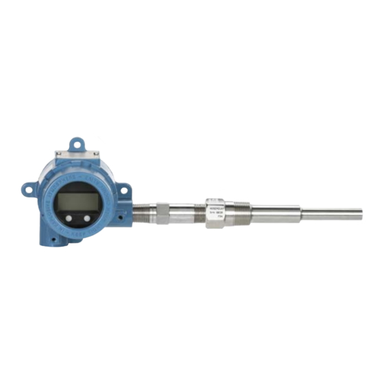
Temperature transmitter
Hide thumbs
Also See for Rosemount 644:
- Reference manual (182 pages) ,
- Quick start manual (52 pages) ,
- Service manual (37 pages)
Table of Contents
Advertisement
Quick Links
Advertisement
Table of Contents

Related Manuals for Emerson Rosemount 644


Summary of Contents for Emerson Rosemount 644
- Page 1 Quick Start Guide 00825-0200-4728, Rev DB February 2015 Rosemount 644 Temperature Transmitter ® with 4-20 mA HART (Revision 5 and 7) Protocol Note Before installing the transmitter, confirm the correct device driver is loaded on the host systems. See page 3...
-
Page 2: Table Of Contents
Quick Start Guide NOTICE This guide provides basic guidelines for Rosemount 644 transmitters. It does not provide instructions for configuration, diagnostics, maintenance, service, troubleshooting, Explosion-proof, Flameproof, or intrinsically safe (I.S.) installations. Refer to the Rosemount 644 Reference Manual (document number 00809-0100-4728) for more instruction. -
Page 3: System Readiness
Rosemount 644 device revisions and files Table 1 provides the information necessary to ensure you have the correct Device Driver files and Documentation for your device. Table 1. Rosemount 644 Device Revisions and Files Software Review Review Identify device... -
Page 4: Transmitter Installation
February 2015 Quick Start Guide Transmitter installation Step 1: Set the alarm switch Set the 644 alarm switch before putting the device into operation. Without an LCD display: 1. Set the loop to manual (if applicable) and disconnect the power. 2. -
Page 5: Verify Configuration
(document number 00809-0200-4728) and Field Communicator Reference Manual for more information. Verify configuration with a Field Communicator A Rosemount 644 DD (device descriptor) must be installed on the Field Communicator to verify the configuration. Fast Key sequences for the latest DD are shown in Table on page 6. - Page 6 February 2015 Quick Start Guide Figure 2. Device Dashboard Field Communicator Interface Table 2. Device Revision 8 and 9 (HART 5 and 7), DD Revision 1 Fast Key Sequence HART 5 HART 7 Function 2, 2, 5, 6 2, 2, 5, 6 Alarm Values 3, 4, 5 3, 4, 5...
- Page 7 Quick Start Guide February 2015 Table 2. Device Revision 8 and 9 (HART 5 and 7), DD Revision 1 Fast Key Sequence HART 5 HART 7 Function 3, 5, 1 3, 5, 1 Loop Test 3, 4, 6, 2 Locate Device 1, 8, 3, 8 Lock Status 2, 2, 5, 5, 3...
- Page 8 February 2015 Quick Start Guide Input or verify Callendar Van-Dusen constants If sensor matching is being used with this combination of a transmitter and sensor, verify the constants input. 1. From the HOME screen, select 2 Configure, 2 Manual Setup, 1 Sensor. 2.
- Page 9 Quick Start Guide February 2015 Figure 4. LOI Menu Switch HART revision mode Not all systems are capable of communicating with HART Revision 7 protocol. This transmitter can be configured for either HART Revision 5 or 7 using a HART capable configuration tool.
-
Page 10: Mount The Transmitter
February 2015 Quick Start Guide Step 3: Mount the transmitter Mount the transmitter at a high point in the conduit run to prevent moisture from draining into the transmitter housing. Head mount transmitter with DIN plate style sensor installation 1. Attach the thermowell to the pipe or process container wall. 2. - Page 11 Quick Start Guide February 2015 Head mount transmitter with threaded sensor installation (2 or 3 conduit entries) 1. Attach the thermowell to the pipe or process container wall. 2. Install and tighten thermowells before applying process pressure. 3. Attach necessary extension nipples and adapters to the thermowell. 4.
- Page 12 February 2015 Quick Start Guide Field mount transmitter with threaded sensor installation 1. Attach the thermowell to the pipe or process container wall. Install and tighten thermowells before applying process pressure. 2. Attach necessary extension nipples and adapters to the thermowell. 3.
-
Page 13: Wire And Apply Power
Quick Start Guide February 2015 Step 4: Wire and apply power Wire the sensor to the transmitter The wiring diagram is located on the device’s top label below the terminal screws 644 Head Mount Transmitter Figure 5. 644 Head Mount - Single and Dual Input Wiring Diagrams *The transmitter must be configured for at least a 3-wire RTD in order to recognize an RTD with a compensation loop. - Page 14 February 2015 Quick Start Guide 644 Field Mount Transmitter Figure 6. 644 Field Mount - Single and Dual Input Wiring Diagrams Power the transmitter An external power supply is required to operate the transmitter. 1. Remove the housing cover (if applicable). 2.
- Page 15 Quick Start Guide February 2015 Load limitation The power required across the transmitter power terminals is 12 to 42.4 Vdc (the power terminals are rated to 42.4 Vdc). To prevent damaging the transmitter, do not allow terminal voltage to drop below 12.0 Vdc when changing the configuration parameters.
- Page 16 February 2015 Quick Start Guide Option 2 1. Connect signal wiring shield to the sensor wiring shield. 2. Ensure the two shields are tied together and electrically isolated from the transmitter housing. 3. Ground shield at the power supply end only. 4.
- Page 17 Quick Start Guide February 2015 Grounded thermocouple inputs Option 1 1. Ground sensor wiring shield at the sensor. 2. Ensure the sensor wiring and signal wiring shields are electrically isolated from the transmitter housing. 3. Do not connect the signal wiring shield to the sensor wiring shield. 4.
-
Page 18: Perform A Loop Test
February 2015 Quick Start Guide Step 5: Perform a loop test The Loop Test command verifies transmitter output, loop integrity, and operation of any recorders or similar devices installed in the loop. Performing a loop test using a Field Communicator Initiate a loop test 1. -
Page 19: Safety Instrumented Systems
Quick Start Guide February 2015 Safety instrumented systems For Safety Certified installations, refer to the Rosemount 644 Reference Manual (document number 00809-0200-4728). The manual is available electronically at www.rosemount.com or by contacting an Emerson Process Management representative. -
Page 20: Product Certifications
February 2015 Quick Start Guide Product Certifications European Directive Information A copy of the EC Declaration of Conformity can be found at the end of the Quick Start Guide. The most recent revision of the EC Declaration of Conformity can be found at www.rosemount.com. - Page 21 Quick Start Guide February 2015 Certificate: 3044581 [Headmount HART] Standards: FM Class 3600: 2011, FM Class 3610: 2010, FM Class 3611: 2004, FM Class 3810: 2005, ANSI/NEMA – 250: 1991; ANSI/IEC 60529: 2004; ANSI/ISA 60079-0: 2009; ANSI/ISA 60079-11: 2009 Markings: [No Enclosure]: IS CL I, DIV I, GP A, B, C, D T4; CL I ZONE 0 AEx ia IIC T4 Ga; NI CL I, DIV 2, GP A, B, C, D T5 [With Enclosure]: IS CL I / II / III, DIV 1, GP A, B, C, D, E, F, G;...
- Page 22 February 2015 Quick Start Guide I1 ATEX Intrinsic Safety Certificate: [Headmount HART]: Baseefa12ATEX0101X [Headmount Fieldbus/PROFIBUS]: Baseefa03ATEX0499X [Railmount HART]: BAS00ATEX1033X Standards: EN 60079-0: 2012, EN 60079-11: 2012 Markings: [HART]: III 1 G Ex ia IIC T6…T4 Ga; [Fieldbus/PROFIBUS]: II 1 G Ex ia IIC T4 Ga; Table 5 for Entity Parameters and Temperature Classifications.
- Page 23 Quick Start Guide February 2015 International E7 IECEx Flameproof Certificate: IECEx FMG 12.0022X Standards: IEC 60079-0:2011, IEC 60079-1:2007-04, IEC 60079-31:2008 Markings: Ex d IIC T6…T1 Gb, T6(-50 °C ≤ T ≤ +40 °C), T5…T1(-50 °C ≤ T ≤ +60 °C); See Table 4 for Process Temperatures.
- Page 24 February 2015 Quick Start Guide NK IECEx Dust Certificate: IECEx FMG 12.0022X Standards: IEC 60079-0: 2011, IEC 60079-31: 2008 Markings: Ex tb IIIC T130 °C Db, (-40 °C ≤ T ≤ +70 °C); IP66; Table 4 for Process Temperatures. Special Conditions for Safe Use (X): 1.
- Page 25 Quick Start Guide February 2015 China E3 China Flameproof Certificate: GYJ111385 Standards: GB3836.1-2000, GB3836.2-2000, GB12476.1-2000 Markings: Ex d IIC T6 Special Conditions of Use (X): 1. Temperature Assembly using temperature sensor type 65, 68, 75, 183, 185 are certified. 2. The ambient temperature range is: Gas/Dust Ambient temperature -40 °C ≤...
- Page 26 February 2015 Quick Start Guide I3 China Intrinsic Safety Certificate: GYJ111384X Standards: GB3836.1-2000, GB3836.4-2000 Markings: Ex ia IIC T4/T5/T6 Special Conditions for Safe Use (X): 1. The ambient temperature range is: When Options do not select Enhance Performance Transmitter output Maximum input power: (W) T code Ambient temperature...
- Page 27 Quick Start Guide February 2015 When Options select Enhanced Performance Terminals of power supply (+, -) Maximum internal Maximum input Maximum Maximum parameters: voltage: input current: input power: (mA) (nF) (mH) ≤ +80 °C) 150 (T ≤ +70 °C) 170 (T 0.67 / 0.8 ≤...
- Page 28 February 2015 Quick Start Guide N3 China Type n Certificate: GYJ101421 Standards: GB3836.1-2000, GB3836.8-2003 Markings: Ex nA nL IIC T5/T6 Special Conditions for Safe Use (X): 1. The relation among T code, ambient temperature range is as following: When Options do not select Enhanced Performance: T code Ambient temperature -40 °C ≤...
- Page 29 Quick Start Guide February 2015 Japan E4 Japan Flameproof Certificate: TC20671 [J2 with LCD], TC20672 [J2], TC20673 [J6 with LCD], TC20674 [J6] Markings: Ex d IIC T5 Combinations K1 Combination of E1, I1, N1, and ND K2 Combination of E2 and I2 K5 Combination of E5 and I5 K7 Combination of E7, I7, and N7 KA Combination of K6, E1, and I1...
- Page 30 February 2015 Quick Start Guide Table 4. Process Temperatures T130 +40 °C +60 °C +60 °C +60 °C +60 °C +60 °C +70 °C Maximum ambient Transmitter with LCD display 0-in. 55 °C 70 °C 95 °C 95 °C 95 °C 95 °C 95 °C 3-in.
- Page 31 Quick Start Guide February 2015 Figure 8. EC Declaration of Conformity for 644 Temperature Transmitter...
- Page 32 February 2015 Quick Start Guide...
- Page 33 Quick Start Guide February 2015...
- Page 34 February 2015 Quick Start Guide...
- Page 35 Quick Start Guide February 2015...
- Page 36 Standard Terms and Conditions of Sale can be found at: www.rosemount.com\terms_of_sale. Middle East and Africa Regional Office AMS and the Emerson logo are registered trademarks and service marks of Emerson Electric Co. Emerson Process Management Rosemount and Rosemount logotype are registered trademarks of Emerson FZE P.O.