Table of Contents
Advertisement
Quick Links
Table of Contents
Cover – Title Sheet
Instructor Resume
Coarse Objectives
Training Outline
Operation and Maintenance Training for Vulcan Industries EWP Washing Press
Section 1 - Safety
Section 2 – Operations
Section 3 – Electrical Sequence of Operation
Section 4 – Maintenance
All training will consist of both Classroom and hands-on training.
Twelve (12) sets of this outline will be provided for training purposes
No additional audio/visual training aids are required for this training.
Advertisement
Table of Contents

Related Manuals for Vulcan-Hart EWP 250-1200

Summary of Contents for Vulcan-Hart EWP 250-1200
- Page 1 Table of Contents Cover – Title Sheet Instructor Resume Coarse Objectives Training Outline Operation and Maintenance Training for Vulcan Industries EWP Washing Press Section 1 - Safety Section 2 – Operations Section 3 – Electrical Sequence of Operation Section 4 – Maintenance All training will consist of both Classroom and hands-on training.
-
Page 2: Training Manual
Project: Beaver Channel Pump Station and Related Modifications and Contract C- New WWTP Project Location: Clinton, IA Equipment: 1 – Screening Washing Press Model EWP 250-1200 Equipment Tag No.: 10SCS-WSP01 Contract Specification Section: 11092 Related Equipment: 1 - Mensch Crawler Screen Model No. FT48 CI “Severe Duty”... - Page 3 VULCAN INDUSTRIES, INC. Submittal Documents for: Clinton WWTP Clinton, IA Vulcan Ind. Job No.: 10010 Contractor: Gridor Construction 11092 Specification Section References: SERVICE TECHNICIAN RESUMES Vulcan Industries, Inc. 212 S. Kirlin St., Missouri Valley, IA. 51555 Email: www.Vulcanindustries.com Phone 712.642.2755 • Fax 712.642.4256...
- Page 4 VULCAN INDUSTRIES, INC. WATER / WASTEWATER TREATMENT EQUIPMENT 212 S. KIRLIN ST. MISSOURI VALLEY, IA. 51555 (712) 642-2755 or fax (712) 642-4256 Email www.vulcanindustries.com SERVICE REPRESENTATIVE QUALIFICATIONS Carlton Griffin Mr. Griffin has been employed full time by Vulcan Industries for fifteen years as a service representative.
- Page 5 Kenny assisted other service representatives on several service and training operations before becoming a full time serviceman. Prior to being employed by Vulcan, Kenny worked for many years as a technician in the HVAC and electrical industry. He has extensive knowledge in the areas of electrical, electronics, mechanical and pneumatic equipment.
- Page 6 Coarse Objectives Vulcan Model EWP Washing Press Identify, describe and/or perform the following: 1. Safety Hazards 2. Functional Description of Equipment 3. Technical Description and Component Identification 4. Equipment Operation 5. Troubleshooting 6. Maintenance and Lubrication 7. Maintenance Demonstration The intent of this training is to provide all plant personnel (Operations, Maintenance and Electrical) with the general knowledge to operate and maintain the equipment.
- Page 7 c. Electrical equipment device functions 4. Maintenance a. Lubrication schedule b. Daily maintenance schedule c. Weekly maintenance schedule d. Monthly maintenance schedule e. Half-yearly maintenance schedule f. Maintenance and repair of individual components...
-
Page 8: Section 1 General Safety Instructions
Section 1 General Safety Instructions General Safety Instructions Operator’s Responsibilities This machine was designed and built to operate within all applicable safety guidelines. In practice, however, this safety can only be achieved if all the necessary measures are taken. It is the responsibility of the owner and/or operator to ensure that these measures are taken and to monitor their performance. - Page 9 Section 1 General Safety Instructions C. Before Turning the Machine on Familiarize yourself with: The operating and control elements of the machine. Machine equipment. The mode of operation of the machine. The immediate surroundings of the machine. ...
- Page 10 Section 1 General Safety Instructions Ensure that all tools, materials and other equipment used have been removed from the work area. Clean the work area and remove liquids that might have spilled. Ensure that all safety devices of the machine are functioning properly. F.
- Page 11 Section 1 General Safety Instructions These personnel must be familiar with the operating instructions. In addition, the following qualifications are needed for the following activities: Only electricians may perform work on electrical equipment. Only trained personnel may perform maintenance, upkeep and repair work. Other Dangers A.
- Page 12 Section 1 General Safety Instructions Safety Symbols The following are pictures and an explanation of all the safety stickers that are used on Vulcan equipment. Some of these may or may not pertain to your particular machine. A spreader bar must be used when lifting this machine.
- Page 13 Section 1 General Safety Instructions Grease point for maintenance reference. Grease point for maintenance reference. Watch for an open pit. Equipment in Automatic mode may start if sensors are triggered. Make sure the machine is properly locked-...
- Page 14 Section 1 General Safety Instructions Do not operate the machine with covers removed. Take care in not getting caught in the exposed screw or other moving parts.
-
Page 15: Functional Description
Section 2 Operating 2.1. Functional Description Valve Operations 1. Injects washwater into the 3. Introduces washwater into washing zone through the top of the washing zone. hollow shaft spiral. 2. Sprays water over 4. Flushes dewatering zone and screenings as they enter drain pan. -
Page 16: Technical Description
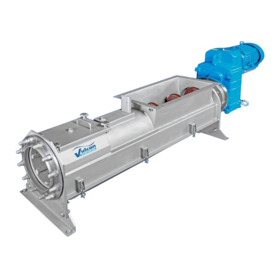
Section 2 Operating The cleaned material can be conveyed directly to a container through the discharge pipe. 2.2 Technical Description The wash press is designed as a spiral press to wash organic dissolvable materials out of coarse and fine screened material. The spiral press then dewaters, compresses and transports the material. -
Page 17: Operating Procedure
Section 2 Operating A gear motor drives the spiral. The drive shaft to the spiral passes through a sealed thrust bearing box, which takes all of the thrust from the pressing operation, and prevents pressed liquid from entering the gear box. 2.3 Operating Procedure 2.3.1 Normal Operation A. - Page 18 Section 2 Operating For long periods of shut-down, the discharge pipe should be purged of screenings, which could harden in the pipe and cause a blockage when the equipment is re- started. The pipe can be purged by running ice through the press until all the screenings are purged.
-
Page 19: Section 3 Electrical Functions
Section 3 Electrical Functions Sequence of Operation 1. After the Washing Press has been properly installed/adjusted, motor rotation checked and all control panel devices (timer(s), overload(s), current sensing relay, etc.) have been set, automatic operation may proceed. Make sure all personnel are clear of the equipment. - Page 20 Section 3 Electrical Functions Shaft/Valve Sequencing Batch Mode Step 1. Screw forward, valves 1 & 2 (hollow shaft & hopper) energized. (xx seconds) Step 2. Screw stopped, valves 1 & 3 (hollow shaft & washing zone) energized. (xx seconds)** Step 3. Screw reverse, valves 1 & 3 (hollow shaft & washing zone) energized. (xx seconds) Step 4.
- Page 21 Section 3 Electrical Functions Device Functions Disconnect The disconnect removes high voltage from the circuit breakers and transformer. Voltage is still present at the top of the disconnect. When the disconnect switch is in the "Off" position, the control panel will not function. This will not remove voltage supplied from other external sources.
- Page 22 Section 3 Electrical Functions Solid State MOL This device provides phase loss and short circuit protection. It should be adjusted to the full load amp rating of the motor that the starter is controlling. Pressing the reset button located on the solid-state motor overload will reset the unit. Automatic Control Devices Wash Cycle Counter The wash cycle counter programmed within the PLC will...
-
Page 23: Section 4 Maintenance
Section 4 Maintenance Machine Maintenance Safety Precautions (Refer to Section 1 for additional Safety information) Vulcan industries will not be responsible for any harm or injury that may result from the improper operation of this equipment. Furthermore, Vulcan Industries will not guarantee this equipment if improperly operated or operated without the designed safety features. - Page 24 Section 4 Maintenance Note: If there is a significant amount of fat, oil or grease in the screenings, more frequent cleaning may be necessary. Dirty screenings are an indication of a plugged de-watering head. Remove or open de- watering head cover Dewatering Head Cover and drain pan Clean dewatering head...
- Page 25 Section 4 Maintenance Grease Zerk Fig. 4.2.C D. Semi-annually or every 600 operating hours Checking fasteners Perform the following maintenance items: Check all fasteners for a secure fit. Check all electrical connections for cleanliness and secure fits. Secure and tighten any loose connections. ...
- Page 26 Section 4 Maintenance Vent Fig. 4.2.D Drain Plug Level Plug...
- Page 27 Section 4 Maintenance Maintenance /Lubrication Schedule Occurance Inspection Activity Daily Entire Machine Check operability, leaks Check motor temprature Motor & Reducer Check for sufficient water and air Water Supply supply pressures Records Record run time hours Weekly (30 hrs) Entire Machine Clean the outside De-watering Sieve Flush...
- Page 28 Section 4 Maintenance Required Tools The following is a categorized list of tools to have available when working on this machinery. Hand Tools: Standard maintenance tools (i.e. screwdrivers, allen wrenches, socket, open-end and box-end wrenches up to 1-1/2” and if possible, metric up to 32mm, punches, etc.) 18”...
- Page 29 Section 4 Maintenance Replacing the Swivel Joint A. Replacing the Swivel Joint See Figure 4.6 above for descriptions. The following must be observed before removing swivel joint: Refer to Section 1: General Safety Instructions, for necessary safety procedures. Remember, the equipment is controlled automatically, and may start at any time. Follow your local “Lock Out –...
- Page 30 Section 4 Maintenance Removing and Installing the Spiral, Drive Motor and Bearing Unit Fig. 4.7 A. Removing the Spiral, Drive Gear and Bearing Unit See Figure 4.7 above for descriptions. The following must be observed before removing the spiral of the wash press: ...
- Page 31 Section 4 Maintenance Remove all wash water connections to the spiral (2). Remove all nuts (4) from studs between the bearing unit (3) and the frame (5) and remove the spiral along with the bearing unit out of the frame. Remove the bearing unit from the spiral shaft.
- Page 32 Section 4 Maintenance (10) Fig. 4.7.B See Figure 4.7.B for descriptions. If the spiral does not run freely, the axial alignment of the spiral has to be corrected. Loosen the bolts (7) and make changes to the alignment by adjusting the screws (10). Tighten the bolts (7) after final adjustment. The bearing housing should now be lubricated using a manual grease gun.
- Page 33 Section 4 Maintenance Clamp Block & Connection Screw Fig. 4.8 To change the brush, the spiral must first be removed from the frame. Follow the steps 4.7.A to remove the spiral; then proceed: Loosen connection screws at the clamp blocks. Remove the old brush.
- Page 34 Section 4 Maintenance...
- Page 35 Section 4 Maintenance 4.10 Recommended Spare Parts Recommended Wash Press Spare Parts Project: Vulcan Job #: Machine Desc.: Vulcan Wash Press Machine #: Quantity Description Solenoid Valve Replacement Brush for Screw 1 Set Shaft Seals & Bearings (thrust bearing unit)