Table of Contents
Advertisement
Quick Links
Advertisement
Chapters
Table of Contents

Summary of Contents for Toyota IPUP T100L
- Page 1 IPUP T100L, EC100L Instruction Manual Date: 2006/12 IPUP T100L V3.4 EC100L V2.1...
- Page 2 IPUP T100L / EC100L Instruction Manual Dear Customers: Thank you for purchasing IPUP T100L / EC100L dry vacuum pumps manufactured by TOYOTA INDUSTRIES CORPORATION. Please read through this manual for ensuring correct operation and handling and for ensuring a long service life.
- Page 3 IPUP T100L / EC100L Instruction Manual INDEX Page 1. INTRODUCTION 1-1. Scope 1-2. Description 1-3. Technical Data 1-3-1. Technical data table 1-3-2. Technical data drawing 1-4. CE marking certificate 1-5. SEMI S2 certificate 2. SAFETY 2-1. General 2-2. Identified label symbols 2-3.
- Page 4 IPUP T100L / EC100L Instruction Manual INDEX Page 3. INSTALLATION 3-1. General 3-2. Unpacking Precaution 3-3. Moving procedure 3-3-1. Hoisting the pump to move 3-3-2. Moving the pump 3-4. Installation Procedure 3-4-1. Installation precaution 3-4-2. Pump positioning method 3-4-3. Method of fixation 3-4-4.
- Page 5 IPUP T100L / EC100L Instruction Manual INDEX Page 4. OPERATION 4-1. Indication 4-2. Main Switch 4-3. Operation Method 4-4. Control by SPI 4-4-1. SPI connection 4-4-2. Adjustment before operation 4-4-3. Pump running with SPI 4-5. Control by Hand-held controller 4-5-1.
- Page 6 IPUP T100L / EC100L Instruction Manual INDEX Page 5. TROUBLESHOOTING 5-1 Pump does not start 5-2 Error message 5-3 Pump is running and no error messages are indicated 6. MAINTENANCE 6-1 General 6-2 Overhaul Maintenance Intervals 6-3 Pump Removal & Return Procedure...
-
Page 7: Table Of Contents
IPUP T100L / EC100L Instruction Manual 1. INTRODUCTION Page 1-1. Scope 1-2. Description 1-3. Technical Data 1-3-1. Technical data table 1-3-2. Technical data drawing 1-4. CE marking certificate 1-5. SEMI S2 certificate http://www.toyota-industries.com/ TOYOTA INDUSTRIES CORPORATION... -
Page 8: Scope
IPUP T100L / EC100L Instruction Manual 1. INTRODUCTION 1-1. Scope This manual covers the IPUP T100L, EC100L dry vacuum pump for semiconductor equipment. These pumps are suitable for loadlock, transfer chamber and all other clean process. SPI connector... -
Page 9: Description
1. INTRODUCTION 1-2. Description The IPUP T100L / EC100L is a roots type vacuum pump that rotates a pair of synchronized, timing gears. The pump is driven by a 3-phase induction motor. Bearings and gears on the high pressure side are lubricated by fluoric type oil. Nitrogen is not required for shaft seals. -
Page 10: Technical Data
IPUP T100L / EC100L Instruction Manual 1. INTRODUCTION 1-3. Technical Data 1-3-1. Technical data table Item Unit IPUP T100L EC100L Dimensions Dimensions and 590×300×280 590×300×280 (LxHxW) weight Weight Maximum revolution r/min 5250 4650 (Default rpm setting) m3/h Peak pumping speed... -
Page 11: Technical Data Drawing
IPUP T100L / EC100L Instruction Manual 1. INTRODUCTION 1-3. Technical Data 1-3-2. Technical Data drawing IPUP T100L Dimension Diagram Unit: mm 45.4 21.8 http://www.toyota-industries.com/ TOYOTA INDUSTRIES CORPORATION... - Page 12 IPUP T100L / EC100L Instruction Manual 1. INTRODUCTION 1-3. Technical Data 1-3-2. Technical Data drawing (continued) Position of IPUP T100L center of gravity Unit: mm Pump Position of pump center of gravity weight (kg) L (mm) W (mm) H (mm)
- Page 13 IPUP T100L / EC100L Instruction Manual 1. INTRODUCTION 1-3. Technical Data 1-3-2. Technical Data drawing (continued) Dimensions for two horizontally installed IPUP T100L pumps Unit: mm 21.8 45.4 Positions of stacking brackets Bottom Top View http://www.toyota-industries.com/ TOYOTA INDUSTRIES CORPORATION...
- Page 14 IPUP T100L / EC100L Instruction Manual 1. INTRODUCTION 1-3. Technical Data 1-3-2. Technical Data drawing (continued) Position of center of gravity for two horizontally installed IPUP T100L pumps Unit: mm Pump Position of pump center of gravity weight (kg)
-
Page 15: Ce Marking Certificate
IPUP T100L / EC100L Instruction Manual 1. INTRODUCTION 1-4. CE marking certificate http://www.toyota-industries.com/ TOYOTA INDUSTRIES CORPORATION... -
Page 16: Semi S2 Certificate
IPUP T100L / EC100L Instruction Manual 1. INTRODUCTION 1-5. SEMI S2 certificate http://www.toyota-industries.com/ TOYOTA INDUSTRIES CORPORATION... - Page 17 IPUP T100L / EC100L Instruction Manual 2. SAFETY PRECAUTION Page 2-1. General 2-2. Identified label symbols 2-3. Safety Instruction 2-3-1. Power supply 2-3-2. EMO system 2-3-3. Safety sensors 2-4. Safety Precaution http://www.toyota-industries.com/ TOYOTA INDUSTRIES CORPORATION...
- Page 18 2. SAFETY PRECAUTION 2-1. General A dangerous voltage for the human body is used inside the IPUP T100L / EC100L. Improper operation may possibly result in a serious accident. Thoroughly read this manual to prevent accidents before using the product.
- Page 19 2-3. Safety Instruction 2-3-1. Power supply IPUP T100L / EC100L are not provided with a 10000 AIC main circuit breaker. Supply power to the pump from process tool with a 15 A max main circuit breaker. (in US UL489, in Europe EN60947-2 approval) Do not place pump where power-disconnecting devices become difficult to access.
- Page 20 The performance and safety of this product are guaranteed only when the pump is operated within the parameter ranges specified herein. The IPUP T100L / EC100L is designed for loadlock, transfer chamber and all other clean chambers. Never use the...
- Page 21 T100L does not need daily maintenance and daily cleaning. Never open the side panel to prevent electric shock or burn WARNING injury. Never move the IPUP T100L / EC100L while the pump is running. WARNING When operation is needed soon after stopping the pump,...
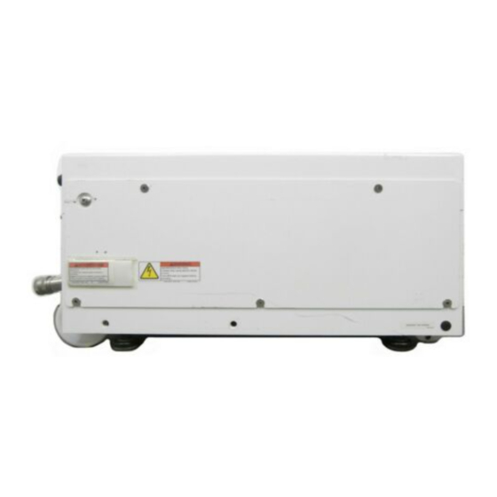
- Page 22 IPUP T100L / EC100L Instruction Manual 2. SAFETY PRECAUTION 2-4. Safety Precaution (continued) The following warning labels are attached to the IPUP T100L / EC100L This is located on the side of the pump and indicates that an electric shock may occur if you touch live internal parts.
- Page 23 IPUP T100L / EC100L Instruction Manual 3. INSTALLATION Page 3-1. General 3-2. Unpacking Precaution 3-3. Moving Procedure 3-3-1. Hoisting the pump to move 3-3-2. Using the optional handle to move 3-4. Installation Procedure 3-4-1. Installation precaution 3-4-2. Pump positioning method 3-4-3.
-
Page 24: General
IPUP T100L / EC100L Instruction Manual 3. INSTALLATION 3-1. General Only qualified, well-trained personnel can install this product. When unpacking, confirm that the all parts listed in attached option list are included. 3-2. Unpacking Precaution When packed, the product weighs about 130kg. -
Page 25: Moving Procedure
IPUP T100L / EC100L Instruction Manual 3. INSTALLATION 3-3. Moving procedure 3-3-1. Hoisting the pump to move The pump itself weighs about 104kg. Use a hoist or other appropriate device when lifting it up. Using the L-shape brackets screwed to the upper surface of the enclosure, hoist the pump as follows: 1. - Page 26 IPUP T100L / EC100L Instruction Manual 3. INSTALLATION 3-3. Moving procedure (continued) 3-3-2. Moving the pump Use appropriate cart or moving equipment to move the pump. Make sure that all four adjusters on the pump are DOWN to prevent any sliding of the pump on the cart or moving equipment.
-
Page 27: Using The Optional Handle To Move
IPUP T100L / EC100L Instruction Manual 3. INSTALLATION 3-3. Moving procedure (continued) 3-3-2. Using the optional handle to move (continued) Pay attention so as not to trap your hands between the optional handle and cover when using or stowing the optional handle. -
Page 28: Installation Procedure
IPUP T100L / EC100L Instruction Manual 3. INSTALLATION 3-4. Installation Procedure 3-4-1. Installation precaution Install the pump horizontally. Before starting operation, pump inclination angle must be adjusted to be within angles WARNING of 2 degrees with horizontal. It cannot be operated at any angle or vertically. -
Page 29: Pump Positioning Method
IPUP T100L / EC100L Instruction Manual 3. INSTALLATION 3-4. Installation Procedure (continued) 3-4-2. Pump positioning method Four adjusters are provided on the bottom of pump. Carry out positioning by observing the following instructions: 1. Turn the adjusters clockwise to lower them using an M10 spanner or the like. -
Page 30: Method Of Fixation
IPUP T100L / EC100L Instruction Manual 3. INSTALLATION 3-4. Installation Procedure (continued) 3-4-3. Method of fixation ・In case of fixing the pump to the equipment Fix the pump to the equipment using the bracket as shown in following figure. Screw hole for fixing. -
Page 31: When Using Two Vertically Stacked Pumps
3-4. Installation Procedure (continued) 3-4-4. When using two vertically stacked pumps. It is possible to operate two vertically stacked IPUP T100L / EC100L pumps. Observe the following instructions for stacking two pumps vertically. 1. Check that all three stacking brackets are fixed on the enclosure. -
Page 32: Connection To The Pumping Circuit
IPUP T100L / EC100L Instruction Manual 3. INSTALLATION 3-5. Connection to the pumping circuit Specifications for the vacuum pump inlet and outlet are as listed below; · Inlet flange: NW50 · Exhaust flange: NW25 Inlet flange Exhaust flange Connect the inlet flange to your vacuum line and the exhaust flange to your exhaust line with appropriate vacuum parts. -
Page 33: Electrical Connection
Max. power capacity 4.6 kVA AWG14/4 Cable outside diameter UL Style 2587/2501 Conductor diameter 2.08 mm and over Conductor material Copper IPUP T100L will automatically restart to avoid system down when 1 second power loss occurs. http://www.toyota-industries.com/ TOYOTA INDUSTRIES CORPORATION... -
Page 34: Electrical Connection Method
IPUP T100L / EC100L Instruction Manual 3. INSTALLATION 3-6. Electrical connection (Continued) 3-6-3. Electrical connection method · The main power supply connector is located as shown below. Straight type female connector M4 screw (2 places) Connector cover · Observe the following instructions when connecting the main power supply connector: 1. -
Page 35: Signal
3-7. Signal 3-7-1. Outline The IPUP T100L / EC100L is designed as a built-in pump of the APPLIED MATERIALS equipment and controlled through the APPLIED MATERIALS SPI. The pump is able to be operated by an equipment through SPI interface as well as monitoring pump status. -
Page 36: Spi Pin Assignmment
IPUP T100L / EC100L Instruction Manual 3. INSTALLATION 3-7. Signal (continued) 3-7-3. SPI Pin assignmment Function Signal Dry contact state /OUT · Pin 2 DC0V: Pump Off Pump ON/OFF · Pin 2 DC24V Pump On Signal · Contact Closed: Pump On... -
Page 37: External Output For Monitoring System
IPUP T100L / EC100L Instruction Manual 3. INSTALLATION 3-7. Signal (continued) 3-7-3. SPI Pin assignmment (continued) Pump Starting/Stopping Load Pump Running Circuit protector DC24V(option) Load Warning Load Hazard Load DC24V Load Final valve interlock DC24V Rotation speed control DC 0V-10V 3-7-4. -
Page 38: Cooling Water
3. INSTALLATION 3-8. Cooling water 3-8-1. Specification of cooling water Use cooling water with the following characteristics in order to prevent clogging and corrosion of the IPUP T100L / EC100L cooling system. Non-corrosive industrial water or Type treated soft water Flow rate 1.5L/min or more... -
Page 39: Connection Of Cooling Water
IPUP T100L / EC100L Instruction Manual 3. INSTALLATION 3-8. Cooling water(continued) 3-8-2. Connection of cooling water Cooling water connectors are located as shown below. Cooling water IN Cooling water OUT Part Maker Part number Cooling water IN Parker... -
Page 40: Operation Condition Setting
IPUP T100L / EC100L Instruction Manual 3. INSTALLATION 3-9. Operation condition setting Set the operation condition of the pump for your process before using the pump. In case of using in improper condition, performance and safety are not guaranteed. In such cases, we will not be responsible for any failures. -
Page 41: Pump Storage
IPUP T100L / EC100L Instruction Manual 3. INSTALLATION 3-9. Operation condition setting (Continued) 3-9-2. Setting items (continued) Communication method Communication method of external monitoring output can be changed from RS232C to RS485. This is used on Dry Pump Monitoring System (option). When this option is not used, do not change initial setting. - Page 42 IPUP T100L / EC100L Instruction Manual 4. OPERATION Page 4-1. Indication 4-2. Main Switch 4-3. Operation Method 4-4. Control by SPI 4-4-1. SPI connection 4-4-2. Adjustment before operation 4-4-3. Pump running with SPI 4-5. Control by Hand-held controller 4-5-1. Hand-held controller connection 4-5-2.
-
Page 43: Indication
IPUP T100L / EC100L Instruction Manual 4. OPERATION 4-1. Indication On the front panel there are indicator LEDs that display the pump operating status. The indicator LEDs light up or go off according to the pump operating status when the pump main switch is ON. -
Page 44: Main Switch
IPUP T100L / EC100L Instruction Manual 4. OPERATION 4-2. Main Switch Power ON The main power switch is located on the front panel as shown below. ·Turning this switch on (by pressing the 1 mark side) turns the green indicator LED light up. -
Page 45: Operation Method
IPUP T100L / EC100L Instruction Manual 4. OPERATION 4-3. Operation Method The pump has the following operation modes: · Remote mode using the SPI of APPLIED MATERIALS. · Local mode using the hand-held controller. The following actions are possible in the remote mode using SPI: ·... -
Page 46: Control By Spi
IPUP T100L / EC100L Instruction Manual 4. OPERATION 4-4. Control by SPI 4-4-1. SPI connection The SPI connector is located on the rear panel of the pump. Connect and fix the SPI cable of the equipment to the SPI connector. -
Page 47: Control By Hand-Held Controller
IPUP T100L / EC100L Instruction Manual 4. OPERATION 4-5. Control by Hand-held controller 4-5-1. Hand-held controller connection Connect the connector of the hand-held controller provided to the connector identified as KEYBOARD on the front panel of the pump. 4-5-2. Key functions... -
Page 48: Display Menu
IPUP T100L / EC100L Instruction Manual 4. OPERATION 4-5. Control by Hand-held controller(Continued) 4-5-4. Display Menu TOYOTA INDUSTRIES CORPORATION http://www.toyota-industries.com/... -
Page 49: Changing Operation Modes
IPUP T100L / EC100L Instruction Manual 4. OPERATION 4-6. Changing Operation Modes Upon power ON, the pump is set to LOCAL mode. 4-6-1. Changing from local to remote mode Method 1: Apply 24-VDC voltage between pins 1 and 2 of APPLIED MATERIALS SPI, which automatically causes transition to the remote mode. -
Page 50: Setting
IPUP T100L / EC100L Instruction Manual 4. OPERATION 4-7. Setting 4-7-1. Alarm Log ·Check the alarm log to investigate the root cause of the alarm when the alarm is generated. How to check Operation step Key to be used Indication... -
Page 51: Updating Clock
IPUP T100L / EC100L Instruction Manual 4. OPERATION 4-7. Setting (continued) 4-7-2. Updating Clock It is necessary to adjust the pump clock to your local date and time to ensure correct maintenance schedule and alarm log before beginning operation. Date and Time changing method:... -
Page 52: Remote/Local Mode Setting
IPUP T100L / EC100L Instruction Manual 4. OPERATION 4-7. Setting (continued) 4-7-3. REMOTE/LOCAL mode ·Use the hand-held controller to change mode. Operation step Key to be used Indication Go to Detail Menu (refer to 4-5-4) Detail Menu Go to Setting Menu... -
Page 53: Operation Condition Setting
Rev Speed Set? DOWN keys. 5150rpm Press SET key to Rev Speed Set? complete change. 5150rpm Setting range for IPUP T100L is from 1000rpm to 5250rpm. Setting range for EC100L is from 1000rpm to 4650rpm. TOYOTA INDUSTRIES CORPORATION http://www.toyota-industries.com/... - Page 54 IPUP T100L / EC100L Instruction Manual 4. OPERATION 4-7. Setting (continued) 4-7-4. Operation condition (continued) 4-7-4-2. Maintenance Warning Time The maintenance warning time can be changed using the hand-held controller Operation step Key to be used Indication Go to Detail Menu...
-
Page 55: Other Function Setting
IPUP T100L / EC100L Instruction Manual 4. OPERATION 4-7. Setting (continued) 4-7-5. Other function 4-7-5-1. Buzzer The buzzer can be turned On or OFF, when alarm (warning or hazard) occurs. Operation step Key to be used Indication Go to Detail Menu... - Page 56 IPUP T100L / EC100L Instruction Manual 4. OPERATION 4-7. Setting (continued) 4-7-5. Other function(continued) 4-7-5-2. Temperature indication unit setting Temperature unit shown on Hand-held controller can be changed. Operation step Key to be used Indication Go to Detail Menu (refer to 4-5-4)
- Page 57 IPUP T100L / EC100L Instruction Manual 4. OPERATION 4-7. Setting (continued) 4-7-5. Other function (continued) 4-7-5-3. Communication method Communication method of external monitoring output can be changed from RS232C to RS485. Operation step Key to be used Indication Go to Detail Menu...
- Page 58 IPUP T100L / EC100L Instruction Manual 4. OPERATION 4-7. Setting (continued) 4-7-5 . Other function (continued) 4-7-5-4. Monitoring ID Operation step Key to be used Indication Go to Detail Menu (refer to 4-5-4) Detail Menu Go to Setting Menu (refer to 4-5-4)
- Page 59 IPUP T100L / EC100L Instruction Manual 4. OPERATION 4-7. Setting (continued) 4-7-5. Other function (continued) 4-7-5-5. Integral Power Consumption Electrical energy consumption can be displayed during any period. I n t e g r a l P o w e r X X X X X .
- Page 60 IPUP T100L / EC100L Instruction Manual 4. OPERATION 4-7. Setting (continued) 4-7-5. . Other function (continued) 4-7-5-6. Setting reset Operation step Key to be used Indication Go to Detail Menu (refer to 4-5-4) Detail Menu Go to Setting Menu (refer to 4-5-4)
- Page 61 IPUP T100L / EC100L Instruction Manual 5. TROUBLESHOOTING Page 5-1. Pump does not start. 5-2. Error messages 5-3. Pump is running and no error messages are indicated. TOYOTA INDUSTRIES CORPORATION http://www.toyota-industries.com/...
- Page 62 IPUP T100L / EC100L Instruction Manual 5. TROUBLESHOOTING 5-1. Pump does not start. When turning on after turning off, wait 30 seconds so that the electricity of the DC capacitor in the converter can be discharged. Otherwise, the pump cannot start due to converter error (FC Alarm). ...
- Page 63 IPUP T100L / EC100L Instruction Manual 5. TROUBLESHOOTING 5-2. Error message Error Message Error Description Troubleshooting Warning Hazard - Check if air is not rushing in. (Leaking, Actual motor speed stays lower than ○ ○ PumpOverLoad Broken valve, e.t.c.) setting speed for certain time.
- Page 64 IPUP T100L / EC100L Instruction Manual 5. TROUBLESHOOTING 5-2. Error message (continued) Error Message Error Description Troubleshooting Warning Hazard - Contact your service representative for repair. ○ - 51 MainteTime Total run hour exceeds setting. - Change the maintenance warning time setting if you would like to continue running the pump.
- Page 65 IPUP T100L / EC100L Instruction Manual 5. TROUBLESHOOTING 5-3. Pump is running and no error messages are indicated. Problem Possible Root Cause Warning Hazard Troubleshooting - Check foreline leakage. - - Plumbing Problem - Check if exhaust is not clogged.
- Page 66 IPUP T100L / EC100L Instruction Manual 6. MAINTENANCE Page 6-1 General 6-2 Overhaul Maintenance Intervals 6-3 Pump Removal & Return Procedure 6-4 Pump Disposal 6-5 Application Form for Pump Return http: //www.toyota-industries.com/ TOYOTA INDUSTRIES CORPORATION ...
-
Page 67: General
IPUP T100L / EC100L Instruction Manual 6. MAINTENANCE 6-1 General The IPUP T100L / EC100L do not need daily maintenance or daily cleaning. 6-2 Overhaul Maintenance Intervals · Overhaul Maintenance Time default setting is 18000 hours. When the maintenance time has expired, the system automatically notifies the operator of the WARNING information. -
Page 68: Pump Removal & Return Procedure
IPUP T100L / EC100L Instruction Manual 6. MAINTENANCE 6-3 Pump Removal & Return Procedure Follow the Pump Removal & Return Procedure and take notice of appropriate precautions, when you need to remove and return the pump. If you do not, you can cause injury to people and damage to ... -
Page 69: Pump Disposal
IPUP T100L / EC100L Instruction Manual 6. MAINTENANCE 6-3 Pump Removal & Return Procedure (Continued) 1. Only qualified, well-trained personnel can perform pump removal. Check the process gases which the pump has been exposed to. Use personal safety protective equipment as instructed in your company safety guideline. -
Page 70: Application Form For Pump Return
IPUP T100L / EC100L Instruction Manual 6. MAINTENANCE 6-5 Application Form for Pump Return Customer Process Information Co. name: Process: Division: Date of failure: Name.: Tel No.: FAX No: Title: Pump Information Model Name Serial No.: Reason: Chemical Information Notice: ¨Corrosive... - Page 71 IPUP T100L / EC100L Instruction Manual 7. APPENDIX Page 7-1. Electrical Circuit Diagram 7-2. Cooling Diagram 7-3. Material Safety Data Sheet 7-3-1. Lubricant http://www.toyota-industries.com/ TOYOTA INDUSTRIES CORPORATION...
-
Page 72: Electrical Circuit Diagram
IPUP T100L / EC100L Instruction Manual 7. APPENDIX 7-1. Electrical Circuit Diagram http://www.toyota-industries.com/ TOYOTA INDUSTRIES CORPORATION... -
Page 73: Cooling Diagram
IPUP T100L / EC100L Instruction Manual 7. APPENDIX 7-2. Cooling Diagram Cooling Path Electronic circuit Water In 6 3 Pump 1 Motor 2 7.Converter Water Out 5 Tc Temperature sensor M Motor temperature sensor Cooling plate (4 places)... -
Page 74: Material Safety Data Sheet
IPUP T100L / EC100L Instruction Manual 7. APPENDIX 7-3. Material Safety Data Sheet 7-3-1. Lubricant http://www.toyota-industries.com/ TOYOTA INDUSTRIES CORPORATION... - Page 75 IPUP T100L / EC100L Instruction Manual 7. APPENDIX 7-3. Material Safety Data Sheet(continued) 7-3-1. Lubricant (continued) http://www.toyota-industries.com/ TOYOTA INDUSTRIES CORPORATION...
- Page 76 IPUP T100L / EC100L Instruction Manual 7. APPENDIX 7-3. Material Safety Data Sheet(continued) 7-3-1. Lubricant (continued) http://www.toyota-industries.com/ TOYOTA INDUSTRIES CORPORATION...
- Page 77 IPUP T100L / EC100L Instruction Manual 7. APPENDIX 7-3. Material Safety Data Sheet(continued) 7-3-1. Lubricant (continued) http://www.toyota-industries.com/ TOYOTA INDUSTRIES CORPORATION...
- Page 78 IPUP T100L / EC100L Instruction Manual 7. APPENDIX 7-3. Material Safety Data Sheet(continued) 7-3-1. Lubricant (continued) http://www.toyota-industries.com/ TOYOTA INDUSTRIES CORPORATION...
- Page 79 IPUP T100L / EC100L Instruction Manual 7. APPENDIX 7-3. Material Safety Data Sheet(continued) 7-3-1. Lubricant (continued) http://www.toyota-industries.com/ TOYOTA INDUSTRIES CORPORATION...
- Page 80 IPUP T100L / EC100L Instruction Manual 7. APPENDIX 7-3. Material Safety Data Sheet(continued) 7-3-1. Lubricant (continued) http://www.toyota-industries.com/ TOYOTA INDUSTRIES CORPORATION...
- Page 81 IPUP T100L / EC100L Instruction Manual 7. APPENDIX 7-3. Material Safety Data Sheet(continued) 7-3-1. Lubricant (continued) http://www.toyota-industries.com/ TOYOTA INDUSTRIES CORPORATION...
- Page 82 IPUP T100L / EC100L Instruction Manual 7. APPENDIX 7-3. Material Safety Data Sheet(continued) 7-3-1. Lubricant (continued) http://www.toyota-industries.com/ TOYOTA INDUSTRIES CORPORATION...
- Page 83 IPUP T100L / EC100L Instruction Manual 8. EC100L V2.1 APPENDIX 8-1. Scope This appendix covers the EC100L V2.1 dry vacuum pump for semiconductor equipment. EC100L is suitable for loadlock, transfer chamber and all other clean process. Power switch ...
- Page 84 IPUP T100L / EC100L Instruction Manual 8. EC100L V2.1 APPENDIX 8-2. Technical Data 8-2-1. Technical Data drawing EC100L Dimension Diagram Unit: mm 45.4 21.8 http://www.toyota-industries.com/ TOYOTA INDUSTRIES CORPORATION...
- Page 85 IPUP T100L / EC100L Instruction Manual 8. EC100L V2.1 APPENDIX 8-2. Technical Data 8-2-1. Technical Data drawing (continued) Position of EC100L center of gravity Unit: mm Pump Position of pump center of gravity weight (kg) L (mm)
- Page 86 IPUP T100L / EC100L Instruction Manual 8. EC100L V2.1 APPENDIX 8-2. Technical Data 8-2-1. Technical Data drawing (continued) Dimensions for two horizontally installed EC100L pumps Unit:mm 21.8 45.4 Positions of stacking brackets Bottom Top View http://www.toyota-industries.com/...
- Page 87 IPUP T100L / EC100L Instruction Manual 8. EC100L V2.1 APPENDIX 8-2. Technical Data 8-2-1. Technical Data drawing(continued) Position of center of gravity for two horizontally installed EC100L pumps Unit:mm Pump Position of pump center of gravity weight (kg)
- Page 88 IPUP T100L / EC100L Instruction Manual 8. EC100L V2.1 APPENDIX 8-3. Moving procedure 8-3-1. Using handle to move Two wheels and one free caster are provided on the bottom of the pump. Use the handle stowed in the upper surface of the pump for smooth movement. Observe the following procedure when using the handle stowed in the upper surface of the pump.
- Page 89 IPUP T100L / EC100L Instruction Manual 8. EC100L V2.1 APPENDIX 8-3. Moving procedure 8-3-1. Using handle to move (continued) Pay attention so as not to trap your hands between the handle and cover when using or stowing the handle.
- Page 90 IPUP T100L / EC100L Instruction Manual 8. EC100L V2.1 APPENDIX 8-4. Electrical Circuit Diagram http://www.toyota-industries.com/ TOYOTA INDUSTRIES CORPORATION...
- Page 91 Sales Dept. Compressor Division 2-1 Toyoda-cho, Kariya-shi, Aichi 448-8671, Japan E-mail : drypump@mm.toyota-shokki.co.jp Tel +81-566-27-5699 Fax +81-566-27-5688 U.S.A Toyota Tsusho America Inc., Fremont Office 44901 Industrial Drive, Fremont, CA 94538, U.S.A E-mail : drypump@mm.toyota-shokki.co.jp Tel +1-510-440-8615 Fax +1-510-440-8108 [Printed in Japan]...