
Related Manuals for Hyundai HG Series

Summary of Contents for Hyundai HG Series
-
Page 1: Table Of Contents
Electronic Motor Protection Relays Overview and Characteristics Technical Data External Structure Functions Operational Characteristics 14 Model Selection Table Dimensions Circuit Diagram Order Code Optional Component Handling and Maintenance Inspection RELAY... -
Page 2: Electronic Motor Protection Relays
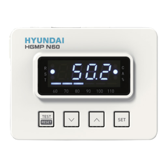
Product Overview HG Series Electronic Motor Protection Relays Optimal motor protection solution for today’s “smart” devices... - Page 3 The HGMP electronic motor protection relay provides protection for the motor system from unstable condition of power system and maximizes utilization rate with user-friendly advanced motor protection functions. Features by Model Type Normal Type Advanced Type Provides core motor protection functions to enable All normal type features are offered, in addition economical and practical motor control. protection function delay can be set in detail to Earth leakage or instantaneous protection functions implement more optimized motor protection system.
-
Page 4: Overview And Characteristics
Electronic Motor Protection Relays Overview and Characteristics Microprocessor-Based Control Advanced 32-bit ARM Core MCU provides precise measurements and calculations, maximizing relay stability and reliability. Wide Current Setting Range Rogowski CT prevents issues with magnetic flux saturation, enabling a high degree of measurement accuracy. Rogowski Coil CT Magnetic Flux Saturation... - Page 5 Electronic Motor Protection Relays Superior Noise Characteristics Run-Time Alert Function Features superior harmonic noise characteristics and can be used Total cumulative motor run time is displayed for convenient for a wide frequency range (30 to 200 Hz), allowing application in scheduling of maintenance and repair.
-
Page 6: Technical Data External Structure
Electronic Motor Protection Relays Technical Data External Structure Integrated type ˙ Main Unit : Control and display monitoring can be performed directly on the main unit of the relay. Tunnel type or screw type can be selected to suit the panel environment. Separated type ˙... - Page 7 Electronic Motor Protection Relays Front Side of Main Unit (Normal Type/Separated Type) No. Type Main Functions ❶ Power Connection Relay Power Cable Connection Terminal Terminal ❹ RESET Button Manual Trip Reset ❷ POWER : Relay Power Status Status Indicator LED FAULT : Trip Activation Indicator ❸ Connector Cable Port Port For Cable Connection to the Display Unit (RJ45) 95-96 Main Contact Functions as b contact for Default 1a1b Setting ❼ 97-98 Main Contact Functions as a contact for Default 1a1b Setting ❺ Instantaneous Type : Serves as Instantaneous ❻ 07-08 Auxiliary and Overcurrent Alert Terminal (07-08) Contact Ground Fault Type : External ZCT Connection Terminal (Z1-Z2) Front Side of Main Unit (Normal Type/Integrated Type) No.
-
Page 8: Functions
Electronic Motor Protection Relays Technical Data Functions Display Unit Button Functions Button Picture Main Functions and Key Information Switch between normal and test modes. Can only be switched when the motor is stopped. TEST TEST/RESET Clears the trip if a trip has occurred. Ensure that the cause of the failure has been removed before resetting. RESET In the menu screen, press to move to the higher settings menu. - Page 9 Electronic Motor Protection Relays Adjusting Settings 1. Enter Test Mode ˙ Stop the motor and verify that the amperage displayed on the ammeter is 0.00 A. ˙ Press the TEST/RESET button to switch to test mode. Verify that “TEST” is indicated on the display as shown. 2. Enter Password ˙...
- Page 10 Electronic Motor Protection Relays Technical Data Adjusting Settings 4-2. Moving between the Settings Menus ( Buttons) ※ This feature is useful for adjusting certain settings while the relay is in operation. ˙ Pressing the at the first settings menu enables cycling through the settings menus. Refer to the table below for the sequence of the menus displayed.
- Page 11 Electronic Motor Protection Relays Settings Sequence and Menus Order Indicator Code Initial Settings Item Description Settings Range Unit Shown Code Displayed Value 0.5, 0.6, … 60.0 Rated Current Set the rated current for the protection characteristics. 0.25, 0.5, 1, 2, … 200 CT Ratios Enter the CT ratio for external CT. Select current Operating time characteristics between definite time/inverse time/ Operating thermal inverse time - dEF (definite time), thr (thermal inverse time), dEF, thr, nthr Time Characteristics nthr(non-thermal inverse time). oFF, 0.2, 0.5, 1, 2, oc-t Set the activation delay (operation time) for the overcurrent characteristics. Activation Delay … 60 Time Profile for oFF, 1, 2, …...
- Page 12 Electronic Motor Protection Relays Technical Data Functions Function Inventory Functions Details Notes Protection from overload damage based on motor’s thermal characteristics Basic function refer to Overcurrent Trip initiated when current exceeds 112.5 % of set rated current, based on operating time cold/hot curve function characteristics (inverse/definite time) Protection from unloaded operation due to motor load breakdown...
- Page 13 Electronic Motor Protection Relays Controls and Settings Trip Cause Indicator Cause of Event Indicator Code Code Displayed Details Overcurrent Under definite time characteristics, trip occurs when current exceeds 112.5 % of set rated (Definite time) current. Under inverse time characteristics, trip occurs when current exceeds set rated current. Overcurrent Reset cannot be carried out when the motor has tripped under thermal inverse time in (Inverse time) order to protect the motor; and reset is possible after a certain span of time has elapsed after the trip. Forcing a reset may cause damage to the motor. Current in excess of the rated current protection factor (200 to 1,000 % of rated current) Lock parameters (limited to overcurrent definite time characteristics) Current in excess of the rated current protection factor (150 to 700 % of rated current) Stall parameters (limited to overcurrent definite time characteristics) Difference between minimum and maximum current between three phases in excess of Phase Failure 70 % Difference between minimum and maximum current between three phases exceeds Phase Unbalance parameters (10 to 70 %) Reverse Phase Detection of phase reversal during motor startup Undercurrent Current flow under rated current factor (30 to 70 % of rated current) parameters Earth Leakage (ZCT) Current in excess of earth leakage current parameters Ground Fault (NCT) Current in excess of ground fault current parameters Current in excess of the rated current protection factor (600 to 1,500 % of rated current)
-
Page 14: Operational Characteristics
Electronic Motor Protection Relays Technical Data Operational Characteristics Contact Characteristics The operational characteristics for the relay’s main contacts (95-96, 97-98) and auxiliary contact (07-08) can be various based on the Cont settings and the Au-c settings. The inverse of normal mode is applied during test mode Menu Setting Contact Output Model... - Page 15 Electronic Motor Protection Relays Contact Output Example for Overcurrent Warning The 07-08 auxiliary contact can be used for overcurrent warning, dedicated ground fault or dedicated instantaneous according to settings. Activating the instantaneous function (Sc) forces the contact to be set for instantaneous. When current flow exceeds overcurrent warning threshold parameters, the warning terminal opens and closes repeatedly every second.
- Page 16 Electronic Motor Protection Relays Technical Data Operational Characteristics Thermal Curve In accordance with IEC 60255-8 Thermal Electrical Relays specifications, protection functions activate based on hot curves and cold curves depending on the thermal characteristics of the load current before an overload can occur. The operating characteristic curves are as shown on the graph, represented as functions of current and time from class 1 to 60.
- Page 17 Electronic Motor Protection Relays Overcurrent Time Characteristics Curves Inverse Time Class 1 Inverse Time Class 10 10,000 10,000 1,000 1,000 Cold Cold 0.01 0.01 Multiples of Rated Current Multiples of Rated Current Inverse Time Class 30 Inverse Time Class 50 10,000 10,000 1,000 1,000 Cold Cold...
- Page 18 Electronic Motor Protection Relays Technical Data Operational Characteristics Overcurrent Time Characteristics Curves Inverse Time Class 60 Definite Time 10,000 10,000 1,000 1,000 Cold t0.2 0.01 0.01 Multiples of Rated Current Multiples of Rated Current...
- Page 19 Electronic Motor Protection Relays Communication Function (Advanced Type) Supports the universal industrial communication protocol RS-485/Modbus to enable easy interfacing into the user’s integrated control network. Main Bus Integrated Control System RS-485/Modbus SCADA Supervisor Installation Compatibility ˙ Can be easily connected to the main circuit terminal block, with both tunnel and screw type connection available to suit the installation environment.
- Page 20 Electronic Motor Protection Relays Model Selection Table Specifications Comparison by Model Electronic Motor Protection Relay Normal – Normal - Advanced – Advanced – Spec Classification Earth Leakage Instantaneous Comm. Disabled Comm. Enabled HGMP N60 Z HGMP N60 I HGMP A60 N HGMP A60 M Protection Functions Overcurrent ● ● ● ● Undercurrent ● ● ● ● Phase Failure ● ● ●...
- Page 21 Electronic Motor Protection Relays Electronic Motor Protection Relays Normal Type – Earth Leakage Normal Type - Instantaneous Advanced Type Classification HGMP N60 Z HGMP N60 I HGMP A60 Panel Installation Type Separated/Integrated Separated Connection Type Screw type/Tunnel type Rated Current 60 : 0.5 ~ 60 A Current Configuration Range Minimum rated current ~ maximum rated current Control Voltage (50/60 Hz) A/DC 100 ~ 240 V Function Overcurrent Over 112.5 % ± 5 % – Definite time, inverse time (thermal, non-thermal) Undercurrent User set (30 to 90 % of rated current) Phase Failure Over 70 ± 10 % of phase current deviation Phase Unbalance Over user set ± 10 % of phase current deviation Stall User set after startup (Over 150 ~ 700 % of rated current) – Definite time only Rotor Lock User set after startup (Over 200 ~ 1,000 % of rated current) – Definite time only Reverse Phase...
- Page 22 Electronic Motor Protection Relays Dimensions Main Unit and Screw Type Unit : mm 22.5 22.5 22.5 22.5 Ø7.5 HYUNDAI U / 2 / T1 V / 4 / T2 W / 6 / T3 HGMP A60M 22.5 22.5 Ø7.5 HYUNDAI...
- Page 23 Electronic Motor Protection Relays Circuit Diagram 3 Phase Circuit FUSE AC 220V LAMP OFF(RESET) TRX+ TRX- HYUNDAI HGMP A60M POWER FAULT COMM HGMP Z1 Z1 3 Phase Circuit (Aux. Terminal : Overcurrent Warning) FUSE AC 220V LAMP OFF(RESET) TRX+ TRX-...
- Page 24 Electronic Motor Protection Relays Circuit Diagram 3 Phase Circuit (Aux. Terminal : Instantaneous) FUSE AC 220V OFF(RESET) LAMP TRX+ TRX- HYUNDAI HGMP A60M POWER FAULT COMM HGMP Z1 Z1 Single Phase Circuit FUSE AC 220V LAMP OFF(RESET) HYUNDAI HGMP A60M...
- Page 25 Electronic Motor Protection Relays With External CT FUSE AC 220V LAMP OFF(RESET) TRX+ TRX- HYUNDAI HGMP A60M HGMP POWER FAULT COMM Z1 Z1 With Earth Leakage Protection ZCT...
- Page 26 Electronic Motor Protection Relays Circuit Diagram Y-Δ with HGMP FUSE AC 220V HYUNDAI HGMP 1 HGMP A60M POWER FAULT COMM Z1 Z1 HYUNDAI HGMP A60M HGMP 2 POWER FAULT COMM Z1 Z1 Detects full load current when wired as HGMP 1, and 1/√3 of full load current (58 %) when wired as HGMP 2.
- Page 27 Electronic Motor Protection Relays Order Code Order Process HGMP F220 Normal Type Panel Product Category Model Name Type and A/F Contact Type Control Voltage Protection Features Installation Type Normal Earth Leakage Separated Tunnel F220 AC/DC 100 ~ 240 V Type Type Unit Type Advanced Instantaneous Integrated Screw Type...
- Page 28 Electronic Motor Protection Relays Optional Component Unit : mm Type HiMP-ZCT 30 HiMP-ZCT 50 HiMP-ZCT 65 56.5 HiMP-ZCT 80 HiMP-ZCT 100 72.5 HiMP-ZCT 120 82.5 Connection Cable Type HGMPCBL1.5 1.5 M HGMPCBL2 HGMPCBL3...
- Page 29 Electronic Motor Protection Relays External CT Unit : mm HiMP-CT80 ~ CT500 Ø6 HiMP-CT630 ~ CT800 4-Ø7 ※ It is not supplied with mounting plate for assembling on the external CT.
- Page 30 Electronic Motor Protection Relays Handling and Maintenance Inspection Storage and Transportation Storage Precaution | Ambient Temperature | -5 ~ +40 °C The surrounding environment may affect the insulation (Below the average daily temperature of 35 °C) performance and durability of the Electronic Motor | Altitude | Below 1,000 m above sea level Protection Relay so the environment condition for usage | Relative Humidity |...
- Page 31 Electronic Motor Protection Relays Handling Precautions Caution ˙ Do not store and use in abnormal environment such as high temperature, high humidity, dust, corrosive gas, vibration, impact and others It may cause electric shock, fire and malfunction. ˙Ensure that rubbish, foreign substances such as concrete powder, metal powder, rainwater and others do not flow in. ˙When handling the product, do not use lubricants.