Table of Contents

Related Manuals for Ariston NIMBUS PLUS M NET


Summary of Contents for Ariston NIMBUS PLUS M NET
- Page 1 NIMBUS PLUS M NET 3300949 3300952 3300950 3300953 3300951 ISTRUZIONI TECNICHE PER L’INSTALLAZIONE E LA MANUTENZIONE TECHNICAL INSTRUCTIONS FOR INSTALLATION AND MAINTENANCE 420000453002...
-
Page 2: Table Of Contents
INDICE Collegamenti elettrici Generalità Circuito elettrico ..................21 Norme di sicurezza ...................3 Tabelle collegamenti elettrci ............... 21 Caratteristiche dell’acqua provvista all’impianto ......6 Connessioni elettriche dell’unità esterna ........23 Descrizione del sistema Connessioni elettriche dell’unità interna ........24 Connessioni elettriche tra unità interna ed unità esterna ..25 Composizione del sistema .............. -
Page 3: Norme Di Sicurezza
NORME DI SICUREZZA Installare l’apparecchio su base solida, non soggetta a vibrazioni. Rumorosità durante il funzionamento. ATTENZIONE seguente manuale costituisce parte Non danneggiare, nel forare la parete, integrante ed essenziale del prodotto. Deve cavi elettrici o tubazioni preesistenti. essere conservato con cura e deve sempre Folgorazione per contatto con conduttori essere allegato al prodotto, anche in caso sotto tensione. - Page 4 tegri e che le parti dotate di moto rotativo Movimentare l’apparecchio con le dovute o alternativo siano correttamente fissate), protezioni e con la dovuta cautela. utilizzarle correttamente, non intralciare Danneggiamento dell’apparecchio o di i passaggi con il cavo di alimentazione, oggetti circostanti per urti, colpi, incisioni, assicurarle da eventuale caduta dall’alto, schiacciamento.
- Page 5 Lesioni personali per contatto di pelle o oc- ATTENZIONE! chi con sostanze acide, inalazione o inge- L’apparecchio può essere utilizzato da bambinni stione di agenti chimici nocivi. di età non inferiore a 8 anni e da persone con Danneggiamento dell’apparecchio o di og- ridotte capacità...
-
Page 6: Caratteristiche Dell'acqua Provvista All'impianto
è quindi fortemente sconsigliato. biente e sulla salute e favorisce il reimpiego e/o riciclo Qualora si utilizzi glicole, Ariston Thermo non risponde dei materiali di cui è composta l’apparecchiatura. delle perdite di efficienza del sistema e raccomanda un corretto dosaggio e manutenzione. -
Page 7: Descrizione Del Sistema
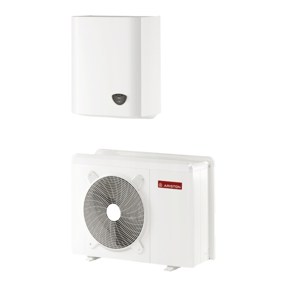
L’unità esterna fornita è uno dei modelli seguenti: • NIMBUS 40 M EXT Composizione del sistema • NIMBUS 50 M EXT Il sistema NIMBUS PLUS M NET composto da: • NIMBUS 70 M EXT - Un’unità interna • NIMBUS 70 M-T EXT - Un’unità... - Page 8 UNITÀ INTERNA WH-L M 1Z Vista complessiva Dimensioni e Pesi 1. Manometro 2. Pressostato 3. Valvola di scarico 4. Sonda di temperatura ritorno dall’impianto di riscaldamento/raffrescamento 5. Valvola di sicurezza 3 bar 6. Vaso d’espansione 7. Degasatore automatico 8. Resistenza elettrica supplementare 9.
-
Page 9: Riscaldamento/Raffrescamento
UNITÀ INTERNA WH M 1Z/2Z Vista complessiva Dimensioni e Pesi (mm) WH M 1 ZONA RISCALDAMENTO/RAFFRESCAMENTO Legenda: 1. Valvola di scarico 2. Valvola di sicurezza 3 bar 3. Manometro 4. Valvola di scarico 5. Pressostato 6. Vaso espansione 7. Degasatore automatico 8. - Page 10 WH M 2 ZONE RISCALDAMENTO/RAFFRESCAMENTO Legenda: Valvola di scarico 2. Valvola di sicurezza 3 bar Manometro Pressostato 5. Sonda di temperatura ritorno dall’impianto di riscaldamento/raffrescamento 6. Sonda temperatura mandata ZONA1 Sonda temperatura ritorno ZONE 1 8. Sonda temperatura mandata ZONE 2 Sonda temperatura ritorno ZONE 2 10.
-
Page 11: Pressione Disponibile
WH M 2 ZONE SOLO RISCALDAMENTO Legenda: 1. Valvola di scarico 2. Valvola di sicurezza 3 bar 3. Manometro 4. Sonda temperatura mandata ZONA1 5. Sonda temperatura ritorno ZONE 1 6. Sonda temperatura mandata ZONE 2 7. Sonda temperatura ritorno ZONE 2 8. - Page 12 PERDITE DI CARICO Perdita di carico correlata al circuito idraulico dell’unità interna In abbinamento all’unità esterna: 40M - 50M - 70M - 70MT EXT In abbinamento all’unità esterna: 90M - 90MT - 110M - 110MT EXT PRESSIONE DISPONIBILE UNITÀ INTERNA Pressione disponibile per l’installazione all’uscita dell’unità...
-
Page 13: Dispositivo Di Controllo Remoto
Aggiungendo una Sonda Esterna Ariston: Classe del controllo di temperatura Contributo all'efficienza energetica % per il riscaldamento degli ambienti In un sistema a 3 zone con 2 Sensori ambiente Ariston: Classe del controllo di temperatura VIII Contributo all'efficienza energetica % per il riscaldamento degli ambienti... -
Page 14: Guida All'installazione
GUIDA ALL’INSTALLAZIONE Scelta del posizionamento • Evitare il posizionamento dell’unità esterna in luoghi di difficile accesso per le successive operazioni di installazione e manu- tenzione. Attenzione • Evitare il posizionamento in prossimità di fonti di calore. L’installazione dell’unità esterna ed interna deve sempre es- •... -
Page 15: Procedura Di Apertura Dei Passaggi Per I Collegamenti
2. Rimozione pannello frontale Attenzione Rimuovere le viti che bloccano il pannello frontale, tirarlo Prima dell’installazione verificare la resistenza e in avanti e verso il basso. l’orizzontalità della base di appoggio. Basandosi sulle immagini sotto riportate, fissare solidamente la base dell’unità... -
Page 16: Unità Interna Installazione Preliminare
UNITÀ INTERNA 2. Scarico valvola di sicurezza WH-L M 1 ZONE Installazione preliminare L’unità interna deve essere posizionata presso un vano con funzione abitativa (evitando possibili rischi di congela- mento) al fine di garantire le migliori prestazioni. Per il posizionamento del sistema utilizzate la dima fornita valvola di ed una livella. -
Page 17: Riempimento Dell'impianto
WH M 2 ZONE WH M 2 ZONE RISCALDAMENTO valvola di sicurezza 3 bar valvola di scarico valvola di scarico valvola di sicurezza 3 bar Provvedere al montaggio del tubo di scarico della valvola di WH M 1 ZONA RISCALDAMENTO sicurezza, presente nella confezione documenti. -
Page 18: Connessioni Idrauliche Unità Interna
CONNESSIONI IDRAULICHE UNITÀ INTERNA VERIFICHE Prima di effettuare i collegamenti idraulici verificare che: • la pulizia dell’impianto sia stata effettuata • non siano presenti impurità nell’acqua di impianto • vengano utilizzati componenti compatibili tra loro (evitare connesioni in ferro e rame insieme) •... -
Page 19: Installazione Finale Dell'intero Sistema Schemi
INSTALLAZIONE FINALE DELL’INTERO SISTEMA ATTENZIONE I collegamenti elettrici devono essere realizzati dopo aver completato tutti i collegamenti idraulici. 1 ZONA WH Il circolatore dell’unità esterna spinge l’acqua verso il sistema di riscaldamento/raffrescamento. L’unità interna è provvista di due resistenze elettriche supplementari da 2kW ed un vaso di espansione. Legenda;... - Page 20 1 ZONE WH-L Il circolatore dell’unità esterna spinge l’acqua verso il sistema di riscaldamento/raffrescamento. L’unità interna è provvista di tre resistenze elettriche supplementari da 2kW ed un vaso di espansione. Legenda: 1. Unità Interna 2. Unità esterna 3. Sonda esterna 4.
-
Page 21: Collegamenti Elettrici
COLLEGAMENTI ELETTRICI Attenzione: I collegamenti elettrici vanno effettuati dopo aver completato tutti i collegamenti idraulici. Attenzione: Dopo il Power OFF dell’unità esterna, sarà necessario attendere almeno 5 minuti prima di eseguire Il Power ON. L’ unità interna e l’unità esterna devono essere alimentate separatamente seguendo quanto indicato sulle tabelle. Tra l’unità interna ed esterna dovrà... - Page 22 Le alimentazioni delle due unità interna ed esterna, devono essere rispettivamente connesse ad un interruttore differenziale a cor- rente residua (RCCB) con soglia di intervento di 30mA. Per l’unità dotata di inverter (unità esterna), si consiglia l’utilizzo di differenziali di tipo B per alimentazioni 3ph e di tipo F o B ( in base all’impianto elettrico a cui viene collegata ) per alimentazioni 1ph.
-
Page 23: Connessioni Elettriche Dell'unità Esterna
ATTENZIONE: Eseguire il collegamento a terra prima di tutti gli altri collegamenti elettrici. Le unità interne ed esterne devono essere alimentate separatamente. Per evitare qualsiasi rischio, il cavo di alimentazione dell’unità esterna ed interna deve essere sostituito solo da tec- nici specializzati . -
Page 24: Connessioni Elettriche Dell'unità Interna
Connessioni elettriche dell’unità interna Prima di ogni intervento sul sistema, interrompere l’alimenta- zione dall’interruttore generale. Rispettare le connessioni di neutro e fase. Per accedere al quadro elettrico dell’unità interna, rimuovere le tre viti indicate in figura (A) ed estrarre il coperchio del quadro elettrico (B). -
Page 25: Connessioni Elettriche Tra Unità Interna Ed Unità Esterna
Connessioni elettriche tra unità interna ed unità esterna Prima di ogni intervento sul sistema, interrompere l’alimentazione dall’interruttore generale. 1 ph 3 ph 30mA 30mA EH1 EH1 ST1 ST1 ANODE TA 1 TA 2 TNK BUF +24V AUX 1 NOTA Si raccomanda di verificare la presenza di dispositivi di protezione da sovralimentazioni (SPD) nella linea MT e la presenza di interruttori di sicurezza differenziali e di interruttori magnetotermici in uscita al quadro elettrico che ali- menta l’unità... -
Page 26: Schema Elettrico - Quadro Unità Esterna
SCHEMA ELETTRICO - QUADRO UNITÀ ESTERNA Magnetic ring 1 PH (4kW - 5kW - 7kW) 3 tours FLOW METER INVERTER 1 PH PUMP Program ARM EPROM white Program CN10 white CN25 FLOW Magnetic ring CN13 CN10 CN11 3 tours Valv 4 HEAT P8-1 P8-2... - Page 27 SCHEMA ELETTRICO - QUADRO UNITÀ ESTERNA 3 PH (9kW - 11kW) Capacitor Board R1250RJA FLOW METER 5 mH/12A PUMP KLIXON Magnetic ring Magnetic ring CN622 DC+IN 3 tours Protection Board 3 tours CN602 U-IN U-OUT FLOW CN10 CN11 CN13 V-OUT V-IN blue W-IN...
-
Page 28: Schema Elettrico - Quadro Unità Interna
SCHEMA ELETTRICO - QUADRO UNITÀ INTERNA WH-L BK = Nero YE = Giallo BN = Marrone GN = Verde BU = Blu GY = Grigio RD = Rosso WH = Bianco OR = Arancio PI = Rosa ELECTRICAL RESISTANCE BACK UP INTERFACE SAFETY THERMOSTAT... - Page 29 SCHEMA ELETTRICO - QUADRO UNITÀ INTERNA WH 1 ZONA BK = Nero YE = Giallo BN = Marrone GN = Verde BU = Blu GY = Grigio RD = Rosso WH = Bianco OR = Arancio PI = Rosa ELECTRICAL RESISTANCE BK BK BACK UP...
- Page 30 SCHEMA ELETTRICO - QUADRO UNITÀ INTERNA WH 2 ZONE BK = Nero YE = Giallo INTERNAL SESNOR BN = Marrone GN = Verde PWM 2 BU = Blu GY = Grigio PWM 1 ZONE MANAGER RD = Rosso WH = Bianco MIXING VALVE OR = Arancio PI = Rosa...
-
Page 31: Installazione Dell'interfaccia Di Sistema
INSTALLAZIONE DELL’INTERFACCIA DI SISTEMA Posizionamento L’interfaccia di sistema riconosce la temperatura ambiente, per cui si deve tener conto di questo fattore nello sce- gliere il posizionamento della stessa. Si consiglia un posizionamento lontano da fonti di calore (radiatori, esposizione diretta alla luce solare, camini etc.) così... - Page 32 Interfaccia di sistema simboli display: Tasti e display: 1. tasto indietro « «(visualizzazione precedente) Estate / Impostazioni acqua calda 2. manopola ) Inverno 3. tasto «OK» Solo riscaldamento (conferma l’operazione o accede al menu principale) 4. DISPLAY Raffrescamento Solo raffrescamento OFF sistema spento Programmazione oraria Funzionamento manuale...
-
Page 33: Procedura Di Accensione
- Energy Manager ATTENZIONE - Controllo multi zona Per garantire la sicurezza e il corretto funzionamento dell’interfaccia di sistema, la messa in funzione deve Per impostare la zona corretta a cui è associata l’inter- essere eseguita da un tecnico qualificato in possesso faccia di sistema ruotare la manopola e selezionare: dei requisiti di legge. - Page 34 Ogni richiesta di calore, di raffrescamento e acqua cal- 17.2.1 Termoregolazione da sanitaria viene interrotta mentre le logiche di prote- Attiva/disattiva la funzione di termoregolazione. zione antigelo sono attive 17.2.2 Modalità riscaldamento 17.1.1 HV IN 2 (ingresso configurabile a 230V) Definisce il ritardo di accensione delle resistenze di inte- - Non definito: nessuna funzione associata all’ingresso.
- Page 35 17.4 RAFFRESCAMENTO Premere il tasto OK. Ruotare la manopola e selezionare: 17.4.0 Attivazione modalità raffrescamento 17.7 MODO MANUALE - 2 - Non attivo 17.7.1 Forza la pompa in riscaldamento - Attivo Attiva la pompa di calore in riscaldamento, la frequenza 17.4.1 Impostazione ritardo accensione raffrescamento del compressore è...
- Page 36 RESET MENU 18 giorni seguenti) Cancella impostazioni di fabbrica. CONNETTIVITÀ Premere il tasto OK. Dopo aver verificato la disponibilità del servizio Ariston Net nel proprio paese seguire le istruzioni riportate nel KIT SENSYS NET. BUFFER Premere il tasto OK. Ruotare la manopola e selezionare: 20.0...
-
Page 37: Termoregolazione
TERMOREGOLAZIONE La verifica dell’idoneità della curva scelta richiede un tem- Per impostare i parametri di termoregolazione premere po lungo nel quale potrebbero essere necessari alcuni contemporaneamente i tasti indietro “ “ e “OK” fino alla aggiustamenti. Al diminuire della temperatura esterna (in- visualizzazione sul display “Inserimento codice “. - Page 38 TERMOREGOLAZIONE RAFFRESCAMENTO All’aumentare della temperatura esterna (estate) si posso- Per impostare i parametri di raffrescamento premere con- no verificare tre condizioni: temporaneamente i tasti indietro “ “ e “OK” fino alla 1. la temperatura ambiente aumenta, questo indica che bi- visualizzazione sul display “Inserimento codice “.
-
Page 39: Tabella Menu
IMPOSTAZIONE DESCRIZIONE RANGE DI FABBRICA RETE Rete BUS Interfaccia di sistema Energy Manager Rete BUS attuale Pompa di calore Sensore ambiente Controllo multi zona Interfaccia di sistema Nessuna zona selezionata Numero zona Zona selezionata Correzione temperatura ambiente - 3; +3 Versione SW interfaccia PARAMETRI ZONA 1 Impostazione Temperature... - Page 40 IMPOSTAZIONE DESCRIZIONE RANGE DI FABBRICA Velocità fissa Modulazione pompa zona Modulante su deltaT Modulante su deltaT Modulante su pressione DeltaT obbiettivo per modulazione 4 ÷ 25°C 7°C (LT) - 20°C (HT) Velocità fissa pompa 20 ÷ 100% 100% Raffrescamento T Set Z1 Raffrescamento par.
- Page 41 IMPOSTAZIONE DESCRIZIONE RANGE DI FABBRICA Temperatura mandata sola lettura Temperatura ritorno sola lettura Stato Richiesta Calore Z2 OFF - ON sola lettura Stato Pompa OFF - ON sola lettura Dispositivi Zona 2 Velocità fissa Modulazione pompa zona Modulante su delta T Modulante su delta T Modulante su pressione DeltaT obbiettivo per modulazione...
- Page 42 IMPOSTAZIONE DESCRIZIONE RANGE DI FABBRICA Ultimi 10 errori 2 Reset Lista Errori 2 Resettare? OK=Sì, esc=No Reset Menu Ripristino Impost di Fabbrica Resettare? OK=Sì, esc=No Ripristino Impost di Fabbrica 2 Resettare? OK=Sì, esc=No PARAMETRI SISTEMA POMPA DI CALORE Parametri utente Modalità...
- Page 43 IMPOSTAZIONE DESCRIZIONE RANGE DI FABBRICA Tempo Incremento Temp Risc 0 ÷ 60 min. 16 min. Correzione T esterna -3 ÷ +3°C 0°C 1 stadio Stadi di attivazione resistenza 2 stadi 2 stadi 3 stadi Presenza anodo Pro-Tech OFF - ON Abilitazione antibloccaggio circolatore OFF - ON Riscaldamento - 1...
- Page 44 IMPOSTAZIONE DESCRIZIONE RANGE DI FABBRICA Resistenza elettrica 3 OFF - ON Anodo Pro-Tech OFF - ON Modo manuale - 2 Attivazione modalità manuale OFF - ON Forza la pompa in riscaldamento OFF - ON Forza la pompa in raffreddamento OFF - ON Modalità...
- Page 45 IMPOSTAZIONE DESCRIZIONE RANGE DI FABBRICA Temp ritorno acqua pompa calore sola lettura Temp evaporatore sola lettura Temp aspirazione compr. sola lettura Temp mandata compr. sola lettura Temp del refrigerante sola lettura sola lettura Diagnostica Pompa Calore - 2 Stand by Raffrescamento Riscaldamento Modalità...
- Page 46 IMPOSTAZIONE DESCRIZIONE RANGE DI FABBRICA Diagnostica scheda -1 Ingressi stand-by antigelo riscaldamento sanitario funzione sanificazione termica funzione disareazione funzione chimney Ciclo asciugatura del massetto no generazione calore modo manuale Stato sistema errore sola lettura inizializzazione raffrescamento Antigelo Sanitario Integrazione fotovoltaico Deumidificazione recupero refrigerante Sbrinamento...
- Page 47 IMPOSTAZIONE DESCRIZIONE RANGE DI FABBRICA Configurazione rete Configurazione WPS Orario Internet Info Connettività Inizializzazione Idle Inizializzazione Acess Point Modalità Acess Point Stato connettività Connessione WiFI in corso WiFi connessa Connessione cloud in corso Cloud connesso Errore WiFi Livello del segnale Non collegato Stato dell'attivazione Non attivo...
-
Page 48: Manutenzione
MANUTENZIONE Informazioni per l’utilizzatore Informare l’utilizzatore sulle modalità di funzionamento del sistema installato. ATTENZIONE In particolare consegnare all’utilizzatore il manuale d’istru- Per garantire la sicurezza e il corretto funzionamento la ma- zioni, informandolo della necessità di conservarlo in pros- nutenzione deve essere eseguita da un tecnico qualificato in simità... -
Page 49: Lista Errori Unità Interna
LISTA ERRORI UNITÀ INTERNA ERRORE DESCRIZIONE RISOLUZIONE - Attivazione della termoregolazione basata sulla sonda esterna. Sonda Esterna Difettosa - Sonda esterna non connessa o danneggiata. Sovraccarico alimentazione bus Sonda Mandata Z1 Difettosa Sonda Mandata Z2 Difettosa Sonda Mandata Z3 Difettosa Sonda Ritorno Z1 Difettosa Sonda Ritorno Z2 Difettosa Sonda Ritorno Z3 Difettosa... -
Page 50: Lista Errori Unità Esterna
- Controllare l’attivazione del circolatore principale Termostato resistenza elettrica (auto) - Controllare il flusso con il valore flussimetro tramite il parametro 17.11.3 - Controllare lo stato del termostato di sicurezza e cablaggi Selezionare configurazione del contatto Parametro 17.5.2 = HP-HC o HP-HC 40°C e parametro 17.1.0 = assente tariffa ridotta (FR) Errore pre-circolazione Flusso non rilevato per 5 minuti durante la pre-circolazione... -
Page 51: Lista Errori Inverter
LISTA ERRORI INVERTER LISTA ERRORI INVERTER ODU 9-11 1-PHASE ERRORE ERRORE DESCRIZIONE 1ph 3ph DESCRIZIONE INVERTER INVERTER Sovratemperatura Dissipatore ERRORE SENSORE CORRENTE U DEL COMP Sovracorrente IPM Compressore ERRORE SENSORE CORRENTE V DEL COMP Start-up Compressore Fallito ERRORE SENSORE CORRENTE W DEL COMP Sovracorrente Compressore ERRORE SENSORE CORRENTE PFC Mancanza di fase AC Ingresso... -
Page 52: Targhette Caratteristiche
L’unità esterna facente parte del prodotto acquistato è fornita con l’etichetta energetica relativa ad una specifica configurazione, in ot- temperanza a quanto previsto dal Regolamento 811/2013; qualora la configurazione da voi scelta non corrisponda a quella in etichetta, è possibile recuperare l’etichetta corretta sul sito www.ariston.com o telefonando al n.ro clienti +39 0732 633528. 52 / IT... - Page 53 INDEX Overview Electrical wiring Safety regulations .................. 54 Electrical circuit ..................71 Table of electrical connections ............71 Characteristics of the water supplied to the appliance ..... 56 External Unit electrical connection ............73 System description Internal Unit electrical connection .............74 Electrical connections between internal and external unit ..75 System compositions ................
- Page 54 SAFETY REGULATIONS Fire caused by overheating due to electrical cur- rent passing through undersized cables. CAUTION This manual constitutes an integral and essential Protect all connection pipes and wires in order part of the product. It must be kept with care and to prevent them from being damaged.
- Page 55 Make sure any rolling ladders are positioned Reset all the safety and control functions af- securely, that they are suitably strong, that the fected by any work performed on the applian- steps are intact and not slippery and that the ce and make sure they operate correctly befo- ladders are fitted with handrails on either side re restarting the appliance.
- Page 56 If gly- centre. col is used, Ariston will not be responsible for system The waste disposal centre (which using special treat- efficiency losses and recommends a correct dosage and ment and recycling processes effectively dismantles maintenance.
- Page 57 SYSTEM DESCRIPTION EXTERNAL UNIT As external unit, one of the following models is provided: System composition NIMBUS COMPACT M system consists of: • NIMBUS 40 M EXT - External unit • NIMBUS 50 M EXT - Internal unit • NIMBUS 70 M EXT - System interface •...
- Page 58 INTERNAL UNIT WH-L M 1Z Overall view Weights and dimensions (mm) 1. Manometer 2. Pressure switch 3. Discharge valve 4. Temperature sensor (return form the installa- tion) heating/cooling 5. Safety valve 3 bar 6. Expansion vessel 7. Automatic air purge 8.
- Page 59 INTERNAL UNIT WH M 1Z/2Z Overall view Weights and dimensions (mm) WH M 1 ZONE HEAT/COOL 1. Discharge valve 2. Safety valve 3 bar 3. Manometer 4. Discharge valve 5. Pressure switch 6. Expansion vessel 7. Automatic air purge 8. Temperature sensor (flow to the installation) heating/cooling 9.
- Page 60 WH M 2 ZONE HEAT/COOL 1. Discharge valve 2. Safety valve 3 bar 3. Manometer 4. Pressure switch 5. Temperature sensor (return from the installa- tion) heating/cooling 6. Temperature sensor to the ZONE 1 7. Temperature sensor return from ZONE 1 8.
- Page 61 WH M 2 ZONE ONLY HEAT 1. Discharge valve 2. Safety vlve 3 bar 3. Manometer 4. Temperature sensor to the ZONE 1 5. Temperature sensor from the ZONE 1 6. Temperature sensor to the ZONE 2 7. Temperature sensor from the ZONE 2 8.
- Page 62 AVAILABLE PRESSURE AT INTERNAL UNIT Available pressure at internal unit outlet towards the system. Coupled with external units: Coupled with external units: 40M EXT - 50M EXT - 70 M EXT - 70MT EXT 90M - 90MT - 1110M - 10MT EXT AVAILABLE PRESSURE AT INTERNAL UNIT Available pressure at internal unit outlet towards the system.
- Page 63 Adding an ARISTON OUTDOOR SENSOR: Class of the temperature control Contribution to seasonal space heating energy efficiency in % In a 3-zones system with 2 ARISTON ROOM SENSORS Class of the temperature control VIII Contribution to seasonal space heating energy efficiency in %...
- Page 64 INSTALLATION GUIDE • Do not place the external unit on structures that do not guarantee support. • Avoid placing it in close proximity to fuel tanks of gas. Warning • Avoid a positioning that provides exposure to oil vapors. The appliance must be installed by a qualified techni- •...
- Page 65 2. Removal of frontal panel Attention Remove the screws that block the frontal panel and pull it Before installation, check strength and horizontality of forward and down. the base. Based on the pictures, connect the base of the external unit firmly to the ground, using suitable anchor bolts (M10 x 2 pairs).
- Page 66 INTERNAL UNIT 2. Safety valve drain WH-L M 1 ZONE Preinstallation The indoor unit should be positioned in a compartment at home (to avoid risk of freezing) ,in order to ensure the best safety valve 3 bar performance. Use the template provided and a spirit level for positioning the system.
- Page 67 WH M 2 ZONE WH M 2 ZONE HEATING safety valve 3 air purge valve air purge valve safety valve 3 bar WH M 1 ZONE HEATING Assemble the drain pipe of the safety valve, included in the package documents. 3.
- Page 68 HYDRAULIC CONNECTIONS ON INDOOR MODULE Before carrying out the water circuit connections, check that: • the system has been cleaned • there are no impurities in the circuit water • compatible components are used (do not connect copper and steel to each other) •...
- Page 69 FINAL INSTALLATION OF THE WHOLE SYSTEM Attention The electrical connections are made after completing all hydraulic connections 1 ZONE WH The circulation pump which drives the fluid between the external unit and the heating/cooling system in positioned in the external unit. The unit also has two “2 kW” heating elements and an expansion vessel. Legend: 1.
- Page 70 1 ZONE WH-L The circulation pump which drives the fluid between the external unit and the heating/cooling system in positioned in the external unit. The unit also has three “2 kW” heating elements and an expansion vessel. Legend: 1. Internal unit 2.
- Page 71 ELECTRICAL WIRING ATTENTION: The electrical connections shall be made after completing all hydraulic connections. ATTENTION: After Power OFF of the external unit, is needed to wait at least 5 minutes before turn it ON again. The internal and external units must be powered separately according to what is indicated on the tables. Between the internal and external units should also be made a EBUS 2 connection.
- Page 72 Power supplies of the indoor and the outdoor units are to be respectively connected to a Residual Current operated Circuit-Breaker (RCCB) with threshold of 30mA. For inverter driven units (outdoor unit), it is advisable the use of type B residual current device for 3Ph power supplies and type B or F for 1Ph power supplies (depending on the electrical system to which it is connected).
- Page 73 WARNING: Make ground connection prior to any other electrical connections. The internal and external units must be powered separately. To prevent any risk, the power supply cable of the outdoor and indoor unit must only be replaced by the technicians of the after-sales service.
- Page 74 Internal Unit electrical connection Before any operation on the system, turn off the main power. Observe the phase and neutral connections. To access the control panel of the internal unit, proceed as follows: Re- move the three screws (A) indicated in figure and remove the cover of the electrical panel (B).
- Page 75 Electrical connections between internal and external unit Before any work on the system, shut off the power at the breaker. 1 ph 3 ph 30mA 30mA EH1 EH1 ST1 ST1 ANODE TA 1 TA 2 TNK BUF +24V AUX 1 NOTE It is strongly recommended to verify the presence of a surge protection device (SPD) on main power line and of circuit breakers connected to the external and internal unit’s control box...
- Page 76 ELECTRICAL SCHEME - BOX OF EXTERNAL UNIT Magnetic ring 1 PH (4kW - 5kW - 7kW) 3 tours FLOW METER INVERTER 1 PH PUMP Program ARM EPROM white Program CN10 white CN25 FLOW Magnetic ring CN11 CN13 CN10 3 tours Valv 4 HEAT P8-1...
- Page 77 ELECTRICAL SCHEME - BOX OF EXTERNAL UNIT Capacitor Board 3 PH (9kW - 11kW) R1250RJA FLOW METER 5 mH/12A PUMP KLIXON Magnetic ring Magnetic ring CN622 DC+IN 3 tours Protection Board 3 tours CN602 U-OUT U-IN FLOW CN10 CN11 CN13 V-OUT V-IN blue...
- Page 78 ELECTRICAL SCHEME - BOX OF INTERNAL UNIT WH-L BK = Black YE = Yellow BN = Brown GN = Green BU = Blue GY = Grey RD = Red WH = White OR - Orange PI = Pink ELECTRICAL RESISTANCE BACK UP INTERFACE SAFETY...
- Page 79 ELECTRICAL SCHEME - BOX OF INTERNAL UNIT WH 1Z BK = Black YE = Yellow BN = Brown GN = Green BU = Blue GY = Grey RD = Red WH = White OR - Orange PI = Pink ELECTRICAL RESISTANCE BK BK BACK UP...
- Page 80 ELECTRICAL SCHEME - BOX OF INTERNAL UNIT WH 2Z BK = Black YE = Yellow INTERNAL SESNOR BN = Brown GN = Green PWM 2 BU = Blue GY = Grey PWM 1 ZONE MANAGER RD = Red WH = White MIXING VALVE OR - Orange PI = Pink...
- Page 81 INSTALLATION OF SYSTEM INTERFACE Positioning The system interface recognizes the temperature of the environ- ment, so this factor must be taken in consideration during the choice of the positioning of the same. We recommend to place the remote control away from sources of heat (radiators, direct exposure to sunlight, fireplaces etc.) as well as positioning near drafts or openings to the outside which may affect the operation of system interface, should be avoided.
- Page 82 Display symbols: Buttons and Display: 1. back button (previous screen) Summer / DHW settings ) Winter 2. knob button Only Winter / CH settings (to confirm operation or access main menu) Cooling 4. DISPLAY OFF, system off ) Time program ) Manual operation Desired room temperature Room temperature detected...
- Page 83 Turn the knob and select: WARNING - COMPLETE MENU To guarantee safety and correct operation of the system Press the OK button to confirm. Turn the knob and select: interface, it must be commissioned by a qualified techni- HP SYSTEM PARAMETERS cian in possession of the skills as required by law.
- Page 84 17.1.2 HV Input 3 17.2.5 External temperature correction - 0. Not active Offset compensation of the external tempearture probe - 1. PV integration active: Input not active (0V), no tank reading integration from PV system. Input active (230V): if the 17.2.6 Active Resistance Stages system is in stand-by, the DHW setpoint temperature is Define the number of active stages of the heating resistors...
- Page 85 - Always Active Push OK button. Turn the knob and select: - HC/HP 17.8 TEST & UTILITIES NOTE: The hot water storage is heated only by the heat Press the OK button to confirm. Turn the knob and select: pump when the EDF input is enabled (see par. 17.1.0) and 17.8.0 Air-purge function switches to 230V (reduced rate electricity supply).
- Page 86 Reset Factory Settings. CONNECTIVITY Press the OK button. After checking the availability of the Sensys NET service in your country, follow the instructions in the Sensys NET. Push OK button. Turn the knob and select: BUFFER 20.0 CONFIGURATION 20.0.0 Buffer Activation Period (days) Active Buffer mode 20.0.1 Buffer charge mode...
- Page 87 THERMOREGULATION The checking process for the suitability of the curve re- To set the temperature adjustment parameters, simultane- quires a long period of time during which several adjust- ously press and hold the back “ “ and “OK” buttons until ments may be necessary.
- Page 88 To set the temperature adjustment parameters, simultane- When the outdoor temperature rises (summer), three con- ously press and hold back “ “ and “OK” buttons until ditions may arise: “Enter code” appears on the display. Turn the knob to en- 1.
- Page 89 DESCRIPTION RANGE DEFAULT NETWORK BUS network System interface Energy Manager Network presence Heat Pump Room Sensor Zone Manager System interface No zone selected Zone number Zone selected Room temperature correction - 3; +3 SW Version Interface ZONE1 PARAMETERS Setpoint T Day 10 - 30 °C 19°C Heat - 24°C Cool T Night...
- Page 90 DESCRIPTION RANGE DEFAULT Offset [-2,5°C; +2,5°C] 0°C MinT -12°C [FC]; 12°C [FC]; Max T MinT - 23°C [UFH] 23°C [UFH] 7°C [FC]; Min T 7°C-MaxT [FC]; 18-MaxT [UFH] 18°C [UFH Target deltaT for pump modulation cooling [-5; -20°C] -5°C ZONE 2 PARAMETERS (IF PRESENT) Setpoint T Day 10 - 30 °C...
- Page 91 DESCRIPTION RANGE DEFAULT ON/OFF Thermoregulation type Fix Flow T ON/OFF Outdoor T Only Slope [18;33] FC; [0-30] UFH 25 FC; 10 UFH Offset [-2,5°C; +2,5°C] 0°C MinT -12°C [FC]; 12°C [FC]; Max T MinT - 23°C [UFH] 23°C [UFH] 7°C [FC]; Min T 7°C-MaxT [FC];...
- Page 92 DESCRIPTION RANGE DEFAULT Not Defined Absent HV Input 2 Absent DLSG Not active HV Input 3 Not active PV Integration Active None AUX Input 1 None Humidistat sensor None Fault alarm AUX Output 1 (AFR) Humidistat alarm None External heat request Cooling request None Fault alarm...
- Page 93 DESCRIPTION RANGE DEFAULT Disabled Time based Always Active Comfort Function Green Mode HC-HP HC-HP 40°C Green Mode Max HP charging time 30 ÷ 240 min. 120 min. Antilegionella Function ON - OFF Antilegionella start time [hh:mm] [00:00-24:00] 01:00 Thermal Cleance Cycle frequency 24h ÷...
- Page 94 DESCRIPTION RANGE DEFAULT Resistor Stage 3 running hours (h/10) only read Resistor Stage 1 On cycles (n/10) only read HP Defrost hours (h/10) only read Cooling running hours (h/10) only read Heating running hours (h/10) only read DHW running hours (h/10) only read HP Diagnostics - 1 Outside air temperature...
- Page 95 DESCRIPTION RANGE DEFAULT Stand-by Antifreeze Cycle Heating Cycle DHW Cycle Thermal Cleanse Function Air Purge Function Chimney Function Floor drying cycle No Heat Generation Manual Mode Energy Manager Status only read Error Initialization Cool Mode DHW Antifreeze Photovoltaic Integration Dehumidification Pump Down Buffer Heating+DHW Serving Buffer Cooling+DHW Serving...
- Page 96 DESCRIPTION RANGE DEFAULT Initialization Idle Acess Point initializing Acess Point mode on Connectivity Status Station Mode - Connecting Station Mode - Connected Station Mode - Provisioning Station Mode - Server Connected Wifi error Signal Level Not provisioned Active Status Provisioned - Not active Active Serial Number Initialization...
- Page 97 MAINTENANCE Antifreeze function of the external unit The main circulator of the internal unit starts at the minimum Maintenance is an essential operation to insure safety, correct speed when the measured temperature by the return working and duration of life of the appliance. water temperature (EWT) sensor is below 7°C in heating It must be carried out in accordance with the regulations in force.
- Page 98 INTERNAL UNIT ERROR LIST ERROR DESCRIPTION TROUBLESHOOTING Activation of thermoregulation based on outdoor sensor and outdoor Outdoor Sensor Damaged sensor not connected or damaged Bus supply overload Zone1 Send Probe Damaged Zone2 Send Probe Damaged Zone3 Send Probe Damaged (N/A) Zone1 Return Probe Damaged Zone2 Return Probe Damaged Zone3 Return Probe Damaged (N/A)
- Page 99 - Check main circulation activation First thermostat of resistance (auto) - Check water flow by par 17.11.3 - Check safety thermostat status and wirings Check main circulation activation Second thermostat of resistance (manual) - Check water flow by par 17.11.3 - Check safety thermostat status and wirings Night tariff contact not present - Par 17.5.2 = HP-HC or HP-HC 40°C and par.
- Page 100 INVERTER ERROR LIST ODU 9-11 1-PHASE INVERTER ERROR LIST INVERT- ERRORE DESCRIPTION 1ph 3ph DESCRIZIONE INVERTER ERROR Heat Sink-Overheat COMPRESSOR U CURRENT SENSOR FAULT=1 COMPRESSOR V CURRENT SENSOR FAULT Compressor Ipm Over-Current COMPRESSOR W CURRENT SENSOR FAULT Compressor Fail To Drive PFC CURRENT SENSOR FAULT Compressor Over-Current IPM TEMPERATURE SENSOR FAULT...
- Page 101 In compliance with 811/2013 EU Regulation, the outdoor unit which is part of the system purchased carries a label related to a specific configuration; in case the system you chose does not match the one on the label, it is possible to retrieve the appriopriate label at www.ariston.co.uk or by calling our Customer Centre at +44 0333 240 8777. 101 / GB...
- Page 102 102 / GB...
- Page 103 103 / GB...
- Page 104 Ariston Thermo SpA Viale Aristide Merloni, 45 60044 Fabriano (AN) Italy Telefono 0732 6011 Fax 0732 602331 info.it@aristonthermo.com...