Advertisement
Quick Links
Advertisement

Summary of Contents for Mitel T941AM8
- Page 1 T941AM8 ALARM MODULE INSTALLATION GUIDE...
- Page 2 The information is subject to change without notice and should not be construed in any way as a commitment by Mitel or any of its affiliates or subsidiaries. Mitel and its affiliates and subsidiaries assume no responsibility for any errors or omissions in this document.
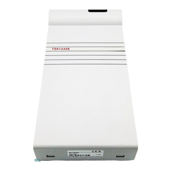
- Page 3 LARM ODULE NSTALLATION UIDE 1 INTRODUCTION T941AM8 has 8 physical inputs for connection to external alarm devices. Inputs are galvanically isolated, have transient protection, and can be programmed for making or breaking contacts. Figure 1. The Alarm Module. Supply voltage: 12.5 V DC ±...
- Page 4 T941AM8 A LARM ODULE NSTALLATION UIDE 1.1 CIRCUIT BOARD OVERVIEW LEDO1 SW02 LEDO2 SWO1 ICO1 ICO2 IC03 LED10 RE01 LED03 S01 S02 Figure 2. The circuit board of the Alarm Module. 58/1531-ANF 901 43 Uen E1 2016-03-18...
-
Page 5: Installation
T941AM8 A LARM ODULE NSTALLATION UIDE 2 INSTALLATION The alarm module should be placed in a dry environment with a temperature range of 0 to +40°C. The figure below shows dimensions for installing the alarm module. Dimensions (H x W x D) - Page 6 T941AM8 A LARM ODULE NSTALLATION UIDE 2.1 INSTALLATION TOGETHER WITH OTHER UNITS Figure 5. Mounting two units together. Remove upper and lower covers. The lower rectangular covers are used to fasten units to each other (1). Fasten the module with three screws; see...
- Page 7 T941AM8 A LARM ODULE NSTALLATION UIDE 3 ADDRESSING Select the proper address by setting address selector switch SW01. The address must not be 00 nor the same as any other 900 unit address. SW01 Figure 6. Addressing switch on the Alarm Module.
- Page 8 T941AM8 A LARM ODULE NSTALLATION UIDE 3.1 HOW TO SET THE ADDRESS The address consists of two hexadecimal digits that are selected by the eight sections of the address switch. The eight sections are divided into two groups, each with four sections (1-4 and 5-8).
-
Page 9: Wiring Runs
T941AM8 A LARM ODULE NSTALLATION UIDE 4 WIRING RUNS The plastic partition (shaded in figure 8) is scored to facilitate breaking at convenient intervals. Figure 8. Breaking the partition for wiring. Use pliers to break off a suitable section. Run the wiring out through the partition. - Page 10 T941AM8 A LARM ODULE NSTALLATION UIDE 5 CONNECTION OF SYSTEM BUS Figure 10. Connection of system bus with modular bus cable. • Connect modular bus cabling to J01 and J02 (1) or if required • Connect two-wire connection to J03 screw 5 and 6 (2)
-
Page 11: Connection Of Supply Voltage
T941AM8 A LARM ODULE NSTALLATION UIDE 6 CONNECTION OF SUPPLY VOLTAGE Supply voltage is connected to screw 1 and 2 of screw connector J03 (see figure 11). 58/1531-ANF 901 43 Uen E1 2016-03-18... - Page 12 T941AM8 A LARM ODULE NSTALLATION UIDE 7 CONNECTION OF ALARM INPUTS FOR VOLTAGE-FREE MAKE/BREAK Connect twisted-pairs to alarm inputs that are to be used: J07 for inputs 1-4 and J08 for 5-8. Connect supply voltage to J09. This can be taken from J03-3 and -4. However, for galvanic isolation an external power supply must be connected to J09.
-
Page 13: Installation Test
T941AM8 A LARM ODULE NSTALLATION UIDE 8 INSTALLATION TEST After the installation, a functional check is made. If a malfunction occurs, check that the functional indicator (LED) on the unit shows a steady light. If not proceed as follows. Function indicator Figure 13. - Page 14 T941AM8 A LARM ODULE NSTALLATION UIDE 9 PROGRAMMING System settings in the Alarm Module are factory set. Default settings are: • Information is transmitted to the Basic Alarm Manager in the CPDM when an input is opened or closed. 58/1531-ANF 901 43 Uen E1 2016-03-18...