Table of Contents
Advertisement
Quick Links
Advertisement
Table of Contents

Summary of Contents for Chicago Pneumatic CPLT
- Page 1 Instruction Manual and Parts List for Light Tower CPLT...
- Page 3 Instruction Manual and Parts List for Light Tower CPLT Instruction manual .................. 5 Parts list ....................25 Printed Matter N° 1310 3012 13 06/2009...
- Page 4 CPLT Warranty and Liability Limitation Use only authorized parts. Any damage or malfunction caused by the use of unauthorized parts is not covered by Warranty or Product Liability. The manufacturer does not accept any liability for any damage arising for modifications, addi- tions or conversions made without the manufacturer's approval in writing.
-
Page 5: Table Of Contents
While every effort has been made to ensure that the information in this manual is correct, Chicago Pneumatic does not assume responsibility for possible errors. Chicago Pneumatic reserves the right to make changes without prior notice. -
Page 6: Specifications
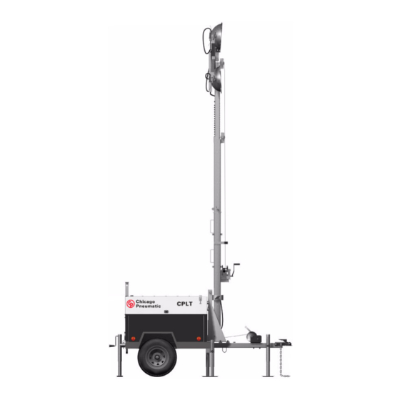
The light tower CPLT mast can be extended vertically up to 31 ft (9,44 m) using simple hand winch operations. The head (all 4 light units) can be rotated 360°, and each light unit can be rotated independently through 180°... -
Page 7: Performance
U- bolts Type Permanent magnet Standard brushless Make Steel Standard Model CPLT Make Maximum speed 50 mile/h (80 km/h) Model G24N1-001 Tires 5.30" x 12" 6 poly tire Rated output, class H temp. rise (ISO8528-3) 105 kVA... -
Page 8: Cubicle
CPLT Identifying instruments and controls 1.6.5 Controller Type Enclosed metal control 2.1 Operation panel Standard None Make Deep Sea Electronics LIGHTS IGNITION Model DSE701 Protections Each lamp has a 10A fuse. 12 V supply has a 3 A fuse. Visual alarms... -
Page 9: Light Tower Operation
Press and hold down the engine starter (3) to crank the engine. 3.1 Safe operation There will be a time delay before the engine starts to For best results on the CPLT appropriate and safe operating crank. If the engine does not start at first attempt, DO NOT procedures are mandatory. -
Page 10: Set Up Procedure Light Tower Mast
3.2 Set up procedure light tower mast The CPLT light tower assembly is constructed of a three section telescopic mast that can be raised and lowered by using two hand 2. First lower the front leg (on the tong bar) so this will provide support once the hitch has been removed from the vehicle. - Page 11 Instruction manual Once the post is in vertical position, adjust the post height by Pull the post safety pin in order to be able to turn and lower the handling the leveler clock wise until the post is in contact with post and return the pin to the safe position.
- Page 12 CPLT 6. Remove the vertical safety pin of the light tower mast in order to 7. Pull and remove the horizontal mast safety pin in order to be able be able to move the mast to its vertical position. to unfold the mast.
- Page 13 Instruction manual 8. Now you are able to unfold the mast. 9. Once the mast has been unfolded and is locked in the vertical position, you can raise and set the height of lamps using the hand Unfold the light tower mast by handling the leveler and turning winch shown below.
-
Page 14: Starting The Engine
CPLT 3.3 Starting the engine 3.4 Operating the lights 1. Check fuel level and add fuel if appropriate to reach the FULL level. LIGHTS IGNITION 2. Set the fuel lever to ON. The lever points downwards. 1. Once the engine is running smoothly, the lights can be switched on (1). -
Page 15: Maintenance And Charging
Instruction manual Maintenance and charging 3.6 Lowering the tower Allow the lamps to cool down for 10 minutes before 4.1 Service intervals lowering the tower or moving the machine. Do NOT lower the mast before lowering the tower. The service intervals shown below have been established for 1. - Page 16 4.1.2 Service paks The following Service paks are available for CPLT: – 250 Hrs: 1310 3126 02 (including just the engine oil filter) – 500 Hrs: 1310 3126 03 (including the engine oil, two fuel filters and the air filter)
-
Page 17: Battery Charging
Instruction manual 4.2 Battery charging Make sure each electrolyte level is to the bottom of vent-wells, if necessary, add only distilled water in a well-ventilated place. Correct battery maintenance will reduce the risk of premature battery failure. Incorrect handling of a battery can be extremely dangerous, so the following precaution must be observed. -
Page 18: Fuel
CPLT 4.3.1 Fuel level check and refueling 1. Do not run the unit if there is less than 1” (2,5 cm) of fuel at the bottom of the tank. 2. Do not overfill or cause fuel spillage. To avoid personal injury: –... -
Page 19: Checking The Fuel Pipes
Instruction manual 4.6 Cleaning the fuel filter bowl 1. Fill the fuel tank. Open the fuel filter lever (1). Every 100 hours of operation, clean the fuel filter in a clean place to prevent dust intrusion. Pump air bleed 2. Loosen bleed vent plug on the fuel injection pump and crank engine. -
Page 20: Engine Oil
It takes same the time for the oil to come down to the oil pan. Engine oil quantity It is strongly recommended to use Chicago Pneumatic branded lubrication oils. High-quality, mineral, hydraulic or synthesized hydrocarbon oil with rust and oxidation inhibitors, anti-foam and anti-wear properties is recommended. - Page 21 4.7.2 Changing engine oil Specifications GENOIL GENOIL from Chicago Pneumatic is the ONLY oil tested and To avoid personal injury: approved for use in all engines built into Chicago Pneumatic – Be sure to stop the engine before draining engine compressors and generators.
-
Page 22: Radiator
CPLT 4.7.3 Replacing the oil filter cartridge 4.8 Radiator To avoid personal injury: Coolant will last for one day’s work if filled all the way up before operation start. Make it a rule to check the coolant level before every –... - Page 23 Instruction manual 4. Check to see that two drain cocks are closed; one is in the radiator bottom tank, and the other on the side of the crankcase. – If the radiator cap has to be removed, follow the caution and securely retighten the cap. –...
- Page 24 CPLT 1310 3012 13...
- Page 25 Parts list 1310 3012 13...
- Page 26 1310 3012 13...
- Page 27 PARTS INDEX CPLT PART PAGE PART PAGE ELECTRICAL KIT ..................42 FUEL KIT......................41 LABEL, MODEL .................... 31 LABEL, OPERATING..................33 LABEL SHEET ....................32 MAST FULL ASSEMBLY................34 MISC PURCHASED PARTS KIT ..............44 OUTRIGGER LEG WELDMENT ..............39 SERVICE PAK ....................
- Page 28 ORDERING SPARE PARTS CPLT ORDERING SPARE PARTS Always quote the part number, the designation and the quantity of the parts required, as well as the type and the serial number of the machine. EXPLANATION OF THE COLUMNS REF : REFERENCE CODE Establishes the connection between a part in the list and a part in the illus- tration.
- Page 29 SERVICE PAK PART NUMBER DESIGNATION PART NUMBER DESIGNATION 1310 3126 02 SERVICE PAK 250H •A ENGINE OIL FILTER 1310 3126 03 SERVICE PAK 500H •A ENGINE OIL FILTER •B ENGINE FUEL STRAINER •C ENGINE FUEL FILTER •D ENGINE AIR FILTER ELEMENT 1310 3012 13...
- Page 30 ENGINE OIL GENOIL 15W40 PART NUMBER DESIGNATION PART NUMBER DESIGNATION 1626 2262 00 GENOIL 15W40 5 LITER CAN 1626 2263 00 GENOIL 15W40 20 LITER CAN 1310 3012 13...
- Page 31 MODEL LABEL PART NUMBER DESIGNATION PART NUMBER DESIGNATION 1310 4424 01 LABEL: CHICAGO PNEU 1310 4425 01 LABEL: CP LOGO 1310 4749 00 LABEL:CPLT 1310 3012 13 1310 4682 00/00...
- Page 32 LABEL SHEET PART NUMBER DESIGNATION PART NUMBER DESIGNATION 1310 4700 00 LABEL SHEET 1310 3012 13 1310 4700 00 /00...
- Page 33 OPERATING LABEL PART NUMBER DESIGNATION PART NUMBER DESIGNATION 1310 4701 00 OPERATING LABEL 1310 3012 13 1310 4701 00/00...
- Page 34 MAST FULL ASSEMBLY 1310 0810 00_01 1310 3012 13 1310 0810 00/01...
- Page 35 MAST FULL ASSEMBLY PART NUMBER DESIGNATION PART NUMBER DESIGNATION 1310 0810 17 BASE MAST WELDMENT 1310 0810 18 MAST LARGE TUBE WELDMENT 1310 0810 19 MAST MEDIUM TUBE WELDMENT 1310 0810 20 MAST SMALL TUBE WELDMENT 1310 0810 21 MAST LIGHT "T" BAR WELDMENT 1310 0810 22 MAST HOLDER WELDMENT 1310 0810 23...
- Page 36 TRAILER ASSEMBLY 1310 3012 13 1310 0810 01/01...
- Page 37 TRAILER ASSEMBLY PART NUMBER DESIGNATION PART NUMBER DESIGNATION 1310 0811 04 FRONT PANEL 1310 0811 05 BACK PANEL 1310 0811 06 LEFT PANEL 1310 0811 07 RIGHT PANEL 1310 0811 08 DOOR 1310 0811 09 TOP PANEL 1310 0810 51 FENDER 1310 0810 52 BRACKET TANK FRAME...
- Page 38 TONGUE WELDMENT PART NUMBER DESIGNATION PART NUMBER DESIGNATION 1310 0810 12 WINCH 1310 0810 13 HITCH-BALL TRAILER COUPLER 1310 0810 14 SAFETY CHAIN 1310 3012 13 1310 0810 04/01...
- Page 39 OUTRIGGER LEG WELDMENT PART NUMBER DESIGNATION PART NUMBER DESIGNATION 1310 0810 15 JACK STAND 1310 3012 13 1310 0810 05/01...
- Page 40 YANMAR BUILD KIT PART NUMBER DESIGNATION PART NUMBER DESIGNATION 1310 0810 61 REAR LEG 1310 0810 62 FRONT LEG 1310 0810 63 TUBE RADIATOR SPACER MTG 1310 0810 64 TUBE AIR CLEANER BRACKET 1310 0810 65 PLATE AIR CLEANER MOUNTING 1310 0810 66 BRACKET RADIATOR MTG 1310 0810 67...
- Page 41 FUEL KIT PART NUMBER DESIGNATION PART NUMBER DESIGNATION 1310 0810 74 PUMP FUEL 1310 0810 75 TANK 1310 0810 76 HOSE 1310 0810 77 HOSE 1310 0810 78 HOSE CLAMP 1310 3012 13 1310 0810 07/01...
- Page 42 ELECTRICAL KIT PART NUMBER DESIGNATION PART NUMBER DESIGNATION 1310 0810 79 HARNESS LT YANMAR ENGINE 1310 0810 80 HARNESS LT TAIL LIGHT 1310 0810 81 HARNESS LT POSITIVE DC CABLE 1310 0810 82 HARNESS LT SYSTEM 1310 0810 83 HARNESS LT NEGATIVE DC CABLE 1310 0810 84 ASSEMBLY FULL CONTROL BOX 1310 0810 85...
- Page 43 SUSPENSION KIT PART NUMBER DESIGNATION PART NUMBER DESIGNATION 1310 0810 89 WHEEL 1310 0810 90 AXLE ASSEMBLY 1310 0810 91 BOLT KIT 1310 0810 92 KIT LEAFSPRING U BOLTS 1310 3012 13 1310 0810 09/01...
- Page 44 MISC PURCHASED PARTS KIT PART NUMBER DESIGNATION PART NUMBER DESIGNATION 1310 0810 93 WASHER 1310 0810 94 BATTERY 1310 0810 95 LEVEL BUBBLE 1310 0810 96 CAP RADIATOR ACCESS HOLE 1310 0810 97 1310 0810 98 HANDLES 1310 0810 99 CLAMP BATTERY WITH J BOLTS 1310 0811 00 1310 0811 01...