Table of Contents
Advertisement
Quick Links
Title & Document Type:
Manual Part Number:
Serial Prefixes:
Revision Date:
This manual may contain references to HP or Hewlett-Packard. Please note that
Hewlett-Packard's former test and measurement, semiconductor products and chemical analysis
businesses are now part of Agilent Technologies.
No changes have been made to this manual, with the exception of correcting the odd spelling and
grammatical errors. In some places original photographs may be replaced or augmented with
modern digital photographs. All pages are scan at 600 DPI and in some cases (schematics)
scaled down to fit an 8½x11 page with no loss in resolution (I just change the DPI to 1200 or
above).
If you wish to print on 11x17 or larger just print the page and scale it to fit the paper size.
This manual is reproduced from scans of an original document, which is then converted using my
own custom designed OCR software, and then edited in Microsoft
This means that what you see here is NOT a scan of a scan/copy with text overlays. The only
images in this document are the pictures, schematics and front cover.
OCR errors may exist and as such the user of this document should take care and use common
sense when referencing this documentation.
This documentation is copyrighted by Hewlett Packard and Jack Hudler, hpdocs@hudler.org.
Permission to use and redistribute this documentation for non-commercial and internal corporate
purposes is hereby granted, free of charge.
Any redistribution of this documentation or its derivates must include this copyright notice.
You may not sell this documentation or its derivations without written consent.
You may modify this documentation as necessary, but you may not sell derivative works based on
it.
You may include this documentation with the equipment/hardware on which it is used for the
purposes of selling the equipment/hardware. If you advertise that a copy of this documentation is
included in the sale, you must state that is for "Free".
Meaning if you want to gratuitously toss in a copy of the manual on an eBay sale, it's ok with me as
long as you state it's for free. No you can't sell a digital archive of manuals and say it includes a
free copy of this documentation. You must give it away with equipment.
I think you get the spirit of the copyright; it takes a lot of hours to scan and replicate a manual. I just
want this used in the spirit in which is it given.
Agilent if you have questions or wish to include this in your archive, please contact me.
Errata
428B Clip-On DC Milliammeter
00428-90003
995
Circa November 1970
HP References in this Manual
Changes to this Manual
About this Manual
Copyright Notice
®
Word 2003.
Advertisement
Table of Contents
Troubleshooting

Related Manuals for HP 428B


Summary of Contents for HP 428B
- Page 1 Revision Date: Circa November 1970 HP References in this Manual This manual may contain references to HP or Hewlett-Packard. Please note that Hewlett-Packard's former test and measurement, semiconductor products and chemical analysis businesses are now part of Agilent Technologies. Changes to this Manual No changes have been made to this manual, with the exception of correcting the odd spelling and grammatical errors.
- Page 2 Page intentionally left blank.
- Page 5 OPERATING AND SERVICE MANUAL -hp- Part No. 00428-90003 MODEL 428B CLIP-ON DC MILLIAMMETER Serials Prefixed: 995- and above Appendix A, Manual Backdating Changes adapts this manual to instruments with earlier serial prefixes. Copyright Hewlett-Packard Company 1970 P.O. Box 301, Loveland, Colorado, 80537 U.S.A.
-
Page 6: Table Of Contents
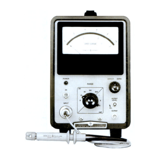
Model 428B TABLE OF CONTENTS GENERAL INFORMATION MAINTENANCE 1-1. INTRODUCTION 5-1. INTRODUCTION. 1-7. INSTRUMENT AND MANUAL IDENTIFICATION. 5-3. TEST EQUIPMENT REQUIRED. 5-5. IN-CABINET PERFORMANCE CHECKS. INSTALLATION 5-7. CLEANING OF PROBE JAWS. 2-1. UNPACKING AND MECHANICAL INSPECTION. 5-10. ELECTRICAL ZERO SET. - Page 7 Table 1-1 Specifications Table 6-1. Replaceable Parts Table 5-1. Recommended Test Equipment. LIST OF ILLUSTRATIONS Figure 1-1. Model 428B Clip-On Milliammeter Figure 5-7. Detector Phase Display. Figure 3-1. Measurement Procedures Figure 5-9. Detailed Troubleshooting Tree. Figure 3-2. Polarity of Current.
-
Page 8: Table 1-1 Specifications
Large Aperture Probe Probe Induced Voltage: -hp- Model 3529A Magnetometer Probe Less than 15 mV peak (worst case at 20 kHz and -hp- Model 11035A Output Cable harmonics). -hp- Model 10110A Output Adapter Output: Dimensions: Variable linear output level with switch position... -
Page 9: General Information
-hp- Model 3528A Large Aperture (2-1/2 inch probe head). 1-1. INTRODUCTION b. -hp- Model 3529A Magnetometer (1 1-2. The -hp- Model 428B Clip-On Milliammeter measures gauss = 1 amp). the magnetic field, which exists around the wire carrying dc c. -hp- Model C11-3529A Magnetometer current. -
Page 10: Installation
Model 428B SECTION II INSTALLATION 2-12. To operate from a 230 volt source, the 115-230 2-1. UNPACKING AND MECHANICAL INSPECTION. switch on the rear apron must be flipped to 230. First 2-2. Inspect instrument for signs of damage incurred in turn the instrument off and pull the power cable from the shipment. -
Page 11: Figure 3-1. Measurement Procedures
Model 428B Figure 3-1. Measurement Procedures... -
Page 12: Operating Instructions
The numbers are scribed Such fields may exist in the vicinity of open core with a vibrating pen. Not very HP). If a probe has to be power transformers, or large dc filter chokes, etc. -
Page 13: Magnetic Fields
Model 428B may be necessary after measuring current on the 3-19. Magnetic Fields. 1 thru 10 AMP RANGE. 3-20. If the jaws of the probe are incompletely closed, 3-32. Normally, it takes about 10 seconds to degauss the magnetic shielding and the magnetic circuit will have the probe when using the above method (see an air gap. -
Page 14: Increasing The Absolute Sensitivity
To measure current through a resistor, lift one lead and d. Zero the recorder. install a series loop, clip the 428B probe around the loop and e. Adjust the 428B ZERO control for full-scale on measure current through the resistor. As an alternative, an the 428B meter. -
Page 15: Figure 4-1. Block Diagram
Model 428B Figure 4-1. Block Diagram... -
Page 16: Theory Of Operation
SECTION IV THEORY OF OPERATION 4-1. INTRODUCTION. 4-2. This section describes the overall operation of the Model 428B, the operating principle of the current probe and the function of the different circuits of the instrument. 4-3. THEORY OF OPERATION. 4-4. The simplified block diagram of Figure 4-2 shows the basic operation of the Model 428B Clip-ON Milliammeter. -
Page 17: Figure 4-3. Magnetic Mechanical Analogy
(c). signal, driving the small cores in and out of saturation 4-17. The four coils in the 428B probe head serve 3 twice per cycle or once for each peak (positive or purposes: (a) To saturate the cores, a result of the 20 kHz negative) of the input current.(See Figure 4-6) The only... -
Page 18: 20 Khz Oscillator
Model 428B wire that is clamped in the probe jaws. (c) To conduct the signal passes through a voltage divider SI B, which dc feedback current that tends to annul the energizing dc keeps the loop gain constant for all current ranges by current from the wire being measured. -
Page 19: Dc Amplifier
Model 428B 4-43. NEGATIVE FEEDBACK CURRENT CIRCUIT. 4-35. In summary then, C and D are alternately grounded, and the polarity of the signal across T2 changes as C and D are switched to produce an output wherein the polarity 4-44. The negative feedback current path is shown in is dependent on the phase of the input. -
Page 20: Table 5-1. Recommended Test Equipment
-hp- Model 130C 100 mV/cm ± 3% AC Overload 200µV/cm Oscilloscope Troubleshooting Resistor 50 Ohms ± 1% Frequency Response -hp- Part No. 0698-3128 AC Overload 0698-8155 DC Voltmeter ± .25% at 730 mV Output Calibration -hp- Model 3430A 3469B DC Digital Voltmeter... -
Page 21: Maintenance
During the in-cabinet performance checks, the Model 428B should be connected to the ac line through a e. Set RANGE switch (4) to 1 mA. variable voltage device so that line voltage may be varied f. Zero-set the 428B with the ZERO (5) control. -
Page 22: Range Check
Zero the 428B on the 1 mA range. 5-13. RANGE CHECK. b. Switch the 428B to the 100 mA range. Switch the 5-14. Figure 5-3 illustrates the test arrangement meter calibrator to the 10 mA range and adjust for recommended. -
Page 23: Ac Overload
Model 428B f. With the 428B on the 1 mA Range check for a 5-21. AC OVERLOAD. maximum of 15 m V reading on the AC Voltmeter. 5-22. An oscillator or function generator, a 50 ohm g. Switch the 428B to the 3 mA range. Check for a maximum of 5 m V reading on the AC Voltmeter. -
Page 24: Alignment
5-45. Set an ac voltmeter to the 1 volt range and the feedback wire and the pin on the circuit board to connect it to Test Point 3 (Pin 7, V2) of the 428B. Clip which it normally connects. Connect the horizontal the 428B probe around a wire which is carrying 35 mA input of an oscilloscope to TP4 (Pin 7, V5). -
Page 25: Preliminary Adjustment
Point 3 (Pin 7 of V2). 5-55. Drive Balance Adjustment. 5-56. With the 428B set to the 1 mA range, and with no Continue to alternate Steps d and e until the input to the current probe, set R98 for a minimum ac adjustment cannot be further refined. -
Page 26: Troubleshooting
This procedure, in combination with the adjustment, calibration, and performance checks 5-66. Power Supply Check. should be adequate to repair most 428B's. 5-67. To test the power supply: 5-62. In any case where the front panel troubleshooting does not lead to the problem, it will be necessary to a. Measure +272 ±6 Vdc between Test Point 5 and... -
Page 27: Figure 5-9. Detailed Troubleshooting Tree
Model 428B Figure 5-9. Detailed Troubleshooting Tree. -
Page 28: Oscillator - Buffer Amp. Check
Test Point 2 (installed for previous checks). Disconnect shown at this point of the schematic diagram. If these the probe from the 428B front panel. Set the 428B to the waveforms are not comparable, check the waveform at 300 mA range. Zero the 428B with the front panel ZERO Test Point 7 and follow the Troubleshooting Tree. - Page 29 Model 428B...
-
Page 30: Replaceable Parts
6-5. To obtain replacement parts, address description, -hp- part number of each part, together with order or inquiry to your local Hewlett-Packard Field any applicable notes, and provides the following: Office. (See Appendix C for list of office locations.) Identify parts by their Hewlett-Packard part a. -
Page 31: Table 6-1. Replaceable Parts
Model 428B Table 6-1. Replaceable Parts REFERENCE -hp- DESCRIPTION MFR. MFR. PART NO. DESIGNATOR PART NO. A1, A2 428B-26A Assembly: resistor ww -hp A1 includes R3 thru R6 A2 includes R7 thru R 10 428B-268 Assembly: resistor ww, includes R2, Rll -hp... - Page 32 Model 428B Table 6-1. Replaceable Parts (Cont'd) REFERENCE -hp- DESCRIPTION MFR. MFR. PART NO. DESIGNATOR PART NO. 2110-0202 Fuse: .5 AT 250 V (for 230 V operation) 71400 MDL-1/12 2110-0312 Fuse: 1 AT 250 V (for 115 V operation) 71400...
- Page 33 Model 428B Table 6-1. Replaceable Parts (Cont'd) REFERENCE -hp- DESCRIPTION MFR. MFR. PART NO. DESIGNATOR PART NO. 0757-1039 R: fxd flm 45 ohms 1% 1/4 W 14674 C5 T-0 0757-1047 R: fxd flm 90 ohms 1% 1/4 W 19701 MF52C T-0 2100-0328 R: var 500 ohms 10% ww 1.5 W...
- Page 34 Model 428B Table 6-1. Replaceable Parts (Cont'd) REFERENCE -hp- DESCRIPTION MFR. MFR. PART NO. DESIGNATOR PART NO. 9100-1486 Transformer: head drive -hp 9100-3228 Transformer: power -hp V1, V2 1923-0017 Tube: electron 6AH6 33173 6AH6 V3, V4 Not assigned 1923-0017 Tube: electron 6AH6...
-
Page 35: Figure 6-1. Parts Breakdown, Current Probe
Model 428B Figure 6-1. Parts Breakdown, current probe. -
Page 36: Circuit Diagrams
7-2. This section contains the circuit diagrams necessary shown in the schematic diagrams. These diagrams are for the operation and maintenance of the Model 428B used to develop an understanding of the detailed theory Clip-on DC Milliammeter. Included are a block diagram, of operation of each assembly and as an aid in isolating schematics and component location diagrams. -
Page 37: Figure 7-1. Block Diagram
Model 428B Figure 7-1. Block Diagram. -
Page 38: Figure 7-2. Component Locator For Circuit Board Part
Model 428B Figure 7-2. Component Locator For Circuit Board Part No. 00428-66501 Figure 7-4 Rear Panel Component Locator. Figure 7-3. Front Panel Component Locator. -
Page 39: Figure 7-5. Power Supply
Model 428B Figure 7-5. Power Supply. -
Page 40: Figure 7-6. Block Diagram
Model 428B Figure 7-6. Block Diagram. -
Page 41: Figure 7-7. Component Locator For Circuit Board Part
Model 428B Figure 7-7. Component Locator for Circuit Board Part No. 00428-66501 Figure 7-8. Front Panel Component Locator. Figure 7-9 Rear Panel Component Locator. -
Page 42: Figure 7-10. Metering Circuit
Model 428B Figure 7-10. Metering Circuit (Note: This schematic has been chopped and resectioned to reduce the 11x30 page to better fit on 8½x11 paper) -
Page 43: Manual Backdating Changes
A-1. The changes which appear in this Appendix make A-2. Schematic diagrams, photographs, and a parts this manual applicable to those 428B Clip-on DC list for the earlier instruments have been included in Milliammeters which bear serial number prefixes of this Appendix. -
Page 44: Figure A-1. 428B Side Views
Model 428B Figure A-1. 428B Side Views. -
Page 45: Figure A-2 Backdating Schematics For 428B
Model 428B Figure A-2 Backdating Schematics for 428B... -
Page 46: Figure A-3 Backdating Schematics For 428B
Model 428B Figure A-3 Backdating Schematics for 428B... - Page 47 Model 428B Circuit Reference Stock No. Description # Reference 0150-0012 fxd cer, 10K pf +20%, 1000 vdcw A1, 2 428B-26A Assembly: ww resistor, 0180-0058 fxd, elect, 50µf -10% + 100%, 25 vdcw A1 includes, R3 thru R6 0180-0104 fxd, elect, 200 µf 15 vdcw...
- Page 48 Model 428B Circuit 2100-0002 var, ww, 50 ohms ±10%, 2 W Stock No. Description # Reference-hp- 0687-1001 fxd, comp, 10 ohms ±10%, 1/2 W 0693-1041 fxd, comp, 100K ohms ±10%, 2 W 0727-0198 fxd, dep c, 66K ohms ±1%, 1/2 W 0690-1241 fxd, comp, 120K*ohms ±10% 1 W...
- Page 49 Model 428B Circuit -hp- Stock Circuit Description# -hp- Stock No. Description# Reference Reference R110 0727 -0218 fxd, dep c, 180K ohms ±1%, 1/2 W 428B-75E Assembly: resistor board "E" includes 428B -19A Assembly: range switch, includes, C27 thru C29 R47 thru R52...
- Page 50 5-28a. Connect an electronic dc voltmeter to test 3-29). point 5 (Pin 1, V9) of the 428B. The voltage at this ►Page 5-5, Paragraph 5-58. Remove Steps a and b. point should be 272 ± 6 V; if not, adjust R 109 for Re-letter Steps c to f to read a to d respectively.
- Page 51 ("starred") components marked wit an the· Output Level jack. asterisk may not even be present. b. Switch the 428B and the meter calibrator to Page 7-3, figure 7-5. TP5 is connected to pin 1 of V9. the 100 mA range. Connect a test lead Reverse F1 and F2.
- Page 52 Model 428B 0042890003 PRINTED IN U.S.A.