Advertisement
Quick Links
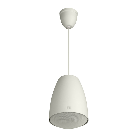
PENDANT SPEAKER
Thank you for purchasing TOA's Pendant Speaker.
Please carefully follow the instructions in this manual to ensure long, trouble-free use
of your equipment.
TABLE OF CONTENTS
1. SAFETY PRECAUTIONS ........................... 1
AND FEATURES ......................................... 2
3. IMPEDANCE CHANGE .............................. 2
4. INSTALLATION .......................................... 3
1. SAFETY PRECAUTIONS
• Before installation or use, be sure to carefully read all the instructions in this section for correct and safe
operation.
• Be sure to follow all the precautionary instructions in this section, which contain important warnings and/or
cautions regarding safety.
• After reading, keep this manual handy for future reference.
WARNING
Indicates a potentially hazardous situation which,
if mishandled, could result in death or serious
personal injury.
When Installing the Unit
• Refer all installation work to the dealer from whom
the speaker was purchased. Installation work
requires extensive technical knowledge and
experience. The speaker may fall off if incorrectly
installed, resulting in possible personal injury.
• Install the speaker only in a location that can
structurally support the full weight of the unit and
mounting bracket. Doing otherwise may result in
the speaker falling down and causing personal
Traceability Information for Europe (EMC directive 2004/108/EC)
Manufacturer:
TOA Corporation
7-2-1, Minatojima Nakamachi, Chuo-ku, Kobe, Hyogo,
Japan
INSTRUCTION MANUAL
PE-154BS
5. DIMENSIONAL DIAGRAM ......................... 4
6. WIRING DIAGRAM ...................................... 4
7. FREQUENCY RESPONSE (1 W, 4 m) ....... 5
8. SPECIFICATIONS ...................................... 5
injury and/or property damage.
• Since the unit is designed for in-door use, do not
install it outdoors. If installed outdoors, the aging of
parts causes the unit to fall off, resulting in personal
injury. Also, when it gets wet with rain, there is a
danger of electric shock.
• Do not use other methods than specified to install
the speaker. Extreme force is applied to the
speaker and the speaker could fall off, possibly
resulting in personal injuries.
• Use screws that are appropriate for the ceiling's
material and structure. Failure to do so may cause
the speaker to fall, resulting in material damage
and possible personal injury.
• Ensure that all screws are securely tightened. If
they are loose after installation, the speaker could
fall down, possibly resulting in personal injury.
Authorized representative:
TOA Electronics Europe GmbH
Suederstrasse 282, 20537 Hamburg,
Germany
Advertisement

Related Manuals for Toa PE-154BS


Summary of Contents for Toa PE-154BS
-
Page 1: Table Of Contents
INSTRUCTION MANUAL PENDANT SPEAKER PE-154BS Thank you for purchasing TOA's Pendant Speaker. Please carefully follow the instructions in this manual to ensure long, trouble-free use of your equipment. TABLE OF CONTENTS 1. SAFETY PRECAUTIONS ......1 5. DIMENSIONAL DIAGRAM ......4 2. -
Page 2: General Description And Features
The speaker is driven on high-impedance (100 V and 70 V) line, and its input power (impedance) can be easily switched. Note Never dismantle the PE-154BS in any way even for repainting reason. Since the PE-154BS is certified in the form of complete assembly by the above-mentioned standards, it does not meet these standards if dismantled. -
Page 3: Installation
4. INSTALLATION Step 1. Secure the ceiling bracket to the ceiling with Step 5. Put the mounting hanger onto the ceiling 4 screws. bracket's hook. Pull the cable through the cable gland in the bracket. Ceiling bracket (accessory) Cable gland Ceiling Tapping screw 4 x 16 (accessory) Note... -
Page 4: Dimensional Diagram
[When making a bridge connection] Ceiling bracket Punch out the knockout in the ceiling bracket and attach the cable gland (option) there. Notes Knockout • To punch out the knockout, apply a force to it in the direction of the arrow as shown at right. In this case, Cable gland take care not to bend the metal rim along the knockout. -
Page 5: Frequency Response (1 W, 4 M)
7. FREQUENCY RESPONSE (1 W, 4 m) [dB] 10 k 20 k [Hz] Frequency-SPL 8. SPECIFICATIONS Standards Certified to the European Standard EN 54-24: 2008 EN 54-24: 2008 Loudspeaker for voice alarm systems 0359-CPD-0105 for fire detection and fire alarm systems 0359 Certification No. - Page 8 URL: http://www.toa.jp/ 533-06-238-20...