Motorola CP150 User Manual
Commercial series
Hide thumbs
Also See for CP150:
- Service manual (252 pages) ,
- Basic service manual (68 pages) ,
- Specifications (2 pages)

Related Manuals for Motorola CP150


Summary of Contents for Motorola CP150
- Page 1 CP150 ™ /CP200 ™ Commercial Series Two-Way Radio User Guide Manuel de l'utilisateur de la radio bidirectionnelle...
-
Page 3: Table Of Contents
Parts of the Radio ....11 CP150/CP200 Models ... . . 11 On/Off/Volume Knob . -
Page 4: Computer Software Copyrights
Motorola. Furthermore, the purchase of Motorola products shall not be deemed to grant either directly or by implication, estoppel, or otherwise, any license under the copyrights, patents or patent... -
Page 5: Safety And Warranty
Charge the battery before use to ensure optimum capacity and performance. The battery was designed specifically to be used with a Motorola charger. Charging in non- Motorola equipment may lead to battery damage and void the battery warranty. Note: When charging a battery attached to a radio, turn the radio off to ensure a full charge. -
Page 6: Limited Warranty
CP150/CP200 Portable Units Product Accessories Motorola, at its option, will at no charge either repair the Product (with new or reconditioned parts), replace it (with a new or reconditioned Product), or refund the purchase price of the... - Page 7 This warranty sets forth the full extent of MOTOROLA's responsibilities regarding the Product. Repair, replacement or refund of the purchase price, at MOTOROLA’s option, is the exclusive remedy. THIS WARRANTY IS GIVEN IN LIEU OF ALL OTHER EXPRESS WARRANTIES. IMPLIED WARRANTIES,...
- Page 8 Product. Normal and customary wear and tear. VI. PATENT AND SOFTWARE PROVISIONS: MOTOROLA will defend, at its own expense, any suit brought against the end user purchaser to the extent that it is based on a claim that the...
- Page 9 MOTOROLA will have sole control of the defense of such suit and all negotiations for its settlement or compromise; and should the Product or parts become, or in MOTOROLA’s opinion be likely to become, the subject of a claim of infringement of a...
- Page 10 Notes: English...
-
Page 11: Introduction
To ensure coordinated use by multiple users, each radio user must monitor the channel or repeater before transmitting to verify that the system is not currently busy. CP150™/CP200™ RADIO FEATURES Radio Wide Features • 4 or 16 Channels •... - Page 12 Notes: English...
-
Page 13: Radio Overview
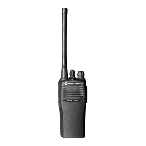
RADIO OVERVIEW Push-to-Talk (PTT) Button Side Button 1 (programmable) Side Button 2 (programmable) PARTS OF THE RADIO CP150/CP200 Models On/Off/Volume Knob Channel Selector Knob LED Indicator Microphone Accessory Connector with a Dust Cover English... -
Page 14: On/Off/Volume Knob
On/Off/Volume Knob Turns the radio on or off, and adjusts the radio’s volume. Channel Selector Knob Switches the radio to different channels. Push-to-Talk (PTT) Button Press and hold down this button to talk (transmit); release it to listen. Microphone When sending a message, hold the microphone 1 to 2 inches (2.5 to 5 cm) away from your mouth, and speak clearly into it. -
Page 15: Programmable Buttons
Battery Charge Status You can check battery charge status if your dealer has preprogrammed one of the programmable buttons. Hold down the preprogrammed Battery Indicator button. The charge status is shown by the color of the radio’s LED indicator. Battery Level Indicator Good... - Page 16 Feature Battery Indicator A long press of the Monitor button Sticky Monitor/ initiates. A short press of the Monitor Monitor button cancels. Volume Set Sounds a tone for adjusting the radio’s volume level. Voice Operated Transmission Toggle VOX on and off. (VOX) Toggles your radio’s transmit power †...
-
Page 17: Indicator Tones
Feature Short Press/Long Press Scan Starts or stops the Scan operation. Nuisance Deletes a nuisance channel while Channel Delete scanning. INDICATOR TONES High pitched tone Low pitched tone Self Test Pass Tone Self Test Fail Tone Positive Indicator Tone Negative Indicator Tone Hold Down Page —... -
Page 18: Improved Audio Features
IMPROVED AUDIO FEATURES Companding Companding is a feature that allows further improvement of voice quality. It compresses your voice at transmission, and expands it when receiving while simultaneously reducing extraneous noise. However, to enjoy this benefit, all transmitting and receiving radios must have this feature activated. -
Page 19: Getting Started
GETTING STARTED BATTERY INFORMATION Charging Your Battery If a battery is new, or its charge level is very low, you will need to charge it before you can use it. When the battery level is low and the radio is in transmit mode you will see the LED indicator flash red. -
Page 20: Desktop Chargers
14 to 16 hours prior to initial use Successful charger for best performance. power-up. Battery unchargeable or not A list of Motorola authorized batteries and making proper contact. battery chargers appears on page 35. The Battery is in Rapid charge listed chargers will charge only Motorola mode. -
Page 21: Slow Charger
Slow Charger Turn the radio off. Place the battery, with or without the radio, in the charger pocket. • The charger LED indicates the charging progress. LED color Status No LED Indication Battery inserted incorrectly or battery not detected. Steady Red Battery is in over night charge mode. -
Page 22: Accessory Information
ACCESSORY INFORMATION Attaching the Battery Align the battery to the battery rails on the back of the radio (approximately 1/2 in. from the top of the radio.) Press the battery firmly to the radio and slide the battery upward until the latch snaps into place. Slide the battery latch, located on radio bottom, into the lock position. -
Page 23: Attaching The Antenna
Attaching the Antenna Removing the Antenna Turn the antenna clockwise to attach it. Turn the antenna counter-clockwise to remove English... -
Page 24: Attaching The Belt Clip
Attaching the Belt Clip Align the grooves of the belt clip with those of the battery. Press the belt clip downward until you hear a click. English Removing the Belt Clip Belt Clip Tab Use a key to press the belt clip tab away from the battery to unlock the belt clip. -
Page 25: Turning The Radio On Or Off
TURNING THE RADIO ON OR OFF Turn the On/Off/ Turn the On/Off/ Volume Control Volume Control knob knob clockwise. If counter-clockwise until power-up is you hear a click. successful, you will hear the Self-Test Pass Tone ) and see the LED flash green. -
Page 26: Receiving
RECEIVING Turn your radio on. Adjust the radio’s volume (see page 23). Switch to the desired channel. To respond, hold the radio in a vertical position, press the PTT, and talk at a distance of about 1 to 2 inches (2.5 to 5 cm) from the microphone. MONITORING It is important to monitor traffic before transmitting to ensure that you do not “talk... -
Page 27: Vox Operation
VOX OPERATION When hands-free operation is desired, your radio can be activated by voice alone using the VOX feature when you speak through an accessory that is connected to your radio. Connecting a VOX Headset Turn off your radio. Connect the VOX accessory to your radio and turn the radio on. -
Page 28: Non-Vox Headset With In-Line Ptt
To disable the headset sidetone, turn off your radio and turn the radio on again. Non-VOX Headset with In-Line PTT Turn off your radio. Connect the non-VOX accessory to your radio. Press and hold the In-line PTT on your headset. Turn the radio on and release the PTT once the radio has completed start-up. -
Page 29: Setting The Power Level
SETTING THE POWER LEVEL (Available for 4W and 5W models only) Each channel in your radio has a predefined transmit power level that can be changed. • High power allows you to reach a radio that is farther away. • Low power conserves the battery’s charge. - Page 30 Notes: English...
-
Page 31: Radio Calls
RADIO CALLS RECEIVING A SELECTIVE CALL (Available for 4W and 5W models only) When you receive a Selective Call: • The LED indicator flashes yellow, if pro- grammed by your dealer. • You hear two high pitched tones. To acknowledge the call, press and release the PTT button. - Page 32 Notes: English...
-
Page 33: Scan
SCAN Your radio is equipped with the Scan feature, which allows you to monitor multiple channels for voice activity. The radio will stop on a channel when it detects activity on it. Your radio automatically switches to a channel within the scan list when it detects activity. The LED indicator blinks green during a scan operation and stops blinking when the radio switches to a channel. -
Page 34: Deleting A Nuisance Channel
DELETING A NUISANCE CHANNEL Note: Your dealer must preprogram a button to Nuisance Delete (see page 14) to access this feature. If a channel continually generates unwanted calls or noise (a “nuisance” channel), you can temporarily remove it from the scan list: While the radio is on the Nuisance Channel, press the preprogrammed Nuisance Channel Delete button until you hear a tone. -
Page 35: Prioritizing A Scan List Member
PRIORITIZING A SCAN LIST MEMBER You may want your radio to scan a specific channel more frequently for calls. Your dealer can prioritize scan list members for you. Check with your dealer for details. Priority Channel Scanning Sequence None specified Ch1 Ch2 Ch3 Ch4 ...Ch1 Channel 2... - Page 36 Notes: English...
-
Page 38: Headsets
HEADSETS RLN5411 Ultra-Lite Breeze Behind the Head Headset PMMN4001 Ultra-Lite Earset with Mic and PTT HMN9013 Lightweight Headset w/o In-line PTT RMN4016 Lightweight Headset with In-line PTT RLN5238 Lightweight Headset with In-line PTT, NFL Style HMN9021 Medium Weight Over the Head Dual Muff Headset HMN9022 Medium Weight Behind the Head... -
Page 39: Remote Speaker Microphones
RLN5198 Earpiece with Microphone & PTT Combined, 2-Wire w/Low Noise Kit NTscn(83)-7.3(71 (Beige))]TJ-8.1429 -1.6241 TD0 Tc-0.0524 Tw[(BDN67)-7.9(2)-0.4(0)-3797.4(F)-5.5(le)22.2(xib)22.2(l)-3cne E HMN9036 Earbud with Microphone & PTT Cmbined, 2-Wire (Black) HLN9132 Earbud Single Wire Receiv (Black) NT8370 Extrem NT(8371)-3857.5(L)-7.9(o)14.6(w Noise)-7.9( K)5.3(i)-3cnt RLN4760 Small Custom Clear Earp Right Ear (for use with low noise kit NTsc3(83)-7.6(71))]TJ-8.1429 -1.6316 TD0.001 Tc-0.0008 Tw[(RLN)-6.3(4763)-3909.2(Small Custom Clear E REMOTE SPEAKER MICROPHONES... -
Page 40: Antennas
0180358B38 Ring Push-to-Talk Switch (for use with ear microphone systems BDN6646 & BDN6706) 0180300E83 Body Switch Push-to-Talk (for use with ear microphone systems BDN6646 & BDN6706) 0180300E25 Ear Guard with Adjustable Loop 0180358B32 Ear Holder, Black, Small 0180358B33 Ear Holder, Black, Medium 0180358B34 Ear Holder, Black, Large 0180358B35... - Page 41 Sufficient Flashing Red None Very Low †Available for 4W and 5W models only. ™ ™ CP150 /CP200 Quick Reference Card On/Off/Volume Knob Channel Selector Knob NOTE: Enter the functions for your radio’s two programmable buttons in the boxes provided above.
- Page 42 Turning On the Radio • Turn On/Off/Volume Control knob clockwise. If the radio successfully powers up, you will hear the Self Test Pass tone and see the LED light green. If the radio fails to power up, you will hear the Self Test Fail tone.
- Page 44 © Motorola, Inc. 2002, 2003. All rights reserved. Printed in U.S.A. MOTOROLA, le logotype au M stylisé et Radius sont enregistrés auprès du Bureau des marques et brevets des États-Unis. Tous les autres noms de produits et de services sont la propriété de leurs titulaires respectifs.