
Related Manuals for GBC BOILER 1-4 K


Summary of Contents for GBC BOILER 1-4 K
- Page 1 INSTRUCTION MANUAL BOILER 1-4 K Range Ø 23 / 108 mm (0,90” — 4,25”) G.B.C. Industrial Tools S.p.A. Via Sandro Pertini 41/43 – 25046 Cazzago San Martino (Bs) – Italia – Tel. + 39 030 7451154 – Fax. + 39 030 73 56 629...
- Page 2 BOILER 1”-4” K Istruzioni originali—rev.2011—in accordo al 1.7.4 della direttiva macchine 2006/42/CE INDEX Presentation of the company and introduction to the Instruction Manual Warranty General Clauses Intended Use Of The Machine Technical Data Machine Configuration Models Machine Standard Equipment Optional Equipment Safety Prescriptions Transport recommendations Machine Stability...
- Page 3 BOILER 1”-4” K Istruzioni originali—rev.2011—in accordo al 1.7.4 della direttiva macchine 2006/42/CE G.B.C. Industrial Tools S.p.A. is known worldwide for the quality of the machines and accesso- ries for pipe cutting and beveling procedures of any sort and plate beveling machines.. The Headquarters are located in Cazzago San Martino (BS) where are currently operating the General Management, the sales department, as well as the main workshop and the shipping de- partment.
- Page 4 BOILER 1”-4” K Istruzioni originali—rev.2011—in accordo al 1.7.4 della direttiva macchine 2006/42/CE G.B.C. Industrial Tools S.p.a. guarantees the reliability of the machine and its conformity to the specifications herewith reported. The warranty covers the machine in its whole for a time period of one year from the shipment date (ref.
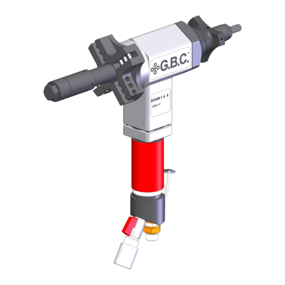
- Page 5 BOILER 1”-4” K Istruzioni originali—rev.2011—in accordo al 1.7.4 della direttiva macchine 2006/42/CE The machine shown in the drawing is conceived for beveling pipe ends and to prep the for the subsequent welding process. It works gripped into the ID of the pipe. The bevel is obtained by bevelling tools of various shape and materials, de-...
-
Page 6: Technical Data
BOILER 1”-4” K Istruzioni originali—rev.2011—in accordo al 1.7.4 della direttiva macchine 2006/42/CE TECHNICAL DATA PNEUMATIC ELECTRIC BATTERY 23 - 108 23 - 108 23 - 108 ID Locking Range mm (inches) (0.9-4.25) (0.9-4.25) (0.9-4.25) Idle Speed gg/min (Rpm) 27 (6 bar) Chuck Max Torque 82 (8 bar) Stroke... - Page 7 BOILER 1”-4” K Istruzioni originali—rev.2011—in accordo al 1.7.4 della direttiva macchine 2006/42/CE BOILER 1”-4” K “ E” BOILER 1”-4” K BOILER 1”-4” K “ With Autolock” BOILER 1”-4” K Ratchet G.B.C. Industrial Tools S.p.A. Via Sandro Pertini 41/43 – 25046 Cazzago San Martino (Bs) – Italia – Tel. + 39 030 7451154 – Fax. + 39 030 73 56 629...
-
Page 8: Service Tools
• 14-17 mm wrench • Storage Case • Instruction Manual And Exploded Drawings Boiler 1-4 K Service Tools Case Instruction Manual And Exploded Drawings G.B.C. Industrial Tools S.p.A. Via Sandro Pertini 41/43 – 25046 Cazzago San Martino (Bs) – Italia – Tel. + 39 030 7451154 – Fax. + 39 030 73 56 629... - Page 9 BOILER 1”-4” K Istruzioni originali—rev.2011—in accordo al 1.7.4 della direttiva macchine 2006/42/CE INTERCHANGEABLE ELBOW SHAFTS FOR CURVED ID PIPES FROM 46mm to 103mm. G.B.C. Industrial Tools S.p.A. Via Sandro Pertini 41/43 – 25046 Cazzago San Martino (Bs) – Italia – Tel. + 39 030 7451154 – Fax. + 39 030 73 56 629...
- Page 10 BOILER 1”-4” K Istruzioni originali—rev.2011—in accordo al 1.7.4 della direttiva macchine 2006/42/CE G.B.C. Industrial Tools S.p.A. designs and assembles its machines in strict compliance with the safety regulations provided by the applicable EC directives and by the Italian laws regulat- ing this matter.
- Page 11 BOILER 1”-4” K Istruzioni originali—rev.2011—in accordo al 1.7.4 della direttiva macchine 2006/42/CE Using properly the PPE entails the only risks to be generated by the user’s system and not by in born defects of our machines. 1 Always wear protective gloves and eyewear. 2 Always disconnect the machine from the power source during the setup.
- Page 12 BOILER 1”-4” K Istruzioni originali—rev.2011—in accordo al 1.7.4 della direttiva macchine 2006/42/CE Considering the mass of the machine no particular problem has been detected in regard to the operator safety. By always using both hands for operating the machine, the operator is unable to reach the bevelling tools as the unit would suddenly stop –...
- Page 13 BOILER 1”-4” K Istruzioni originali—rev.2011—in accordo al 1.7.4 della direttiva macchine 2006/42/CE Ensure the vane expansion nut is not abutted, then unscrew the vane abutment cap, and the vane abutment bush. Remove the locking jaws you want to replace WARNINIG : DO NOT MOVE THE EXPANSION SHAFT! The expansion shaft can be moved by the vane expansion nut after having replaced the locking jaws.
- Page 14 BOILER 1”-4” K Istruzioni originali—rev.2011—in accordo al 1.7.4 della direttiva macchine 2006/42/CE Select the LOCKING JAWS according to the diameter of the pipe and install them on the expansion shaft as shown in the picture. While holding the three LOCKING JAWS you have just mounted, unscrew the VANE EXPANSION NUT in order to let them enter their seat.
- Page 15 BOILER 1”-4” K Istruzioni originali—rev.2011—in accordo al 1.7.4 della direttiva macchine 2006/42/CE Screw back on clockwise the vane expansion bush all way down and then the vane expansion nut. While keeping the machine in axis with the pipe, insert the SHAFT in the pipe (about 15-20mm) Firmly screw clockwise the VANE EXPANSION NUT.
- Page 16 BOILER 1”-4” K Istruzioni originali—rev.2011—in accordo al 1.7.4 della direttiva macchine 2006/42/CE Select the BEVELLING TOOL in regard to the bevel you need to perform and insert it on the CHUCK locking it with the two grub screws by using the Allen key . You will want to use two paired cutting tools and one facing tools when required.
- Page 17 BOILER 1”-4” K Istruzioni originali—rev.2011—in accordo al 1.7.4 della direttiva macchine 2006/42/CE Connect the machine to the air hose. Press the button lever upwards to actuate the machine. WARNING! You will need to apply a constant pressure on the lever. G.B.C.
- Page 18 BOILER 1”-4” K Istruzioni originali—rev.2011—in accordo al 1.7.4 della direttiva macchine 2006/42/CE The machine feeding is actuated by turning the hand wheel clockwise as shown in the picture. Maintain a constant and continuous action to obtain a uniform feeding. The motor will automatically stop by releasing the lever. G.B.C.
- Page 19 BOILER 1”-4” K Istruzioni originali—rev.2011—in accordo al 1.7.4 della direttiva macchine 2006/42/CE WARNING! DURING THE OPERTIONS PAY ATTENTION NOT TO TOUCH THE LOCKING JAWS WITH THE TOOLS AS THESE MAY GET DAMAGED. REMOVING THE MACHINE FROM THE PIPE: 1. Unscrew the vane expansion nut using the wrench supplied with the machine. 2.
- Page 20 BOILER 1”-4” K Istruzioni originali—rev.2011—in accordo al 1.7.4 della direttiva macchine 2006/42/CE Unscrew the vane abutment cap and the vane abutment bush counter clockwise. Remove the locking jaws. G.B.C. Industrial Tools S.p.A. Via Sandro Pertini 41/43 – 25046 Cazzago San Martino (Bs) – Italia – Tel. + 39 030 7451154 – Fax. + 39 030 73 56 629...
- Page 21 BOILER 1”-4” K Istruzioni originali—rev.2011—in accordo al 1.7.4 della direttiva macchine 2006/42/CE Screw the vane expansion nut until it ‘s butted to the machine. By using long nose pliers rotate clockwise the expansion shaft until it comes out. G.B.C. Industrial Tools S.p.A. Via Sandro Pertini 41/43 –...
- Page 22 BOILER 1”-4” K Istruzioni originali—rev.2011—in accordo al 1.7.4 della direttiva macchine 2006/42/CE Remove the vane expansion nut. Remove the grub screw cap and the grub screw from the cover case in order to release the guiding shaft. G.B.C. Industrial Tools S.p.A. Via Sandro Pertini 41/43 –...
- Page 23 BOILER 1”-4” K Istruzioni originali—rev.2011—in accordo al 1.7.4 della direttiva macchine 2006/42/CE Remove the shaft by rotating the hand wheel clockwise. Take the guiding shaft from the reduced shaft kit and mark the groove of the lap joint as well as the far end of the shaft as shown in the picture.
- Page 24 BOILER 1”-4” K Istruzioni originali—rev.2011—in accordo al 1.7.4 della direttiva macchine 2006/42/CE Insert the expansion shaft in the machine and align it’s lap joint with the hole of the cover case where you will want to insert the two grub screws previously removed. Rotate the hand wheel to get the shaft in the machine.
- Page 25 BOILER 1”-4” K Istruzioni originali—rev.2011—in accordo al 1.7.4 della direttiva macchine 2006/42/CE Reassemble the grub screw and the grub screw cover locking them tight. Screw in all way down the vane expansion nut. G.B.C. Industrial Tools S.p.A. Via Sandro Pertini 41/43 – 25046 Cazzago San Martino (Bs) – Italia – Tel. + 39 030 7451154 – Fax. + 39 030 73 56 629...
- Page 26 BOILER 1”-4” K Istruzioni originali—rev.2011—in accordo al 1.7.4 della direttiva macchine 2006/42/CE Insert the reduced expansion shaft. By using a inserted in the vane expansion nut, screw the vane expansion shaft until it’s positioned 2mm inside from the end of the reduced guiding shaft as shown in the picture. G.B.C.
- Page 27 BOILER 1”-4” K Istruzioni originali—rev.2011—in accordo al 1.7.4 della direttiva macchine 2006/42/CE Select the correct locking jaws according to the ID of the pipe you need to work and place them in the shaft as shown in the picture. While holding the three LOCKING JAWS you have just mounted, unscrew the VANE EXPANSION NUT in order to let them enter their seat.
- Page 28 BOILER 1”-4” K Istruzioni originali—rev.2011—in accordo al 1.7.4 della direttiva macchine 2006/42/CE Screw back on the vane expansion nut all the way. Rotate the shaft clockwise with long nose pliers and extract it. G.B.C. Industrial Tools S.p.A. Via Sandro Pertini 41/43 – 25046 Cazzago San Martino (Bs) – Italia – Tel. + 39 030 7451154 – Fax. + 39 030 73 56 629...
- Page 29 BOILER 1”-4” K Istruzioni originali—rev.2011—in accordo al 1.7.4 della direttiva macchine 2006/42/CE Remove the vane expansion nut. Remove the grub screw cap and the grub screw from the cover case in order to release the shaft. G.B.C. Industrial Tools S.p.A. Via Sandro Pertini 41/43 –...
- Page 30 BOILER 1”-4” K Istruzioni originali—rev.2011—in accordo al 1.7.4 della direttiva macchine 2006/42/CE Remove the shaft by rotating the hand wheel clockwise. Extract the tool abutment chuck by using the special tool not supplied with the machine. G.B.C. Industrial Tools S.p.A. Via Sandro Pertini 41/43 –...
- Page 31 BOILER 1”-4” K Istruzioni originali—rev.2011—in accordo al 1.7.4 della direttiva macchine 2006/42/CE Insert the tool abutment bush supplied with the elbow locking kit. Take the shaft from the reduced shaft kit and use a marker to mark the groove of the lap joint as well as the far end of the shaft as shown in the picture.
- Page 32 BOILER 1”-4” K Istruzioni originali—rev.2011—in accordo al 1.7.4 della direttiva macchine 2006/42/CE Insert the elbow shaft in the machine and align its lap joint with the hole of the cover case where the two grub screws should then be screwed back in. Rotate the hand wheel in order to get the shaft inside the machine.
- Page 33 BOILER 1”-4” K Istruzioni originali—rev.2011—in accordo al 1.7.4 della direttiva macchine 2006/42/CE Screw back in the grub screw and the grub screw cover locking them tight. Screw back in all way down the vane expansion nut. G.B.C. Industrial Tools S.p.A. Via Sandro Pertini 41/43 –...
- Page 34 BOILER 1”-4” K Istruzioni originali—rev.2011—in accordo al 1.7.4 della direttiva macchine 2006/42/CE Slide in the elbow shaft. Screw by using long nose pliers in the elbow shaft using a screwdriver until it extends 20mm from the head as shown in the picture . G.B.C.
- Page 35 BOILER 1”-4” K Istruzioni originali—rev.2011—in accordo al 1.7.4 della direttiva macchine 2006/42/CE Slide the selected locking jaws in the expansion shaft. Fix the cover with the special screws supplied with it. The machine is now ready to be used. G.B.C. Industrial Tools S.p.A. Via Sandro Pertini 41/43 –...
- Page 36 BOILER 1”-4” K Istruzioni originali—rev.2011—in accordo al 1.7.4 della direttiva macchine 2006/42/CE Ensure the vane expansion nut is not abutted, then unscrew the vane abutment cap and the vane abutment bush counter clockwise. Remove the locking jaws. G.B.C. Industrial Tools S.p.A. Via Sandro Pertini 41/43 –...
- Page 37 BOILER 1”-4” K Istruzioni originali—rev.2011—in accordo al 1.7.4 della direttiva macchine 2006/42/CE Screw back on the vane expansion nut all the way. Rotate the shaft clockwise with long nose pliers and extract it. G.B.C. Industrial Tools S.p.A. Via Sandro Pertini 41/43 – 25046 Cazzago San Martino (Bs) – Italia – Tel. + 39 030 7451154 – Fax. + 39 030 73 56 629...
- Page 38 BOILER 1”-4” K Istruzioni originali—rev.2011—in accordo al 1.7.4 della direttiva macchine 2006/42/CE Unscrew the vane expansion nut. In replacement of the vane expansion nut you will need to screw the counter nut, and then the pneumatic locking device as shown in the picture. G.B.C.
- Page 39 BOILER 1”-4” K Istruzioni originali—rev.2011—in accordo al 1.7.4 della direttiva macchine 2006/42/CE Screw the locking device and fix it in position with the counter nut. As shown in the picture. Unscrew the nipple and install the air connector supplied with the kit. G.B.C.
- Page 40 BOILER 1”-4” K Istruzioni originali—rev.2011—in accordo al 1.7.4 della direttiva macchine 2006/42/CE Plug the air supply tube. After having supplied the pneumatic locking device with air, move the lever downward to move the locking piston forward. G.B.C. Industrial Tools S.p.A. Via Sandro Pertini 41/43 –...
- Page 41 BOILER 1”-4” K Istruzioni originali—rev.2011—in accordo al 1.7.4 della direttiva macchine 2006/42/CE Slide the vane expansion shaft into the guiding shaft , and screw it counter-clockwise until you will obtain a gap of 0.5 ÷ 1 mm by screwing back on the vane abutment cap. G.B.C.
- Page 42 BOILER 1”-4” K Istruzioni originali—rev.2011—in accordo al 1.7.4 della direttiva macchine 2006/42/CE Select the LOCKING JAWS according to the diameter of the pipe and install them on the expansion shaft as shown in the picture. After having supplied the pneumatic locking device with air, keep the locking jaws pressed with your hand and move the lever upward to get the expansion shaft withdrawn in the machine.
- Page 43 BOILER 1”-4” K Istruzioni originali—rev.2011—in accordo al 1.7.4 della direttiva macchine 2006/42/CE Screw back on the vane abutment bush and the vane abutment cap counter clockwise. In the rear part of the locking device you shall now insert the stem and the two grub screws as shown in the pictur making sure not to move the expansion shaft.
- Page 44 BOILER 1”-4” K Istruzioni originali—rev.2011—in accordo al 1.7.4 della direttiva macchine 2006/42/CE Screw the grub screws and the knobs supplied with the locking device. G.B.C. Industrial Tools S.p.A. Via Sandro Pertini 41/43 – 25046 Cazzago San Martino (Bs) – Italia – Tel. + 39 030 7451154 – Fax. + 39 030 73 56 629...
- Page 45 BOILER 1”-4” K Istruzioni originali—rev.2011—in accordo al 1.7.4 della direttiva macchine 2006/42/CE Insert the expansion shaft in the machine and align its lap joint with the hole of the cover case where you will want to insert the two grub screws previously removed. Rotate the hand wheel to get the shaft in the machine.
- Page 46 BOILER 1”-4” K Istruzioni originali—rev.2011—in accordo al 1.7.4 della direttiva macchine 2006/42/CE Ensure the vane expansion nut is not abutted, then unscrew the vane abutment cap and the vane abutment bush counter-clockwise. Remove the locking jaws G.B.C. Industrial Tools S.p.A. Via Sandro Pertini 41/43 –...
- Page 47 BOILER 1”-4” K Istruzioni originali—rev.2011—in accordo al 1.7.4 della direttiva macchine 2006/42/CE Screw back on the vane expansion nut all the way. Rotate the shaft clockwise with long nose pliers and extract it. G.B.C. Industrial Tools S.p.A. Via Sandro Pertini 41/43 – 25046 Cazzago San Martino (Bs) – Italia – Tel. + 39 030 7451154 – Fax. + 39 030 73 56 629...
- Page 48 BOILER 1”-4” K Istruzioni originali—rev.2011—in accordo al 1.7.4 della direttiva macchine 2006/42/CE Remove the vane expansion nut Remove the grub screw cap and the grub screw from the cover case in order to release the shaft. G.B.C. Industrial Tools S.p.A. Via Sandro Pertini 41/43 –...
- Page 49 BOILER 1”-4” K Istruzioni originali—rev.2011—in accordo al 1.7.4 della direttiva macchine 2006/42/CE Remove the shaft by rotating the hand wheel clockwise. Take the guiding shaft from the reduced shaft kit and mark the groove of the lap joint as well as the far end of the shaft as shown in the picture.
- Page 50 BOILER 1”-4” K Istruzioni originali—rev.2011—in accordo al 1.7.4 della direttiva macchine 2006/42/CE Assemble the reduction inside the locking device like you see here above In replacement of the vane expansion nut you will need to screw the counter nut, and then the pneumatic locking device as shown in the picture.
- Page 51 BOILER 1”-4” K Istruzioni originali—rev.2011—in accordo al 1.7.4 della direttiva macchine 2006/42/CE Screw the locking device and fix it in position with the counter nut. As shown in the picture. Plug the air supply tube. G.B.C. Industrial Tools S.p.A. Via Sandro Pertini 41/43 – 25046 Cazzago San Martino (Bs) – Italia – Tel. + 39 030 7451154 – Fax. + 39 030 73 56 629...
- Page 52 BOILER 1”-4” K Istruzioni originali—rev.2011—in accordo al 1.7.4 della direttiva macchine 2006/42/CE By using a tongs inserted in the vane expansion nut, screw the vane expansion shaft until it is positioned 2mm inside from the end of the reduced guiding shaft as shown in the picture. G.B.C.
- Page 53 BOILER 1”-4” K Istruzioni originali—rev.2011—in accordo al 1.7.4 della direttiva macchine 2006/42/CE After having supplied the pneumatic locking device with air, move the lever downward to move the locking piston forward that must be 2mm inside from the end of the reduced guiding shaft as show in the picture here below .
- Page 54 BOILER 1”-4” K Istruzioni originali—rev.2011—in accordo al 1.7.4 della direttiva macchine 2006/42/CE In the rear part of the locking device you shall now insert the stem and the two grub screws as shown in the picture, making sure not to move the expansion shaft by use the key to lock the nut in the back of the locking device After having supplied the pneumatic locking device with air, keep the locking jaws pressed with your hand and move the lever upward to get the expansion shaft with drawn in the machine.
- Page 55 BOILER 1”-4” K Istruzioni originali—rev.2011—in accordo al 1.7.4 della direttiva macchine 2006/42/CE Screw the nut as show in the picture here above G.B.C. Industrial Tools S.p.A. Via Sandro Pertini 41/43 – 25046 Cazzago San Martino (Bs) – Italia – Tel. + 39 030 7451154 – Fax. + 39 030 73 56 629...
- Page 56 BOILER 1”-4” K Istruzioni originali—rev.2011—in accordo al 1.7.4 della direttiva macchine 2006/42/CE Remove the screws from the motor flange. Hold the motor and pull it applying a little rotating movement until it comes off. N.B.: While performing this operation ensure that the pinion remains in its seat. G.B.C.
- Page 57 BOILER 1”-4” K Istruzioni originali—rev.2011—in accordo al 1.7.4 della direttiva macchine 2006/42/CE Insert the electric drive device making sure that the key on its shaft fits the seat on the pinion placed into the machine . After a successful positioning fix the flange screws. G.B.C.
- Page 58 BOILER 1”-4” K Istruzioni originali—rev.2011—in accordo al 1.7.4 della direttiva macchine 2006/42/CE GBC RECOMMEND TO PERFORM A SERVICE CHECK C/O G.B.C. INDUSTRIAL TOOLS S.P.A. OR ITS SPECIALIZED TECHNICIAN EVERY 400 WORKING HOURS Verify the general conditions of the machine; •...
- Page 59 BOILER 1”-4” K Istruzioni originali—rev.2011—in accordo al 1.7.4 della direttiva macchine 2006/42/CE The machine does not run : Check the power supply is connected and suitable in regard to the motor power consumption. The machine does not run properly : Check the condition of the shaft and verify it to perfectly spins around its axis of rotation.