Table of Contents
Advertisement
Advertisement
Table of Contents
Troubleshooting

Related Manuals for ABB ACS2000


Summary of Contents for ABB ACS2000
- Page 1 Medium Voltage Drives User Manual ACS2000, 4 kV...
-
Page 3: Table Of Contents
Related documentation GI-10 Items covered by delivery - Frame 1 GI-11 Items covered by delivery - Frame 2 GI-12 Items covered by delivery - Frame 3 GI-13 Identifying the delivery GI-14 Tools GI-14 ACS2000 User manual 2UEA001270 Rev. F TOC-1 (6) - Page 4 Standard IOEC2 (A1541) customer communication module 3-15 3.3.3 Optional IOEC4 (A1621) customer communication module 3-19 3.3.4 Fieldbus communication interfaces - optional 3-23 3.3.5 Pulse encoder (option) 3-25 3.3.6 Motor temperature supervision 3-25 TOC-2 (6) 2UEA001270 Rev. F ACS2000 User manual...
- Page 5 Cable entry for ground cable, line supply and motor cables 6.4.3 Cable entry for auxiliary power and control cables Ground cable and cable shield connections 6.5.1 Recommended grounding and bonding of the drive system ACS2000 User manual 2UEA001270 Rev. F TOC-3 (6)
- Page 6 8.4.3 Stop sequence 8.4.4 Emergency-off sequence Starting the drive system 8.5.1 Checks before starting the drive system 8.5.2 Starting the drive system from remote 8.5.3 Starting the drive system locally Stopping 8-11 TOC-4 (6) 2UEA001270 Rev. F ACS2000 User manual...
- Page 7 10.3.1 Alarm and fault indications 10-3 10.3.2 Error message levels 10-4 10.3.3 Standard troubleshooting procedure 10-5 10.3.4 Malfunctioning grounding switch 10-6 10.3.5 LEDs and switches on PCBs and IOEC I/O devices 10-7 ACS2000 User manual 2UEA001270 Rev. F TOC-5 (6)
- Page 8 Service access 10-12 10.4.4 Visual checks on the drive 10-17 10.4.5 Cleaning 10-17 10.4.6 Checking wire and cable connections 10-18 10.4.7 Checking and replacing filter mats 10-18 10.4.8 Replacing a phase module 10-24 TOC-6 (6) 2UEA001270 Rev. F ACS2000 User manual...
- Page 9 Location of AMC circuit boards Figure 3-5 Typical single-line drive system Figure 3-6 DTC control platform Figure 3-7 Local operator panel Figure 3-8 CDP control panel removal Figure 3-9 AMC circuit boards 3-10 ACS2000 User manual 2UEA001270 Rev. F LOF-1 (4)
- Page 10 Figure 6-11 Check power fuses 6-14 Figure 6-12 Auxiliary, control, and fieldbus cable entry 6-16 Figure 8-1 Local operator panel functions Figure 8-2 Connecting a grounding set 8-15 Figure 9-1 CDP control panel LOF-2 (4) 2UEA001270 Rev. F ACS2000 User manual...
- Page 11 Filter mat locations 10-18 Figure 10-8 - Frame 2 Filter mat locations 10-19 Figure 10-8 - Frame 3 Filter mat locations 10-20 Figure 10-9 AFE and INU compartment 10-24 Figure 10-10 Phase module 10-25 ACS2000 User manual 2UEA001270 Rev. F LOF-3 (4)
- Page 12 LOF-4 (4) 2UEA001270 Rev. F ACS2000 User manual...
- Page 13 Function of LEDs on the AMC circuit board 10-7 Table 10-2 Fieldbus adapters 10-9 Table 10-3 Filter mat identification 10-22 Table 10-4 Phase module replacement information* 10-25 Table 10-5 Phase module special tools 10-25 ACS2000 User manual 2UEA001270 Rev. F LOT-1 (2)
- Page 14 LOT-2 (2) 2UEA001270 Rev. F ACS2000 User manual...
-
Page 15: General Information On Manual And Equipment
This manual and parts thereof must not be reproduced or copied, or disclosed to third parties, nor used for any unauthorized purpose without written permission from ABB Inc., Medium Voltage Drives. The hardware described in this manual is provided under a license and may be used, copied, or disclosed only in accordance with the terms of such license. -
Page 16: Structure Of The User Documentation
Appendix N - Information on the root cause of an alarm or fault and provides hints for Troubleshooting guide corrective measures. Appendix O - Provides instructions for remote monitoring. ™ DriveMonitor 3000 user manual GI-2 (14) 2UEA001270 Rev. F ACS2000 User manual... -
Page 17: Contact Information
Note: Commissioning of drive equipment must only be performed by qualified and certified ABB personnel. Handling Personnel must be skilled and experienced in unpacking and transporting heavy equipment. -
Page 18: Relevant Chapters Of The Manual
ABB. Unauthorized modifications and constructional changes of the equipment are not permitted. -
Page 19: Quality Certificates And Applicable Standards
Quality certificates and applicable standards The following certificates and conformity declarations are available with ABB: • ISO 9001/ISO 14001 certificates stating that ABB Inc. has implemented and maintains a management system that fulfills the requirements of the normative standards •... -
Page 20: Writing Conventions
Bold is used to highlight switches to be operated, status messages shown in a display and special terms. UPPERCASE letters refer to a parameter. Italic is used for references to illustrations, chapters and supplementary documentation. GI-6 (14) 2UEA001270 Rev. F ACS2000 User manual... -
Page 21: Illustration Conventions
General information on manual and equipment Illustration conventions Frame 1, ACS2000 4k V, is used for general layout and location photos unless expressly stated. The electrical layout, the physical order, and the topology are shared between all frames. • Terminal Entry Unit (TEU) and LV COntrol Unit (COU) are shared with all frames, left bay. -
Page 22: Meaning Of Terms And Abbreviations
Meaning of terms and abbreviations The following table lists terms and abbreviations you should be familiar with when using the manual. Some of the terms and abbreviations used in the manual are unique to ABB and might differ from the normal usage. Term/Abbreviation Meaning... - Page 23 Inverter unit of the drive. The INU converts the DC voltage to the required AC motor voltage and frequency. IOEC module Term of ABB’s I/O system. The I/O module is an active input or output device for digital or analog signals. Light emitting diode Line voltage RMS voltage of the main power supply of the drive –...
-
Page 24: Related Documentation
DriveMonitor 3000 user manual 3BHS268039 Appendix O Integral input contactor disconnect operation guide 2UEB000245 Appendix P Induction motor specification 2UEA000091 Service and maintenance manual 2UEB000096 Preventive maintenance manual 3BHS248911 Warranty directives 3BHS404420 ZAB E01 GI-10 (14) 2UEA001270 Rev. F ACS2000 User manual... -
Page 25: Items Covered By Delivery - Frame 1
Shipped in the document pouch located inside the control compartment door key compartment Kirk key Shipped in the document pouch located inside the control compartment Figure 1 - Frame 1 Typical delivery ACS2000 User manual 2UEA001270 Rev. F GI-11 (14) - Page 26 Shipped in the document pouch located inside the control compartment Kirk key Shipped in the document pouch located inside the control compartment Standard fan Installed on the drive Figure 1 - Frame 2 Typical delivery GI-12 (14) 2UEA001270 Rev. F ACS2000 User manual...
-
Page 27: Items Covered By Delivery - Frame 3
Shipped in the document pouch located inside the control compartment Kirk key Shipped in the document pouch located inside the control compartment Standard fan Installed on the drive Figure 1 - Frame 3 Typical delivery ACS2000 User manual 2UEA001270 Rev. F GI-13 (14) -
Page 28: Identifying The Delivery
Tools ABB offers various tool sets containing all necessary tools and equipment for installation, commissioning and maintenance of the drive. GI-14 (14) 2UEA001270 Rev. F... -
Page 29: Chapter 1 - Safety
Graphical symbols – Safety colors and safety signs – Part 2: Design principles for product safety labels • ANSI Z535.6 American National Standard for Product Safety Information in Product Manuals, Instructions, and Other Collateral Materials ACS2000 User manual 2UEA001270 Rev. F 1-1 (12) -
Page 30: General Safety Information
In case of fire in the drive room: • Observe the established rules and regulations for fire protection. • Only firemen with appropriate protective equipment are allowed to enter the drive room. 1-2 (12) 2UEA001270 Rev. F ACS2000 User manual... -
Page 31: Possible Residual Risks
External influence on, or damage to the equipment • Wrong parameter settings • Software errors • Faulty hardware • Hazardous substances can be emitted from drive system components due to, for example: • Incorrect disposal of components ACS2000 User manual 2UEA001270 Rev. F 1-3 (12) -
Page 32: Safety Labels And Signs
It is important to read and understand these labels. The instructions on the safety labels must always be followed. The labels must be kept in place and legible. A label that is damaged or missing must be replaced. Contact ABB for replacement. 1.4.1.1 Label identification The safety labels are identified by means of a number printed in the footer of the safety label. - Page 33 Separate isolating means required. See Section 6.1.1 Isolating means (MV Switchgear) and Appendix G - MV switchgear guide, located on the CD, for additional information. Figure 1-2 Front of unit label locations ACS2000 User manual 2UEA001270 Rev. F 1-5 (12)
- Page 34 3BHB017208R05_ _ Caution – Burn hazard. Components may be very hot. * One label on each side of the drive. Figure 1-3 Top, back and side of unit label locations 1-6 (12) 2UEA001270 Rev. F ACS2000 User manual...
-
Page 35: Safety Signs
The magnetic field of the drive can influence the functioning of heart pacemakers. The sign should be installed at the entrance to the drive room or at a minimum distance of 6 meters [20 ft] from the drive! Diameter: 32 cm [12.5 in] ACS2000 User manual 2UEA001270 Rev. F 1-7 (12) -
Page 36: Potential Equipment Hazards
Components inside the cabinet may be hot after the drive has been in operation. Before opening a cover or door, wait until the fan has stopped. • Use approved grounding practices when working on the drive. 1-8 (12) 2UEA001270 Rev. F ACS2000 User manual... -
Page 37: Safety Measures
• Use care when servicing the drive, being careful not to step on the interlocking mechanism. Excessive pressure could cause the bar to bend. • Do not disable this safety feature. ACS2000 User manual 2UEA001270 Rev. F 1-9 (12) - Page 38 See Appendix I - Kirk Key Specifications, located on the CD, for detailed information. Legend Grounding switch (grounded position) Kirk key AFE/INU compartment door Figure 1-5 AFE/INU door safety measures 1-10 (12) 2UEA001270 Rev. F ACS2000 User manual...
- Page 39 Chapter 1 - Safety Legend Access doors Rotating bar Spring-loaded mechanism Figure 1-6 - Frame 3 AFE/INU door additional safety measure ACS2000 User manual 2UEA001270 Rev. F 1-11 (12)
- Page 40 Chapter 1 - Safety 1-12 (12) 2UEA001270 Rev. F ACS2000 User manual...
-
Page 41: Chapter 2 - Power Electronics And Cabinet Features
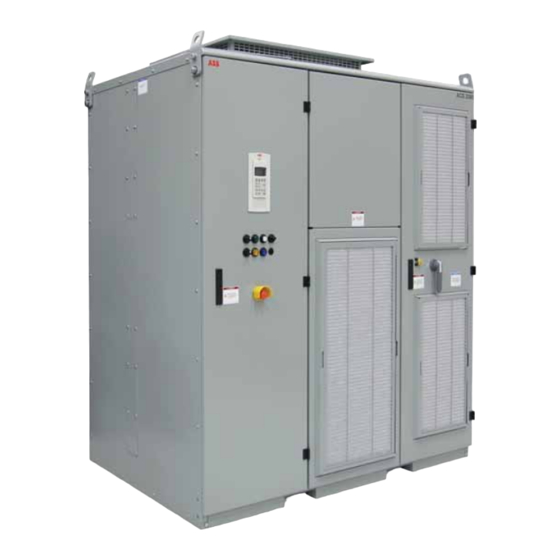
Chapter 2 - Power electronics and cabinet features Overview The ACS2000 is an air-cooled, general purpose variable frequency drive for the control of standard induction motors with 4 kV voltage. Due to the multi-level topology of the power electronic components, the... -
Page 42: Drive Topology
This section describes the main design features and introduces the major power electronic components of a typical ACS2000 drive. If you have ACS2000 with the integral input contactor disconnect option, refer to Appendix P, section 2.4 Electrical installation, for topology information. - Page 43 TEU - Terminal Entry Unit for line and MV switchgear guide, located on the motor cables (behind swing frame and CD, for additional information. access panels) Figure 2-2 - Frame 2 Overview ACS2000 User manual 2UEA001270 Rev. F 2-3 (28)
- Page 44 (MV Switchgear) and Appendix G - MV TEU - Terminal Entry Unit for line and switchgear guide, located on the CD, motor cables (behind swing frame and for additional information. access panels) Figure 2-2 - Frame 3 Overview 2-4 (28) 2UEA001270 Rev. F ACS2000 User manual...
-
Page 45: Ifu - Input Filter Unit
The AFE maintains the DC link voltage at the required level and provides unity power factor at the input terminals of the drive. Energy flow in driving mode Utility Customer Energy flow in braking mode (Regenerative operation only) DC link dV/dt filter ACS2000 User manual 2UEA001270 Rev. F 2-5 (28) - Page 46 The device combines high speed switching capabilities with high blocking voltage and low conduction losses. The phase modules can be removed from the cabinet for maintenance and service. 2-6 (28) 2UEA001270 Rev. F ACS2000 User manual...
-
Page 47: Figure 4-4 - Frame
Chapter 2 - Power electronics and cabinet features Frame 1 Frame 2 Frame 3 Legend Phase capacitor Gate drivers IGBT module Phase INT board Medium voltage IGBT assembly on connectors heat sink Figure 2-5 Phase module ACS2000 User manual 2UEA001270 Rev. F 2-7 (28) -
Page 48: Dc Link
When the DC link voltage has decreased below 25% of its nominal value, the capacitor in the phase modules begin to discharge. 2-8 (28) 2UEA001270 Rev. F ACS2000 User manual... - Page 49 When the switch is in the grounded position, the input filter, AFE, DC link, INU and dV/dt output filter of the drive are connected to the PE (protective earth) ground, provided none of the phase modules is extracted from the cabinet. Refer to Figure 2-8. ACS2000 User manual 2UEA001270 Rev. F 2-9 (28)
- Page 50 2-10 (28) 2UEA001270 Rev. F ACS2000 User manual...
- Page 51 Grounded O-(OFF) Ungrounded I -(ON) position position Legend GROUND SW RELEASED pilot light Grounding switch handle - grounded (OFF) position Grounding switch handle - ungrounded (ON) position Figure 2-9 Grounding the drive ACS2000 User manual 2UEA001270 Rev. F 2-11 (28)
-
Page 52: Inu - Inverter Unit
Figure 2-10 INU - INverter Unit multi-level topology and waveform The INU is composed of three identical phase modules (see section 2.2.3.1 Phase module). The phase modules can be removed from the cabinet for maintenance and service. 2-12 (28) 2UEA001270 Rev. F ACS2000 User manual... -
Page 53: Dv/Dt Filter
AC output. The filter protects the motor against excessive voltage rate of rise. The filter components are: inductors (1), resistors (2), and capacitors (3). DC link dV/dt filter Legend Inductor Resistors Capacitors To NP Figure 2-12 dV/dt filter schematic ACS2000 User manual 2UEA001270 Rev. F 2-13 (28) - Page 54 Chapter 2 - Power electronics and cabinet features Legend Inductor Resistors Capacitors Figure 2-13 - Frame 1 dV/dt filter (rear view shown) Legend Inductor Resistors Capacitors Figure 2-13 - Frame 2 dV/dt filter (front view shown) 2-14 (28) 2UEA001270 Rev. F ACS2000 User manual...
- Page 55 Chapter 2 - Power electronics and cabinet features Legend Inductor Resistors Capacitors Figure 2-13 - Frame 3 dV/dt filter (rear view shown) ACS2000 User manual 2UEA001270 Rev. F 2-15 (28)
-
Page 56: Doors And Door Locks
The ventilation grill can be removed The ventilation grills can be during operation to replace the filter removed during operation to mat. replace the filter mat. Figure 2-14 Door locks 2-16 (28) 2UEA001270 Rev. F ACS2000 User manual... -
Page 57: Door Safety Interlocking
Auxiliary power supply will remain live. Legend Kirk key Grounding switch (shown in grounded position) Grounding switch (shown in ungrounded position) Figure 2-15 Location of door safety interlocking ACS2000 User manual 2UEA001270 Rev. F 2-17 (28) -
Page 58: Power Supply Configurations
The Kirk key for this option is located behind the door of the disconnect section. Note: Auxiliary power may be provided by the integral input contactor disconnect on drives with this option. • Main power supply (eg. 4160 V) for the power electronic components 2-18 (28) 2UEA001270 Rev. F ACS2000 User manual... -
Page 59: Auxiliary Power Supply
2.4.1 Auxiliary power supply The ACS2000 drive system requires an auxiliary power supply to provide power for the internal controls, pre-charge system, and fan(s). This power is supplied via a 3-phase 480 V power feed (400 V and 600 V auxiliary supply voltages are available by option). -
Page 60: Figure 4-4 - Frame
480 V auxiliary power outage, communication to a higher- level control system will not be lost. This control supply is wired to terminal block X02. See Figure 2-17. 2-20 (28) 2UEA001270 Rev. F ACS2000 User manual... -
Page 61: Table 2-2 Single-Phase Power Supply Requirement
An additional 120 V power supply cable is required. Motor space heater currents of up to 5 A continuous are supported. ACS2000 User manual 2UEA001270 Rev. F 2-21 (28) -
Page 62: Main Power Supply Configuration
2.4.2 Main power supply configuration The ACS2000 4 kV drive includes an input filter unit which enables the drive to be connected directly to the 4160 V main power supply as shown in Figure 2-18. For drives with the integral input contactor disconnect, the power fuses are relocated to the switchgear, see Appendix P for details. -
Page 63: Teu - Terminal Entry Unit
The cables enter through the top or through the floor of the cabinet: the ACS2000 drive supports either method. The ground bus slotted hole feature supports both NEMA and IEC lugs. Legend... -
Page 64: Cooling
Air enters the front of the cabinet through ventilation grills, passes through the compartments and exits via the fan out the top of the drive. 2-24 (28) 2UEA001270 Rev. F ACS2000 User manual... - Page 65 If the filter mats are clogged and the pressure drop reaches the specified final pressure loss, the message Conv1CoolAirFilter is displayed on the CDP control panel and the alarm/fault pilot light on the control compartment door illuminates. ACS2000 User manual 2UEA001270 Rev. F 2-25 (28)
- Page 66 Figure 2-21 - Frame 1 Airflow - filter compartment (cross-section rear view) Legend Inlet grill IFU inductors Filter resistors Air outlets (Fans) Figure 2-21 - Frames 2, 3 Airflow - filter compartment (cross-section rear view) 2-26 (28) 2UEA001270 Rev. F ACS2000 User manual...
-
Page 67: Cabinet Design
IFU inductors (2), circulates up through access holes to the filter resistors(3), and exits to the fan (4). Cabinet design Heavy-duty 2.5 mm [12 gauge] external panels with integral frame structure incorporate cabinet strength and stability. ACS2000 User manual 2UEA001270 Rev. F 2-27 (28) - Page 68 Chapter 2 - Power electronics and cabinet features 2-28 (28) 2UEA001270 Rev. F ACS2000 User manual...
-
Page 69: Chapter 3 - Control System
The control compartment door can be opened to access the circuit boards. The swing frame can be opened for further access to the drive components: customer I/O connections and terminal blocks, etc. ACS2000 User manual 2UEA001270 Rev. F 3-1 (26) - Page 70 (option) X20 cabinet space heater input (option) terminal blocks 13 Pulse encoder (option) 14 Motor temperature supervision (option) 11, 13, 14 Swing frame interior Control compartment interior Figure 3-2 Control compartment interior 3-2 (26) 2UEA001270 Rev. F ACS2000 User manual...
-
Page 71: Control System Configuration And Main Components
ACS2000 User manual 2UEA001270 Rev. F 3-3 (26) -
Page 72: Amc (Application And Motor Controller) Circuit Board
Phase INT circuit boards inside the phase modules (see Figure 3-3). The main internal control devices and the peripheral input and output interfaces to the customer communicate with the AMC circuit board via fiber-optic cables. 3-4 (26) 2UEA001270 Rev. F ACS2000 User manual... - Page 73 DC link. NOTICE The ACS2000 must have exclusive control of closing the MV switchgear. Uncontrolled closing of the switchgear may cause damage to the drive. See Appendix G - MV switchgear guide for control details. ACS2000 supplied with the optional integral input contactor disconnect has this switching integral to the drive.
- Page 74 The switchgear disconnects the power supply when required by the process or when a fault occurs. Examples of switchgear compatible with the ACS2000 are MV circuit breakers, fused vacuum contactors or motor control centers. On drives equipped with the integral input contactor disconnect option, the MV switchgear is integrated within the drive.
-
Page 75: Local Control Panel
PC-based service tools: DriveWare software tools - includes software tools such as the commissioning and maintenance tools DriveWindow and DriveDebug, and DriveOPC for data transfer between ABB drives and ® Windows -based applications. DriveMonitor (Option) - a monitoring and diagnostics tool that allows access to the drive from any location in the world via a secure internet connection. - Page 76 • display and set parameters, • display information on the last 64 fault events. See Chapter 8 - Local operation and Chapter 9 - CDP control panel for further information. 3-8 (26) 2UEA001270 Rev. F ACS2000 User manual...
- Page 77 Figure 3-8 CDP control panel removal 3.2.2.3 Dimensions and weight Dimensions (H x W x D) 170 x 80 x 21 mm [6.7 x 3.2 x 0.8 in] Weight 0.2 kg [0.4 lbs] ACS2000 User manual 2UEA001270 Rev. F 3-9 (26)
- Page 78 MOTOR SP 1242 rpm POWER 86.0 kW Legend CDP control panel AMC circuit board of the INU (INverter Unit) AMC circuit board of the AFE (Active Front End) Figure 3-9 AMC circuit boards 3-10 (26) 2UEA001270 Rev. F ACS2000 User manual...
-
Page 79: Interface System
The drive can include optional expansion I/O that includes a customer communication module (IOEC4) and an internal module (IOEC3). These expansion modules provide extra inputs and outputs for control and supervision as may be required by ABB or the customer to support various control options. ACS2000 User manual 2UEA001270 Rev. -
Page 80: Table 3-1 Ioec Module Configuration
154, and the last digit, 1, means that our part is the first assembly on the page. This identification label number is the key to track electrical devices throughout the drive and in ABB documentation. 3-12 (26) 2UEA001270 Rev. -
Page 81: Table 3-2 Module Identification
If there is an optional expansion customer communication IOEC module, it will be DIN rail mounted just below the standard one. See Figure 3-12. ACS2000 User manual 2UEA001270 Rev. F 3-13 (26) - Page 82 Chapter 3 - Control system Legend Standard customer communication module IOEC2 (A1541) Optional customer communication module IOEC4 (A1621) Standard internal communication module IOEC1 (A1501) Optional internal communication module IOEC3 (A1581) Figure 3-12 IOEC module location 3-14 (26) 2UEA001270 Rev. F ACS2000 User manual...
-
Page 83: Standard Ioec2 (A1541) Customer Communication Module
AI2 10V -AI2 +AI2 AI3 20mA -AI3 +AI3 AI3 10V AI4 20mA -AI4 +AI4 AI4 10V -AO1 +AO1 +AO2 -AO2 IOEC I/O-INTERFACE Two analog outputs see Table 3-7 Figure 3-13 IOEC2 (A1541) module ACS2000 User manual 2UEA001270 Rev. F 3-15 (26) -
Page 84: Table 3-4 Standard Digital Output Signal Allocation
* Factory installed wiring for X10 terminal block. See Appendix G - MV switchgear guide, located on the CD, for additional MV switchgear control information. When the integral input contactor disconnect is installed, X10 is internal to the drive. Refer to Appendix P. 3-16 (26) 2UEA001270 Rev. F ACS2000 User manual... -
Page 85: Table 3-5 Standard Digital Input Signal Allocation
+0 V X13-10 Common * Not configurable When the integral input contactor disconnect is installed, these signals are prewired. External 120 V supply Wiring example - start/stop switch with external 120 V supply ACS2000 User manual 2UEA001270 Rev. F 3-17 (26) -
Page 86: Table 3-6 Standard Analog Input Signal Allocation
Analog output resolution 12 bit Terminal Channel Default setting Par. Group Signal level X31-6 AO1+ Motor speed act 0...20mA AO1- X32-6 Load impedance X31-7 AO2+ Motor torque act filt 250 Ω AO2- X32-7 3-18 (26) 2UEA001270 Rev. F ACS2000 User manual... -
Page 87: Optional Ioec4 (A1621) Customer Communication Module
AI2 10V -AI2 +AI2 AI3 20mA -AI3 +AI3 AI3 10V -AI4 +AI4 AI4 20mA AI4 10V -AO1 +AO1 -AO2 +AO2 IOEC I/O-INTERFACE Two analog outputs see Table 3-11 Figure 3-14 IOEC4 (A1621) module ACS2000 User manual 2UEA001270 Rev. F 3-19 (26) -
Page 88: Table 3-8 Optional Digital Output Signal Allocation
OFF command) X23-3 X24-1 Freely programmable (for motor cooling fan then X24-2 DO04 motor cooling fan ON command) X24-3 X25-1 Freely programmable X25-2 DO05 X25-3 X26-1 Freely programmable X26-2 DO06 X26-3 3-20 (26) 2UEA001270 Rev. F ACS2000 User manual... -
Page 89: Table 3-9 Optional Digital Input Signal Allocation
Motor vibration 1/bearing 1 (alarm trip) X13-4 Common X13-5 DI13 Ext mot trip (ovrtmp/ovrspd/space htr/fan) X13-6 Common X13-7 DI14 External motor alarm X13-8 Common X13-9 +24 V 24 V control logic +0 V X13-10 Common ACS2000 User manual 2UEA001270 Rev. F 3-21 (26) -
Page 90: Table 3-10 Optional Analog Input Signal Allocation
Table 3-11 Optional analog output signal allocation Analog output resolution 12 bit Terminal Channel Default setting Par. Group Signal level X31-6 AO1+ Freely programmable 0...20mA AO1- X32-6 Load impedance X31-7 AO2+ Freely programmable 250 Ω AO2- X32-7 3-22 (26) 2UEA001270 Rev. F ACS2000 User manual... -
Page 91: Fieldbus Communication Interfaces - Optional
See Appendix E - Wiring diagrams, located on the CD, to identify the adapter type installed in your drive. See Appendix B - Fieldbus adapter manuals, located on the CD, for detailed information. ACS2000 User manual 2UEA001270 Rev. F 3-23 (26) - Page 92 Higher-level control Figure 3-15 Fieldbus communication 3.3.4.4 Location The fieldbus adapter is mounted on a DIN rail inside the swing frame (see Figure 3-16). Legend Fieldbus adapter Figure 3-16 Fieldbus location 3-24 (26) 2UEA001270 Rev. F ACS2000 User manual...
-
Page 93: Pulse Encoder (Option)
These modules are suitable for connection of PT100 resistance thermometers in accordance with IEC60751 in 2, 3 or 4 conductor systems. See Appendix L - Motor temperature supervision, located on the CD, for detailed information. ACS2000 User manual 2UEA001270 Rev. F 3-25 (26) - Page 94 Chapter 3 - Control system 3-26 (26) 2UEA001270 Rev. F ACS2000 User manual...
-
Page 95: Chapter 4 - Transportation, Storage And Disposal
Compare the complete delivery with the purchase order and the packing list. If parts are missing or damaged, immediately inform the shipping company and the ABB service organization. We recommend that you photograph the damages and send the photographs to ABB. -
Page 96: Lifting And Transportation
Chapter 4 - Transportation, storage and disposal 4.1.2 Lifting and transportation Preparation is required to transport the ACS2000 drive properly. Take into consideration the height*, width, depth and weight of the drive. Height* Width Depth Figure 4-1 Transport dimensions (Frame 2 pictured) * The shipping pallet will add additional overall height. - Page 97 The drive should always be moved by level 2 certified rigger personnel. Less than 5° Legend Lifting brackets - each corner Slings Spreader bar (not provided) Lifting hooks Figure 4-2 Transporting the cabinet by crane using lifting brackets (Frame 3 pictured) ACS2000 User manual 2UEA001270 Rev. F 4-3 (8)
- Page 98 Front of drive Side of drive Legend Forklift pocket Lifting brackets Figure 4-3 Transporting the cabinet by forklift (Frame 2 pictured) 4-4 (8) 2UEA001270 Rev. F ACS2000 User manual...
-
Page 99: Storage
CD, for detailed information. The drive can be stored for up to one year in the original packaging as long as it is not damaged or opened. For information on longer storage periods contact the ABB service organization. 4.2.2 Storage... - Page 100 Chapter 4 - Transportation, storage and disposal Legend Desiccant bag Humidity sensor tab Figure 4-4 - Frame 1 Prepare drive for storage Legend Desiccant Humidity sensor tab Figure 4-4 - Frame 2 Prepare drive for storage 4-6 (8) 2UEA001270 Rev. F ACS2000 User manual...
- Page 101 Use polyethylene or equivalent for packaging furnished: • 0.3g/m /24h water vapor diffusion The storage conditions and the packaging should be checked regularly. Any damages that occur during the storage period should be repaired immediately. ACS2000 User manual 2UEA001270 Rev. F 4-7 (8)
-
Page 102: Storage And Handling Instructions For Spare Parts
Apply static-sensitive precautions when handling these components. Inspect the spare parts immediately after receipt for damages. Report any damage to the shipping company and the ABB service organization. Observe the following to maintain spare parts in good condition and to keep the warranty valid during the warranty period: •... -
Page 103: Chapter 5 - Mechanical Installation
Contact the ABB service organization if the condition of the installation site is not within the specifications or if the transportation or the installation require special measures. -
Page 104: Foundation Requirements
The cabinet roof is not designed as a mounting base for foreign devices, cable ducts, etc. Therefore, do not install any foreign device on the top of the drive. 5-2 (14) 2UEA001270 Rev. F ACS2000 User manual... -
Page 105: Dimensions And Clearances
Mounting hole sizes 5.4.3 Base mounting ABB recommends that the drive be attached to the floor during installation. There is one acceptable means to attach the cabinet to the floor: direct-to-floor mounting. Floor mounting hardware is not supplied by ABB. -
Page 106: Fan Outlet Box Installation - Frame 1 (If Required)
The box can be lifted by means of a forklift or a crane. Being careful not to damage the sealing gasket, line up the outlet box holes with the predrilled holes in the top of the drive for proper orientation. 5-4 (14) 2UEA001270 Rev. F ACS2000 User manual... -
Page 107: Fan Outlet Box And External Fan Installation - Frames 2, 3 (If Required)
WARNING Wiring connections will need to be made. Make sure no power is connected to the drive before proceeding with the fan installation. ACS2000 User manual 2UEA001270 Rev. F 5-5 (14) -
Page 108: Figure 5-4 - Frames
Make the wiring connections. Legend Terminal block X22 Wire numbers External fan power supply Figure 5-4a - Frame 2 External fan power supply connections Check that the flapper is moving freely. 5-6 (14) 2UEA001270 Rev. F ACS2000 User manual... -
Page 109: Redundant Fan Installation - Frame 1 (Option)
Consider the size and weight of the components when planning to lift them onto the top of drive. The fan components can be lifted by means of a forklift or a crane. Remove the cover and the fan from the redundant fan assembly. ACS2000 User manual 2UEA001270 Rev. F 5-7 (14) - Page 110 Remove the upper IFU (Input Filter Unit) panel to access the drive wiring for the redundant fan. Carefully feed the wires from the drive up into the fan unit housing and route to the terminal block. Make the wiring connections. 5-8 (14) 2UEA001270 Rev. F ACS2000 User manual...
-
Page 111: Figure 5-8 - Frame
Route the fan wires (see Figure 5-10 - Frame 1) and connect to the terminal block. Check that the flapper is moving freely. 10 Reattach the front panel and the cover of the fan unit. ACS2000 User manual 2UEA001270 Rev. F 5-9 (14) -
Page 112: Redundant Fan Installation And Removal Procedures - Frames 2, 3 (Option)
WARNING Wiring connections will need to be made. Make sure no power is connected to the drive before proceeding with redundant fan installation. 5-10 (14) 2UEA001270 Rev. F ACS2000 User manual... -
Page 113: Figure 5-6 - Frames
Remove the fan hole cover plate from the top of the drive. Lift and properly orientate the empty redundant fan box on top of the drive, being careful not to damage the sealing gasket. ACS2000 User manual 2UEA001270 Rev. F 5-11 (14) -
Page 114: Figure 5-7 - Frames
Carefully feed the wires from the drive up into the fan unit housing and route to the terminal block. Make the wiring connections. Legend Terminal block X23 Wire numbers Redundant fan power supply Figure 5-8 - Frame 2 Redundant fan power supply connections 5-12 (14) 2UEA001270 Rev. F ACS2000 User manual... - Page 115 Route the fan wires and connect to the terminal block. Check that the flapper is moving freely. Reattach the rear panel and the cover of the fan unit. Removal procedure is the reverse of the installation procedure. ACS2000 User manual 2UEA001270 Rev. F 5-13 (14)
- Page 116 Chapter 5 - Mechanical installation 5-14 (14) 2UEA001270 Rev. F ACS2000 User manual...
-
Page 117: Chapter 6 - Electrical Installation
When the electrical installation is completed, the main and auxiliary power supply to the drive must not be switched on without the consent of the ABB commissioning personnel. Take appropriate measures to prevent main and auxiliary power supply from being switched on during installation or maintenance. -
Page 118: Overview Of Installation Work
All cables and wiring must, at a minimum, follow the current NEC (National Electrical Code) Handbook requirements or equivalent, and must comply with all local codes. Any ABB recommendations will not replace these requirements. Codes address cable selection from a safety and fire protection point of view;... -
Page 119: Cables And Wires
Installation Installation should be in compliance with national codes, local codes, and standard industry practice for medium voltage equipment. ACS2000 User manual 2UEA001270 Rev. F 6-3 (16) -
Page 120: Ground Cable
Control and power cables should be crossed at an angle of 90°. Control cables are wired to the IOEC2, fieldbus adapter and terminal block X10. See Chapter 3 - Control system, for wiring details. 6-4 (16) 2UEA001270 Rev. F ACS2000 User manual... -
Page 121: Cable Entry
The unused cable entry is closed by a cover (6). Legend PE ground Power IN terminals Motor OUT terminals Strain relief Cable entry cover Figure 6-2 Terminal entry unit ACS2000 User manual 2UEA001270 Rev. F 6-5 (16) -
Page 122: Cable Entry For Ground Cable, Line Supply And Motor Cables
This aluminum plate is either attached to the top or the bottom access hole - whichever is receiving the cables. The unused entry access hole is covered by a steel plate. 6-6 (16) 2UEA001270 Rev. F ACS2000 User manual... -
Page 123: Ground Cable And Cable Shield Connections
Terminal details • Busbar dimensions: 75 mm [3 in] wide x 3.18 mm [0.125 in] thick • Hole diameters: 7 mm [0.28 in] for wire connections 13 mm [0.5 in] for fastening bolt ACS2000 User manual 2UEA001270 Rev. F 6-7 (16) -
Page 124: Recommended Grounding And Bonding Of The Drive System
Ground cable Bonding conductor Braid Cable shield Cable shield Earth electrode ACS2000 Motor/Load Mechanical MOTOR load Figure 6-5 Grounding and bonding drive equipment See Standard induction motor specifications for detailed cable information. 6-8 (16) 2UEA001270 Rev. F ACS2000 User manual... -
Page 125: Line Supply And Motor Cables
Enter the cables into the terminal entry unit to measure the conductor length. Mark the required conductor length, withdraw the cable and cut it to the correct length. ACS2000 User manual 2UEA001270 Rev. F 6-9 (16) - Page 126 Check the insulation of each cable with a megger before connecting it and verify that the results are within the specification of the cable manufacturer. Leave the cable conductors unconnected at both ends until the commissioning engineer has given his permission. 6-10 (16) 2UEA001270 Rev. F ACS2000 User manual...
-
Page 127: Cable Connection
Connect the shielded ends of all conductors and the shield of all cables to the PE (Protective Earth) ground bus (1 or 6 in Figure 6-8) • Connect the ground cable to the PE ground bus (1 or 6 in Figure 6-8) ACS2000 User manual 2UEA001270 Rev. F 6-11 (16) -
Page 128: Table 6-2 Hardware Requirements
This connection (see Figure 6-9) is recommended when connecting a cable lug (3) to a busbar (4): Legend Belleville washer Flat washer Cable lug Busbar Figure 6-9 Connection with Belleville spring and flat washer 6-12 (16) 2UEA001270 Rev. F ACS2000 User manual... - Page 129 Make sure the fuses are not blown. The red indicator pin should be flush with the top of the fuse. See Figure 6-11. If one fuse has blown, the other fuses may be degraded. ABB recommends that all fuses be replaced.
-
Page 130: Auxiliary Power, Control And Fieldbus Communication Cables
Project specific cable entry • Dimensions between point of cable entry and terminals See Appendix E - Wiring diagrams, located on the CD, for information on: • Designation, cross-reference and device-identification conventions 6-14 (16) 2UEA001270 Rev. F ACS2000 User manual... -
Page 131: Cable Preparation
Determine the required length of a cable between the point of entry and the connection point inside the cabinet and cut the cable to the required length before connection to avoid excess cable in the raceway. ACS2000 User manual 2UEA001270 Rev. F 6-15 (16) -
Page 132: Cable Connection
The terminals are suitable for wires with a maximum cross-section of 0.2 to 2.5 mm [24 to 12 AWG]. Maximum torque is 2.0 Nm [17.7 in-lbs]. The PE terminals can accommodate shielded cables up to 17 mm [0.67 in] in diameter. 6-16 (16) 2UEA001270 Rev. F ACS2000 User manual... -
Page 133: Chapter 7 - Commissioning
Chapter 7 - Commissioning Required qualification Commissioning, parameter adjustments and functional tests are only to be performed by qualified commissioning personnel certified by ABB. Procedure Information on the commissioning procedure and the start conditions for commissioning can be obtained from ABB. - Page 134 Chapter 7 - Commissioning 7-2 (6) 2UEA001270 Rev. F ACS2000 User manual...
-
Page 135: Commissioning Checklist
Electrical installation Types and cross sections of control cables suitable for the signal type and signal level Types and cross sections of power cables selected according to the ABB power cable specification Pulse encoder cable shields connected to “shield grounding point” and not connected... -
Page 136: Mv Switchgear
Chapter 7 - Commissioning MV switchgear Type of MV switchgear selected and wired per ABB MV switchgear specification MV switchgear ready to be tested with drive MV switchgear protection relay settings tested ® Safety devices (door locks, Kirk key, grounding switch, etc.) tested and in operation... -
Page 137: Power Supply
Low voltage auxiliary power available for start-up of drive according to the instructions in the User manual Miscellaneous Sufficient number and correct type of spare parts available Air conditioning of drive room ready for load run of drive Optional equipment ready ACS2000 User manual 2UEA001270 Rev. F 7-5 (6) - Page 138 Chapter 7 - Commissioning 7-6 (6) 2UEA001270 Rev. F ACS2000 User manual...
-
Page 139: Chapter 8 - Local Operation
Status messages • Alarm and fault messages • Viewing, setting parameters • Resetting alarm and fault messages • Activating the emergency-off circuit • Testing the bulbs of pilot lights and illuminated pushbuttons ACS2000 User manual 2UEA001270 Rev. F 8-1 (18) - Page 140 MV switchgear opens immediately and DC link discharges Motor coasts to a stop * See Chapter 9 - CDP control panel for further information on the CDP control panel. Figure 8-1 Local operator panel functions 8-2 (18) 2UEA001270 Rev. F ACS2000 User manual...
-
Page 141: Lamp-Test Function
When the drive is in ReadyRef state, it is running and operating according Ready ref to the set speed or torque reference value. When in remote control mode, ACS2000 User manual 2UEA001270 Rev. F 8-3 (18) - Page 142 The status message always alternates with the specific fault message. The type of shutdown depends on the fault class that the fault condition is assigned to in the drive software. 8-4 (18) 2UEA001270 Rev. F ACS2000 User manual...
-
Page 143: Start Sequence Of The Drive
Drive not grounded No emergency OFF No fault Ready on On command Charging MV switchgear closes AFE Ready ref Ready run Start command INU starts to modulate Ready ref Operation ACS2000 User manual 2UEA001270 Rev. F 8-5 (18) -
Page 144: Stop Sequence
Stop command to AFE MV switchgear opens DC link discharges Fan switches off after a delay AFE Ready on Ready on Actions: Drive is grounded Auxiliary supply is switched off (480 VAC) Not ready on 8-6 (18) 2UEA001270 Rev. F ACS2000 User manual... -
Page 145: Emergency-Off Sequence
Stop command to AFE MV switchgear opens INU stops to modulate Speed coasts down Not ready on Note: For the sake of simplicity, the flow diagrams of the AFE were omitted in the preceding diagrams. ACS2000 User manual 2UEA001270 Rev. F 8-7 (18) -
Page 146: Starting The Drive System
Chapter 8 - Local operation Starting the drive system ABB recommends you have the following documents at hand when starting the drive system for the first time after commissioning: • Appendix E - Wiring diagrams, located on the CD, to identify the circuit breakers to be switched on •... -
Page 147: Starting The Drive System Locally
When no alarms and faults are present and the drive is ready, the CDP control panel displays ReadyOn. 1 L -> 0.0 rpm ReadyOn StateINU MOTOR SP 0.00 rpm POWER 0.0 kW ACS2000 User manual 2UEA001270 Rev. F 8-9 (18) - Page 148 MOTOR SP 0.00 rpm POWER 0.0 kW Enter the setpoint. See section 9.4.3 Entering a setpoint for procedure. 1 L -> [600.0 rpm] 0 StateINU ReadyRun MOTOR SP 0.00 rpm POWER 0.0 kW 8-10 (18) 2UEA001270 Rev. F ACS2000 User manual...
-
Page 149: Stopping
MOTOR SP 300.00 rpm POWER 20.0 kW As long as the stop sequence is in progress, the drive can always be restarted by pressing the start key on the CDP control panel. ACS2000 User manual 2UEA001270 Rev. F 8-11 (18) -
Page 150: Energizing The Drive
Note: For drives with the integral input contactor disconnect option installed, refer to Appendix P for detailed information as some compartments such as TEU are still live after disconnect is opened. 8-12 (18) 2UEA001270 Rev. F ACS2000 User manual... -
Page 151: Procedure For Disconnecting The Drive From The Main Power Supply
DC link is discharged completely. When the DC link is discharged, the display shows ReadyOn. 1 L -> 600.0 rpm ReadyOn StateINU MOTOR SP 0.00 rpm POWER 0.0 kW ACS2000 User manual 2UEA001270 Rev. F 8-13 (18) - Page 152 When the grounding switch is in the grounded position, the status line of the display alternates between DCGnd NOpen, NotReadyOn, AFE NotRdy. 1 L -> 600.0 rpm DCGnd NOpen DCGnd NOpen StateINU NotReadyOn MOTOR SP 0.00 rpm AFE NotRdy POWER 0.0 kW 8-14 (18) 2UEA001270 Rev. F ACS2000 User manual...
- Page 153 Line supply cables PE ground bus 4-way grounding set Figure 8-2 Connecting a grounding set Switch off all auxiliary The drive is safely grounded, and safe access is possible. voltages from external sources. ACS2000 User manual 2UEA001270 Rev. F 8-15 (18)
-
Page 154: Emergency-Off
The DC link of the drive discharges. • The status line of the CDP control panel alternates between the messages EmergeOff, NotReadyOn. 600.0 rpm 1 L -> EmergeOff EmergeOff StateINU NotReadyOn MOTOR SP 0.00 rpm POWER 0.0 kW 8-16 (18) 2UEA001270 Rev. F ACS2000 User manual... -
Page 155: Procedure For Starting The Drive System After An Emergency Shutdown
1 L -> 0.0 rpm ReadyOn StateINU MOTOR SP 0.00 rpm POWER 0.0 kW Now, the main power supply can be connected to the drive again and the drive system can be started up. ACS2000 User manual 2UEA001270 Rev. F 8-17 (18) - Page 156 Chapter 8 - Local operation 8-18 (18) 2UEA001270 Rev. F ACS2000 User manual...
-
Page 157: Chapter 9 - Cdp Control Panel
1242 rpm POWER 86.0 kW Enter key, executes a procedure Local/remote selection key Reset key Reference key Start key Forward key Keypad 10 Reverse key 11 Stop key Figure 9-1 CDP control panel ACS2000 User manual 2UEA001270 Rev. F 9-1 (24) -
Page 158: Overview Of Cdp Control Panel Functions
Function mode, selected by the FUNC key See section 9.3.4 Function mode for further information. • Drive selection mode, selected by the DRIVE key See section 9.3.5 Drive selection mode for further information. 9-2 (24) 2UEA001270 Rev. F ACS2000 User manual... -
Page 159: Identification Mode
1 L -> 0.0 rpm DCGndNopen The status line of the DCGndNopen StateINU NotReadyOn display alternates MOTOR SP 0.00 rpm between POWER 0.0 kW DCGndNopen, NotReadyOn. ACS2000 User manual 2UEA001270 Rev. F 9-3 (24) -
Page 160: Actual Signal Display Mode
Group 08 - Status words Group 09 - Fault and alarm words See Appendix M - Signal and parameter table, located on the CD, for the complete list of selectable actual signals. 9-4 (24) 2UEA001270 Rev. F ACS2000 User manual... - Page 161 Changing from the fault display mode to other display modes is possible without resetting the fault first. When no keys are pressed, the fault or warning text is displayed as long as the fault is pending. ACS2000 User manual 2UEA001270 Rev. F 9-5 (24)
- Page 162 When in actual signal display mode, the fast up/down keys allow the signal display and fault user to toggle between actual signal display and fault history display. history 1 L -> 600.0 rpm 1 LAST FAULT +Overspeed 070730 12:30:02.3256 9-6 (24) 2UEA001270 Rev. F ACS2000 User manual...
- Page 163 1 L -> 600.0 rpm the corresponding slow navigation ReadyRun StateINU key. A blinking cursor MOTOR SP 600.00 rpm indicates the POWER 75.0 kW selected row. ACS2000 User manual 2UEA001270 Rev. F 9-7 (24)
- Page 164 1000 V To accept the selection and to return to the actual signal 1 L -> 600.0 rpm display mode, press ReadyOn the ENTER key. StateINU MOTOR SP 0.00 rpm NP VOLT 9-8 (24) 2UEA001270 Rev. F ACS2000 User manual...
- Page 165 600.0 rpm 1 L -> navigation key. The up key selects the LAST FAULT previous, the down + AMC: Fault Class 1 key the next fault. 9 H 38 MIN 48 S ACS2000 User manual 2UEA001270 Rev. F 9-9 (24)
- Page 166 1 L -> 600.0 rpm ACS2000 FAULT MCB CloseControl To reset the fault, press the RESET key. 1 L -> 600.0 rpm ReadyOn StateINU MOTOR SP 0.00 rpm POWER 0.0 kW 9-10 (24) 2UEA001270 Rev. F ACS2000 User manual...
-
Page 167: Parameter Mode
21.19 - MV switchgear available signal Group 23 - Speed reference See Appendix M - Signal and parameter table, located on the CD, for further information on the parameters, their settings and functions. ACS2000 User manual 2UEA001270 Rev. F 9-11 (24) - Page 168 77 SYSTEM CONFIG Parameter number and name 01 INU IdentifySel Parameter value INU1 (MASTER) Selects the parameter mode Selects the parameter number and name Selects the parameter value Enters change mode Acknowledges the selection 9-12 (24) 2UEA001270 Rev. F ACS2000 User manual...
- Page 169 21 START/STOP MCB FUNC 07 PROCESS STOP MODE STOP RAMP To enter the parameter setting function, press the ENTER key. 1 L -> 600.0 rpm 21 START/STOP MCB FUNC 07 PROCESS STOP MODE [STOP RAMP] ACS2000 User manual 2UEA001270 Rev. F 9-13 (24)
- Page 170 1 L -> 600.0 rpm the mode keys. The selected CDP control 21 START/STOP MCB FUNC panel mode is entered. 07 PROCESS STOP MODE STOP RAMP 9-14 (24) 2UEA001270 Rev. F ACS2000 User manual...
-
Page 171: Function Mode
The function mode is used to set the display contrast. Status line 0.0 rpm 1 L -> UPLOAD <= <= Selectable functions DOWNLOAD => => CONTRAST Selects the function mode Selects the line Acknowledges the selection ACS2000 User manual 2UEA001270 Rev. F 9-15 (24) - Page 172 To enter the contrast setting function, press the ENTER key. 0.0 rpm 1 L -> CONTRAST To change the contrast value, press the corresponding slow 1 L -> 0.0 rpm navigation key. CONTRAST 9-16 (24) 2UEA001270 Rev. F ACS2000 User manual...
- Page 173 To cancel the setting and keep the original selection, press any of 0.0 rpm 1 L -> the mode keys. The selected CDP control UPLOAD <= <= panel mode is entered. DOWNLOAD => => CONTRAST ACS2000 User manual 2UEA001270 Rev. F 9-17 (24)
-
Page 174: Drive Selection Mode
ID number of AFE: 2 Status line ACS2000AFE Device type 4k SingleINU Application SW version LDAI5500 Drive identification ID-Number Selects the drive mode Selects the AMC circuit board (AFE or INU) Acknowledges the selection 9-18 (24) 2UEA001270 Rev. F ACS2000 User manual... - Page 175 AFE will stop modulating and the drive will shut down. If the drive is stopped and the CDP control panel is set to LOCAL, the drive cannot be started up. LOC/REM key ACS2000 User manual 2UEA001270 Rev. F 9-19 (24)
-
Page 176: Operational Commands
To select local control, Local control location press the LOC / REM key. The local control location is indicated by the letter L. 600.0 rpm ReadyRun StateINU 0.00 rpm MOTOR SP POWER 0.0 kW 9-20 (24) 2UEA001270 Rev. F ACS2000 User manual... - Page 177 CDP control panel is switched to remote. The letter L remains on the display until the LOC / REM key is pressed. ACS2000 User manual 2UEA001270 Rev. F 9-21 (24)
-
Page 178: Setting The Direction Of Rotation
The direction of the arrow on the display changes to the new direction when the motor has reached zero speed. 9-22 (24) 2UEA001270 Rev. F ACS2000 User manual... -
Page 179: Entering A Setpoint
MOTOR SP 600.00 rpm POWER 75.0 kW To exit the setpoint setting mode, press any of the mode keys. 1 L -> 550.0 rpm ReadyRun StateINU MOTOR SP 550.00 rpm POWER 75.0 kW ACS2000 User manual 2UEA001270 Rev. F 9-23 (24) -
Page 180: Run Status Indication
MOTOR SP POWER 0.0 kW 1 L -> 600.0 rpm ReadyRun StateINU MOTOR SP 600.00 rpm POWER 75.0 kW 600.0 rpm 1 L -> ReadyRef StateINU MOTOR SP 600.00 rpm POWER 75.0 kW 9-24 (24) 2UEA001270 Rev. F ACS2000 User manual... -
Page 181: Chapter 10 - Troubleshooting And Maintenance
To maintain safe and reliable operation of the drive, ABB recommends taking out a service contract with the ABB service organization. For more information contact the ABB service organization. See section General information on manual and equipment for contact information. -
Page 182: 10.1.7 Further Information
Figure 10-1. The letter A represents the kind of part we have, an assembly, the next three digits are the page number the part is located on, page 146, and the last digit, 1, means that our part is 10-2 (32) 2UEA001270 Rev. F ACS2000 User manual... -
Page 183: 10.2.2 Cables And Wires
Chapter 10 - Troubleshooting and maintenance the first assembly on the page. This identification label number is the key to track electrical devices throughout the drive and in ABB documentation. Technical details and part numbers of the components are provided in Appendix F - Spare Parts list, located on the CD. -
Page 184: 10.3.2 Error Message Levels
In the above example: • 4. +Fault DC Undervoltage is the reason for the failure of the drive, as it occurred first. • The message 3. +Fault AMC: Fault Class 1 classifies the fault. 10-4 (32) 2UEA001270 Rev. F ACS2000 User manual... -
Page 185: 10.3.3 Standard Troubleshooting Procedure
Try to rectify the fault, following the instructions in Appendix N - Troubleshooting guide, located on the CD. Contact ABB service if a fault cannot be rectified. When contacting ABB, have the following data available about the fault occurrence: •... -
Page 186: 10.3.4 Malfunctioning Grounding Switch
If there are any, look up the messages in Appendix N - Troubleshooting guide, located on the CD, and follow the instructions. Try to rectify the reason for the alarms and faults, and then press the reset key on the CDP control panel. 10-6 (32) 2UEA001270 Rev. F ACS2000 User manual... -
Page 187: 10.3.5 Leds And Switches On Pcbs And Ioec I/O Devices
Chapter 10 - Troubleshooting and maintenance Contact ABB service if the cause for the malfunctioning grounding switch cannot be rectified. See section General information on manual and equipment for contact information. 10.3.5 LEDs and switches on PCBs and IOEC I/O devices The following section provides an overview on the meaning of LEDs and switches of the main circuit boards and IOEC I/O devices. - Page 188 Each IOEC module has a unique cluster address that identifies the module in the software and links it to a parameter. See Appendix E - Wiring diagrams, located on the CD, for information on IOEC switch settings. 10-8 (32) 2UEA001270 Rev. F ACS2000 User manual...
-
Page 189: Table 10-2 Fieldbus Adapters
See Appendix E - Wiring diagrams, located on the CD, to identify the adapter type installed in your drive. See Appendix B - Fieldbus adapter manuals, located on the CD, for detailed information. ACS2000 User manual 2UEA001270 Rev. F 10-9 (32) -
Page 190: Maintenance
Before energizing the drive again, make sure that: • All foreign objects are removed from the drive. • All internal and external covers are securely fastened and all doors are closed, locked and / or bolted. 10-10 (32) 2UEA001270 Rev. F ACS2000 User manual... - Page 191 Close the doors and cover openings completely when work is discontinued. Any foreign matter which accidentally dropped into the cabinet must be retrieved. Metallic dust, in particular, could cause malfunction and damage when the drive is energized. ACS2000 User manual 2UEA001270 Rev. F 10-11 (32)
-
Page 192: 10.4.3 Service Access
Legend TEU (Terminal Entry Unit) Filter compartment Figure 10-6 - Frame 1 Front service access 10-12 (32) 2UEA001270 Rev. F ACS2000 User manual... - Page 193 Figure 10-6 - Frame 2 Front service access The ACS2000 is designed to allow all service access from the front of the drive. The bolted plates can be removed to access the terminal entry unit (1), and the filter compartment (2).
- Page 194 Chapter 10 - Troubleshooting and maintenance 10.4.3.1 Rear service access Legend AFE/INU compartment Filter compartment (Terminal Entry Unit) Figure 10-7 - Frame 1 Rear service access 10-14 (32) 2UEA001270 Rev. F ACS2000 User manual...
- Page 195 Chapter 10 - Troubleshooting and maintenance Legend AFE/INU compartment Filter compartment TEU (Terminal Entry Unit) Figure 10-7 - Frame 2 Rear service access ACS2000 User manual 2UEA001270 Rev. F 10-15 (32)
- Page 196 The covers enable rear access to the AFE/INU (Active Front End/INverter Unit) compartment (1), the filter compartment (2) and the TEU (Terminal Entry Unit) (3). 10-16 (32) 2UEA001270 Rev. F ACS2000 User manual...
-
Page 197: 10.4.4 Visual Checks On The Drive
Chapter 10 - Troubleshooting and maintenance 10.4.4 Visual checks on the drive Check the drive and its immediate vicinity visually at the intervals stated in Appendix A - ACS2000 maintenance schedule, located on the CD, and pay attention to the following items: •... -
Page 198: 10.4.6 Checking Wire And Cable Connections
Location The filter mats are located behind the ventilation grills of the INU (1), AFE (2), and Input filter (3) sections. Legend Input filter Figure 10-8 - Frame 1 Filter mat locations 10-18 (32) 2UEA001270 Rev. F ACS2000 User manual... - Page 199 Chapter 10 - Troubleshooting and maintenance Legend Input filter Figure 10-8 - Frame 2 Filter mat locations ACS2000 User manual 2UEA001270 Rev. F 10-19 (32)
- Page 200 Also, pay attention that dust accumulated on the filter mat is not sucked into the cabinet. Note: ABB recommends removing the old filter mat by rolling it down from the top to the bottom.
- Page 201 Step 5. Remove the filter mat Remove the filter mat, being careful not to disturb accumulated dust, by rolling the mat down from the top to the bottom. ACS2000 User manual 2UEA001270 Rev. F 10-21 (32)
-
Page 202: Figure 5-5 - Frame
• Filter class: G3 (EN779) • Thickness: approximately 10 mm [0.4 in] • ABB supplies replacement filter mats as specified in Table 10-3. Table 10-3 Filter mat identification INU and AFE Filter Width... - Page 203 Replace the ventilation grill Clean the grill, removing any dust or accumulated dirt. Position the grill over the door slot and slide into the channel. Lower the grill into place. Ventilation grill Slot Completely installed ACS2000 User manual 2UEA001270 Rev. F 10-23 (32)
-
Page 204: 10.4.8 Replacing A Phase Module
WARNING Original phase modules shipped with drive should not be interchanged with another unit without contacting ABB for guidance, as they are designed to meet the current requirements of the specific type code listed on the unit. -
Page 205: Figure 10-6 - Frame
Suggest two people module kit 2, 3 Rails (Qty. 2) Comes with phase Requires lifting hoist and module kit bracket 2, 3 Hoist lift kit 2UEA002561 Not required for Frame 1 phase module replacement ACS2000 User manual 2UEA001270 Rev. F 10-25 (32) - Page 206 Live-Dead-Live check on incoming terminals. See Chapter 1 - Safety, section 8.7 De-energizing Grounding the drive and Chapter 6 - Electrical switch installation, if you need further (shown in information. grounded position) 10-26 (32) 2UEA001270 Rev. F ACS2000 User manual...
- Page 207 After the circuit breakers have been switched off, the located on the CD, to identify the charging transformer and the fan unit are still circuit breakers that remove connected to their power supplies. auxiliary power from the drive. ACS2000 User manual 2UEA001270 Rev. F 10-27 (32)
- Page 208 • Slide the phase module tray tool in, until it makes contact with the metal flange on both sides of the NP frame. 10-28 (32) 2UEA001270 Rev. F ACS2000 User manual...
- Page 209 Hold the phase module by the handle and pull it out slowly until it is flush with the leading edge of the tray. Note: Verify that the module tray tool is firmly in place during this step. ACS2000 User manual 2UEA001270 Rev. F 10-29 (32)
- Page 210 Frame 2, the hoist is used. Refer to 10.4.8.2 Dimensions and weight for details on weights, replacement part numbers and special tools. 10-30 (32) 2UEA001270 Rev. F ACS2000 User manual...
- Page 211 12 Gently push the phase module back into the rack, ensuring cables are not pinched against the cabinet, as far as it goes. Tighten the fastening bolts that secure module to cabinet on each side. ACS2000 User manual 2UEA001270 Rev. F 10-31 (32)
- Page 212 NOTICE procedures, unground, and start the drive. If you need further assistance, please contact ABB See Chapter 8 - Local operation, Medium Voltage Drives Technical Support at 1-800- 8.5.3 Starting the drive system 435-7365 Option 4. Please have the serial number of locally if you need information on the ACS2000 unit ready for reference.
- Page 214 Contact us ABB Inc. Medium Voltage Drives 16250 W. Glendale Drive New Berlin, WI 53151 Phone: 800-752-0696 Fax: 262-785-3322 E-Mail: mv.drives.sales@us.abb.com www.abb.us/drives...