
Related Manuals for Ritron RF320 Series


Summary of Contents for Ritron RF320 Series
- Page 1 RF320-Series Ritron VHF/UHF Radios 10/12 C o p y r i g h t © 2 0 1 2 C a m p b e l l S c i e n t i f i c , I n c .
- Page 3 Warranty “PRODUCTS MANUFACTURED BY CAMPBELL SCIENTIFIC, INC. are warranted by Campbell Scientific, Inc. (“Campbell”) to be free from defects in materials and workmanship under normal use and service for twelve (12) months from date of shipment unless otherwise specified in the corresponding Campbell pricelist or product manual.
- Page 4 Assistance Products may not be returned without prior authorization. The following contact information is for US and international customers residing in countries served by Campbell Scientific, Inc. directly. Affiliate companies handle repairs for customers within their territories. Please visit www.campbellsci.com to determine which Campbell Scientific company serves your country.
-
Page 5: Table Of Contents
Table of Contents PDF viewers: These page numbers refer to the printed version of this document. Use the PDF reader bookmarks tab for links to specific sections. 1. Introduction ..............1 2. Cautionary Statements..........1 Licensing....................1 RF Energy Exposure ................1 2.2.1 Compliance with RF Exposure Standards........2 2.2.2 Guidelines ..................3 2.2.3 Instructions..................3 2.2.4 Antennas ..................3... - Page 6 6-2. Radio-to-modem interface cable wiring diagram ......10 Tables 2-1. Rated Power and Recommended Lateral Distance......3 3-1. RF320 Series Model Numbers to Ritron Model Number....4 7-1. RF320 Series Programmed Settings ..........14 8-1. LED Status Indications..............18 8-2.
-
Page 7: Introduction
RF320-Series Ritron VHF/UHF Radios Introduction This manual provides instructions for the installation and operation of RF320- series radios within a Campbell Scientific radio telemetry network. The RF320-series radios can be interfaced with Campbell Scientific’s RF500M or RF310M radio modems at an RF base, RF remote, or RF repeater location to achieve wireless data transmissions. -
Page 8: Compliance With Rf Exposure Standards
RF exposure and to satisfy compliance requirements. 2.2.1 Compliance with RF Exposure Standards Your Ritron two-way radio is designed and tested to comply with a number of national and international standards and guidelines (listed below) regarding human exposure to radio frequency electromagnetic energy. This radio... -
Page 9: Guidelines
RF320-Series Ritron VHF/UHF Radios • Institute of Electrical and Electronic Engineers (IEEE) C95. 1-1999 Edition. Copyright Telecommunications Industry Association. To control exposure to yourself and others and ensure compliance with the occupational/controlled environment exposure limits, always adhere to the following procedures. -
Page 10: Fcc Label
Check model information against the shipping documents to ensure the expected products and the correct length of cables were received. TABLE 3-1. RF320 Series Model Numbers to Ritron Model Number RF320 Series Ritron... -
Page 11: Overview
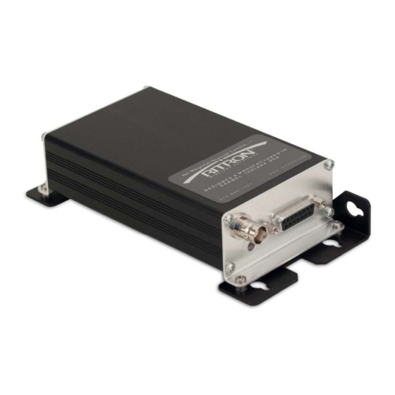
RF320-Series Ritron VHF/UHF Radios Overview FIGURE 4-1. RF320-Series Radio As offered by Campbell Scientific, RF320-series radios comprise a single board VHF/UHF FM RF transceiver module encased in an anodized, extruded aluminum enclosure with brushed aluminum end caps. Located on one end cap are two connectors and a LED view port. -
Page 12: Specifications
RF320-Series Ritron VHF/UHF Radios Specifications RF320 RF321/322/323 GENERAL DTX-145 DTX-445 Ritron Module: FCC ID: AIERIT17-145 AIERIT17-445 Industry Canada ID: 1084A-RIT17145 1084A-RIT17445 FCC Rule Parts: Industry Canada Rule Parts: RSS-119 Frequency Range: 136 to 174 MHz RF321: 400.5 to 416.5 MHz... - Page 13 RF320-Series Ritron VHF/UHF Radios RF320 RF321/322/323 Frequencies Unusable: Tx and Rx Steps: 411 to 429 MHz Band: 144 MHz (± 10 kHz) 158.4 MHz (± 10 kHz) 172.8 MHz (± 10 kHz) 417.60000 417.58750 418.03750 417.59375 Rx Steps: 187.1925 MHz 418.04375...
-
Page 14: Installation
RF320-Series Ritron VHF/UHF Radios RF320 RF321/322/323 RSSI squelch sensitivity: PC adjustable; factory set for -106 dBm PC adjustable; factory set for -121 dBm Noise squelch sensitivity: AUX OUT frequency response: 12 – 2500 Hz @ +1 / -3 dB AUX OUT level range: 0 to 3 V peak-to-peak >... -
Page 15: Interconnect
RF320-Series Ritron VHF/UHF Radios Interconnect FIGURE 6-1 illustrates the interconnection of an RF320-series radio in a typical installation. The depicted interconnect will be the same for an installation of the radio at either an RF base, RF remote, or RF repeater location. -
Page 16: System Power Supply
RF320-Series Ritron VHF/UHF Radios FIGURE 6-2. Radio-to-modem interface cable wiring diagram 6.2.1 System Power Supply The RF320 radio should be connected to a DC power source of not less than 9 Vdc and not more than 17 Vdc with a capacity of 2 A. For optimal performance, it is recommended that the supply voltage be maintained between 12.5 to 14.0 Vdc. -
Page 17: Antenna
RF320-Series Ritron VHF/UHF Radios 6.2.2 Antenna The antenna and all interconnecting cables, connectors, and adapters are critical elements of an RF link. It is essential that these components be selected to match the operational parameters of the intended system. The primary considerations when selecting an antenna are bandwidth and gain. -
Page 18: Installation Best Practices
RF320-Series Ritron VHF/UHF Radios radiated in the same direction by an isotropic antenna is defined as the antenna gain and is expressed in dBi. An isotropic antenna is a theoretical concept and doesn’t exist in nature. When actually measuring antenna gain in the laboratory, a half-wave dipole is used as the reference antenna. -
Page 19: Operation
RF320-Series Ritron VHF/UHF Radios Connectors All exposed RF connectors should be weatherproofed. A good method is to apply overlapping wraps of a good quality mastic tape, extending several inches beyond either side of the connection, then cover the mastic tape with tight, overlapping wraps of a good quality vinyl tape. -
Page 20: Link Design
TABLE 7-1. Alteration of these settings could adversely affect the operation of the radio telemetry network. It is recommended that Campbell Scientific be consulted before any changes are made. TABLE 7-1. RF320 Series Programmed Settings Parameter Setting Tx Time Out Time:... -
Page 21: Link Budget
RF320-Series Ritron VHF/UHF Radios 7.1.1 Link Budget Simply stated, the link budget is the difference, in dB, between the RF signal level arriving at the input to the remote radio ( known as the received signal strength) and the minimum signal level required by the receiver for proper communication (known as the receiver sensitivity). -
Page 22: Troubleshooting/Maintenance
RF320-Series Ritron VHF/UHF Radios the received signal strength. There exists an area about the centerline of an EM-wave propagation path that must be clear of obstructions. This area is termed the Fresnel zone (pronounced fray-nel) and the property that must be determined for a path of propagation is the Fresnel zone clearance. -
Page 23: Digital Multimeter (Dmm)
RF320-Series Ritron VHF/UHF Radios 8.1.1.1 Digital Multimeter (DMM) For verifying supply voltages, current drain, and the continuity of cables and interconnect wiring, an inexpensive (a high level of accuracy is not required) DMM is essential. Some representative equipment and manufacturers are listed below. -
Page 24: Hand-Held Rf Channel Scanner
RF320-Series Ritron VHF/UHF Radios 8.1.1.4 Hand-Held RF Channel Scanner A scanner can be used to detect the RF emissions of the radio and display the frequency, thus verifying the operating frequency. An example of an inexpensive scanner is listed below. -
Page 25: Radio Functional Checks
RF320-Series Ritron VHF/UHF Radios TABLE 8-2. Radio Troubleshooting Guide Indication Probable Cause Corrective Action Radio LED blinking red in receive Internal fault with transceiver Cycle power to the radio. If the mode module fault persists, replace the radio. Radio LED blinking red with Internal fault with transceiver Cycle power to the radio. -
Page 26: Input Voltage Checks
RF320-Series Ritron VHF/UHF Radios For a number of the following procedures, it will be necessary to manually key the radio’s transmitter. Campbell Scientific’s push-to-talk switch accessory (CSI# 13588) is used for this purpose. Connect the push-to-talk switch to the middle 10-pin connector of the radio-to-modem interface cable. -
Page 27: Operating Frequency Check (Rf Scanner)
RF320-Series Ritron VHF/UHF Radios connect the input of an RF wattmeter to the radio’s antenna connector. Connect the output of the RF wattmeter to an RF dummy load with a minimum power rating of 5 W and an operating frequency range matching that of the radio. - Page 28 RF320-Series Ritron VHF/UHF Radios...
-
Page 29: Glossary
Appendix A. Glossary Antenna: That part of a radio communications system intended to radiate and/or collect radio frequency energy. Antenna Gain: A relative measure of an antenna’s ability to direct or concentrate radio frequency energy in a particular direction or pattern. Typically measured in dBi or dBd. - Page 30 Appendix A. Glossary Dipole Antenna: The most common wire antenna. Length is equal to one-half of the wavelength for the frequency of operation. Fed by coaxial cable. Dummy Load: A device that serves as a transmitter’s antenna without radiating radio waves. Generally a resistive device that’s impedance is matched to the transmitter.
- Page 31 Appendix A. Glossary Insertion Loss: The loss in signal strength due to the insertion of a device in series with a signal path. Typically measured over the intended operating frequency range of the device and expressed in dB. Isotropic: A theoretical “isotrope” is a single point in free space that radiates energy equally in every direction similar to the sun.
- Page 32 Appendix A. Glossary Propagation: The travel of a signal through a medium such as air or free space. Radio Frequency (RF): Typically a frequency from 20 kHz to 100 GHZ. RF is usually referred to whenever a signal is radiated through an enclosed medium like a transmission cable or air.
- Page 33 Appendix A. Glossary caused by the interference of incident and reflective waves traversing the transmission line. Therefore, SWR can be calculated from the forward and reflected power measurements as follows: − Where: = Reflected Power = Forward Power Tone Squelch: A receiver function whereby the audio or data output is inhibited whenever one of a select number of sub-audible tones or digital codes is not detected in the received signal.
- Page 34 Appendix A. Glossary...
- Page 36 Campbell Scientific Companies Campbell Scientific, Inc. (CSI) 815 West 1800 North Logan, Utah 84321 UNITED STATES www.campbellsci.com • info@campbellsci.com Campbell Scientific Africa Pty. Ltd. (CSAf) PO Box 2450 Somerset West 7129 SOUTH AFRICA www.csafrica.co.za • cleroux@csafrica.co.za Campbell Scientific Australia Pty. Ltd. (CSA) PO Box 8108 Garbutt Post Shop QLD 4814 AUSTRALIA...