ABB ACS 800-17 Hardware Manual
Hide thumbs
Also See for ACS 800-17:
- Hardware manual (236 pages) ,
- Hardware manual (96 pages) ,
- Manual (42 pages)
Table of Contents
Advertisement
Quick Links
Advertisement
Table of Contents

Related Manuals for ABB ACS 800-17


Summary of Contents for ABB ACS 800-17
- Page 1 ACS 800 Hardware Manual ACS800-17 Drives (75 to 1120 kW)
- Page 3 ACS800-17 Drives (75 to 1120 kW) Hardware Manual 3AFE 64681338 Rev B EFFECTIVE: 10.3.2003 ã 2003 ABB Oy. All Rights Reserved.
-
Page 5: Safety Instructions
Safety instructions What this chapter contains This chapter contains safety instructions you must follow when installing, operating and servicing the drive. If ignored, physical injury or death may follow, or damage may occur to the drive, the motor or driven equipment. Read the safety instructions before you work on the unit. -
Page 6: Installation And Maintenance Work
Installation and maintenance work These warnings are intended for all who work on the drive, motor cable or motor. Ignoring the instructions can cause physical injury or death. WARNING! • Only qualified electricians are allowed to install and maintain the drive. •... - Page 7 WARNING! • Make sure that dust from drilling does not enter the drive when installing. Electrically conductive dust inside the unit may cause damage or lead to malfunction. • Fastening the cabinet by riveting or welding is not recommended. However, if the cabinet is fastened by welding, connecting the return wire improperly may damage electronic circuits in the cabinet.
-
Page 8: Grounding
Grounding These instructions are intended for all who are responsible for the grounding of the drive. Incorrect grounding can cause physical injury, death or equipment malfunction and increase electromagnetic interference. WARNING! • Ground the drive, the motor and adjoining equipment to ensure personnel safety in all circumstances, and to reduce electromagnetic emission and pick- •... -
Page 9: Operation
Operation These warnings are intended for all who plan the operation of the drive or operate the drive. Ignoring the instructions can cause physical injury or death or damage the equipment. WARNING! • If the drive is equipped with an optional brake unit, make sure there are inverters connected to the intermediate circuit before start. -
Page 10: Permanent Magnet Motor
Permanent magnet motor These are additional warnings concerning permanent magnet motor drives. WARNING! Do not work on the drive when the permanent magnet motor is rotating. Also when the supply power is switched off, a rotating permanent magnet motor feeds power to the intermediate circuit of the drive and also the supply connections become live (even when the inverter is stopped!). -
Page 11: Table Of Contents
Table of contents Safety instructions What this chapter contains ............5 Use of warnings and notes . - Page 12 Moving of the shipping split ............29 by crane .
- Page 13 Routing the cables ............. . 56 Control cable ducts .
- Page 14 Installation checklist What this chapter contains ............85 General .
- Page 15 Transportation ..............109 Disposal .
- Page 16 Table of contents...
-
Page 17: Introduction
Introduction Overview of the manual Study this manual carefully before installing, commissioning, operating or servicing the drive. We expect that you have a basic knowledge of physical and electrical fundamentals, electrical wiring practices, electrical components and electrical schematic symbols. ACS800-17 drives consist of a Supply Section and a Drive Section. This manual covers: •... -
Page 18: Inquiries
Inquiries Any inquiries about the product should be addressed to the local ABB representative, quoting the type code and the serial number of the unit. If the local ABB representative cannot be contacted, inquiries should be addressed to ABB Oy, Helsinki, Finland. -
Page 19: Hardware Description
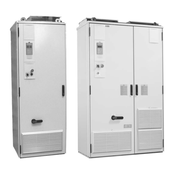
Hardware description What this chapter contains This chapter describes the hardware of the ACS800-17. Main components of the ACS800-17 Frame sizes R6i to R9i The main components of the drive (converter frame sizes R6i to R9i) are shown below. The control panels are optional. LCL Filter RDCU RMIO... -
Page 20: Auxiliary Control Unit
Drive section Braking sections Supply section Auxiliary ISU Supply Braking Unit Incoming Control Unit (optional) Unit Unit Common DC Bus RDCU RMIO FUN C D RIVE EN TER L O C RESET R EF R EM Inverter Supply Unit FUN C D RIVE EN TER L O C... -
Page 21: Example
• DC fuses (not for all inverter sizes) • cabinet mechanics. Example A block diagram of a R11i drive section is shown below. Inverter: Phase Modules Drive Optional Section Motor Inverter The inverter includes an IGBT output bridge which forms controlled a.c. voltage from the intermediate circuit d.c. - Page 22 • power supply board for gate drivers (NGPS) in V-phase module • power supply board (NPOW-62) in V-phase module. Control board interconnection (frame sizes R6i to R9i) RDCU RDCU RMIO RMIO NINT NINT Power plate Two NGDR boards control one power U, V, W plate phase...
-
Page 23: Power Plate
Power plate This photo shows one power plate with the NGDR boards connected. NGDR board + terminal Power plate terminal Insulated base plate Main circuit diagram Frame size R8i/R9i Frame R8i/R9i contains three phase modules, each producing one of the three phases driving the motor. - Page 24 Frame size R12i Frame R12i contains three phase modules, each producing one of the three phases driving the motor. Each phase module consists of three parallel connected power plates. Six IGBTs with free wheeling diodes are integrated to a single power plate. The figure below shows the connection of one phase.
-
Page 25: Voltages From The Supply Section
Voltages from the supply section The supply section supplies the inverter via the DC busbar. The inverter also takes energy from the DC busbar to make control voltages for the control boards and auxiliary voltage for I/O board. Voltage for the inverter cooling fans is taken from a 230/115 V a.c. transformer (in the Auxiliary Control Unit) via thermal protection switch. - Page 26 Hardware description...
-
Page 27: Mechanical Installation
Mechanical installation What this chapter contains This chapter provides instructions for moving the shipping splits, fastening them to the floor and joining them together. Instructions concerning only some types are marked. General See chapter Technical data for allowed operating conditions and requirements for free space around the unit. -
Page 28: Cabinet Construction
Cabinet construction In marine versions, the cabinet includes, in addition, vibration dampers and handles on the doors. Cabinet door opening Marine Applications (ACS 800 MarineDrive) ACS800-17 ACS800-17 frame size R7i frame size R9i Mechanical installation... -
Page 29: Moving Of The Shipping Split
Moving of the shipping split by crane Use the steel lifting lugs attached to the top of the cabinets. Insert the lifting ropes or slings into the holes of the lifting lugs. The lifting lugs can be removed (not mandatory) once the cabinets are in their final location. -
Page 30: By Fork-Lift
by fork-lift The centre of gravity may be quite high. Be therefore careful when transporting the shipping splits. Tilting of the cabinets must be avoided. Moving of the shipping split is to be done only with the cabinets upright. by split rollers (not allowed in marine versions) Remove the bottom wooden frame which is part of the shipment. -
Page 31: Final Placement Of The Shipping Splits
Final placement of the shipping splits Marine units: WARNING! Marine units are equipped with vibration dampers below the cabinets which may be damaged when moving. Be careful when moving the cabinets. The cabinets can be moved into their final position by using an iron bar and a wooden piece at the bottom edge of the cabinet. -
Page 32: Working Order Of The Mechanical Installation
Working order of the mechanical installation • Fasten the first shipping split to the floor with fastening clamps or through the holes inside the 100 mm from wall cabinet. See section Fastening the shipping split to the floor (non-marine units). In marine versions, fasten the first shipping split to the floor and roof/wall as described in section Fastening the shipping splits to the floor and wall... -
Page 33: Fastening The Shipping Split To The Floor (Non-Marine Units)
Fastening the shipping split to the floor (non-marine units) Fastening the shipping split to the floor is especially important in installations subjected to vibration or other movement. Fastening clamps Insert the clamp into the longitudinal hole in the edge of the cabinet frame body and fasten it with a bolt to the floor. -
Page 34: Holes Inside The Cabinet
Holes inside the cabinet The cabinet can be fastened to the floor using the fastening holes inside the cabinet, if they are available and accessible. The maximum allowed distance between the fastening points is 800 mm. Fastening holes inside the cabinet Side plates of the cabinet: 15 mm Back plate of the cabinet: 10 mm... -
Page 35: Fastening The Shipping Splits To The Floor And Wall (Marine Units)
Fastening the shipping splits to the floor and wall (marine units) The shipping split must be fastened to the floor and roof (wall) in marine versions as follows. Fasten the shipping split to the floor with M10 or M12 bolts through the holes in the vibration damper flat bar. -
Page 36: Joining The Shipping Splits
Joining the shipping splits Shipping splits are joined in the busbar joining section. Special screws (M6) for fastening the cabinets together are enclosed in a plastic bag inside the last cabinet of the shipping split. The threaded bushings are already mounted on the post. Threaded bushing Working order Maximum tightening torque... -
Page 37: Connecting The Dc Busbar And The Pe Busbar
• 200 mm wide joining section: Remove the intermediate plate hiding the back posts in the joining section. 600 mm wide joining section: Remove the partitioning plates. Partitioning plate Intermediate plate Busbar joining Back posts accessible section • Fasten the back post of the joining section with seven screws (below the busbar joining part) to the post of the next cabinet. - Page 38 DC busbar The DC busbar connection is shown below. Joint pieces Tighten the bolts with a torque wrench to 55–70 Nm (40–50 ft.-lbs.) Side view of single busbar connection PE busbar The PE busbar connection is shown below. Joint piece Tightening torque: 35–40 Nm (25–30 ft.-lbs.)
-
Page 39: Lifting A Double Roof
Lifting a double roof When the drive is equipped with a double roof: • Lift the upper part of the roof plate up from the transportation position. • Lock the roof to its final position with the M6 screws. Mechanical installation... -
Page 40: Miscellaneous
Miscellaneous Cable conduit in the floor below the cabinet A cable conduit can be constructed below the 400 mm wide middle part of the cabinet. The cabinet weight lies on the two 100 mm wide transverse sections which the floor must carry. Side view Viewed from above With heavy... -
Page 41: Electric Welding
Electric welding It is not recommended to fasten the cabinet by welding. Cabinets without vibration dampers If the preferred fastening methods (clamps or holes inside the cabinet) can not be used, proceed as follows: • Connect the return conductor of the welding equipment low to the cabinet frame within 0.5 metres of the welding point. - Page 42 Mechanical installation...
-
Page 43: Planning The Electrical Installation
Always follow local regulations. Note: If the recommendations given by ABB are not followed, the drive may experience problems that the warranty does not cover. -
Page 44: Checking The Compatibility Of The Motor
The stress on motor insulation can be avoided by using optional ABB du/dt filters. du/dt filters also reduce bearing currents. Planning the electrical installation... -
Page 45: Requirements Table
Requirements table The following table shows how to select the motor insulation system and when optional ABB du/dt limitation, insulated N-end (non-driven end) motor bearings and ABB common mode filters are required. The motor manufacturer should be consulted regarding the construction of the motor insulation and additional requirements for explosion-safe (EX) motors. - Page 46 Motor type Nominal mains Requirement for voltage (AC line Motor insulation ABB du/dt limitation, insulated N-end bearing and ABB common voltage) system mode filter < 100 kW 100 kW < P < 350 kW > 350 kW frame size > IEC 315 frame size <...
- Page 47 If voltage is raised by the drive, select the motor insulation system according to the increased intermediate circuit DC voltage level, especially in the 500 V (+10%) supply voltage range. Note 6: ABB motors of types other than M2_, M3_, HX_ and AM_ Select according to non-ABB motors.
-
Page 48: Permanent Magnet Synchronous Motor
Permanent magnet synchronous motor Only one permanent magnet motor can be connected to the inverter output. Install a safety switch between a permanent magnet synchronous motor and the motor cable. The switch is needed to isolate the motor during any maintenance work in the drive. -
Page 49: Emergency Stop Devices
The EMC filter (if present) includes capacitors connected between the main circuit and the frame. These capacitors and long motor cables increase the earth leakage current and may cause fault current circuit breakers to function. Emergency stop devices For safety reasons, install the emergency stop devices at each operator control station and at other operating stations where emergency stop may be needed. -
Page 50: Prevention Of Unexpected Start
Prevention of unexpected start The drive can be equipped with an optional prevention of unexpected start function according to standards EN 292-1: 1991; EN 292-2: 1991 + A1, 1995; EN 954-1: 1996; EN 60204-1-1: 1992 + Corr. 1993; and EN 1037: 1995. The function is achieved by disconnecting the control voltage to the power semiconductors of the inverters of the drive. -
Page 51: Alternative Power Cable Types
A four-conductor system is allowed for input cabling, but shielded symmetrical cable is recommended. To operate as a protective conductor, the shield conductivity must be as follows when the protective conductor is made of the same metal as the phase conductors: Cross-sectional area of the phase Minimum cross-sectional area of the... -
Page 52: Motor Cable Shield
Motor cable shield To effectively suppress radiated and conducted radio-frequency emissions, the shield conductivity must be at least 1/10 of the phase conductor conductivity. The requirements are easily met with a copper or aluminium shield. The minimum requirement of the motor cable shield of the drive is shown below. It consists of a concentric layer of copper wires with an open helix of copper tape. -
Page 53: Power Factor Compensation Capacitors
Power factor compensation capacitors Do not connect power factor compensation capacitors or surge absorbers to the motor cables (between the drive and the motor). They are not designed to be used with drives, and will degrade motor control accuracy. They can cause permanent damage to the drive or themselves due to the rapid changes in the drive output voltage. -
Page 54: Relay Output Contacts And Inductive Loads
Relay output contacts and inductive loads Inductive loads (such as relays, contactors, motors) cause voltage transients when switched off. The relay contacts of the RMIO board are protected with varistors (250 V) against overvoltage peaks. In spite of this, it is highly recommended to equip inductive loads with noise attenuating circuits (varistors, RC filters [AC] or diodes [DC]) in order to minimize the EMC emission at switch-off. -
Page 55: Selecting The Control Cables
Control panel cable In remote use, the cable connecting the control panel to the drive must not exceed 3 metres (10 ft). The cable type tested and approved by ABB is used in control panel option kits. Coaxial cable (for use with Advant Controllers AC 80/AC 800) •... -
Page 56: Connection Of A Motor Temperature Sensor To The Drive I/O
Connection of a motor temperature sensor to the drive I/O WARNING! IEC 60664 requires double or reinforced insulation between live parts and the surface of accessible parts of electrical equipment which are either non- conductive or conductive but not connected to the protective earth. To fulfil this requirement, the connection of a thermistor (and other similar components) to the digital inputs of the drive can be implemented in three alternate ways:... -
Page 57: Control Cable Ducts
Control cable ducts 24 V 230 V 24 V 230 V Not allowed unless the 24 V Lead 24 V and 230 V control cables in separate ducts inside cable is insulated for 230 V or the cabinet. insulated with an insulation sleeving for 230 V. - Page 58 Planning the electrical installation...
-
Page 59: Electrical Installation
Electrical installation WARNING! Only qualified electricians are allowed to carry out the work described in this chapter. Follow the Safety instructions on the first pages of this manual. Ignoring the safety instructions can cause injury or death. What this chapter contains This chapter describes the electrical installation of the drive. -
Page 60: Input Power Cable Wiring Diagrams
Input power cable wiring diagrams This section describes the input power cable connections of the drive. The following Motor cable wiring diagrams section provides some basic instructions for the routing and mechanical connection of cables. The mechanical cable connections are basically the same, whether for the incoming supply or an inverter;... -
Page 61: High Power Supply
High power supply Busbar connection A high current (> 300 A) busbar connection is represented below. Metal conduit (shield) Transformer Converter L1 L2 L3 N 1) Connect the metal conduit of the busbar system (or the metal of the bus duct) to PE at either one end or both ends. - Page 62 Single-core cables with concentric protective shields When single-core cables equipped with concentric protective shields (metal) are used, the phase current will induce voltage to the cable shield. If the shields are connected to each other at both ends of the cable, current will flow in the cable shield.
-
Page 63: Motor Cable Wiring Diagrams
Motor cable wiring diagrams Motor cable connections for different cable types are represented below. For minimum radio frequency interference (RFI) at the motor end, earth the cable shield 360 degrees at the lead-through or earth the cable by twisting the shield (flattened width >... -
Page 64: Single Inverters
Single inverters Motor cable connections with parallel symmetrical cables are represented below. Inverter OUTPUT 1 2 3 1 2 3 1 2 3 1 2 3 1 2 3 1 2 3 Electrical installation... -
Page 65: Location Of Power Cable Terminals (R6I, R7I)
Location of power cable terminals (R6i, R7i) The cable connections of a bottom entry unit of frame size R7i are represented below. In frame size R6i, the terminals are located similarly. Isolated stud terminals Busbars for input cable connection: L1, L2, L3. for motor cable connection: PE terminal U2, V2, W2. -
Page 66: Location Of Power Cable Terminals (R8I, R9I)
Location of power cable terminals (R8i, R9i) The cable connections of a bottom entry unit of frame size R9i are represented below. In frame size R8i, the terminals are located similarly. Bottom entry unit Top entry unit Busbars for input and motor cable connection RMIO Busbars for input... -
Page 67: Location Of Motor Cable Terminals (R11I And R12I Bottom Entry)
Location of motor cable terminals (R11i and R12i bottom entry) The cable connections of a bottom entry unit of frame size R11i are represented below. In frame size R12i, the terminals are located similarly. The input cables are lead via the Incoming Unit. To gain access to the motor cable terminals, remove the cooling fans as follows: 4. -
Page 68: Location Of Motor Cable Terminals (R11I And R12I Top Exit)
Location of motor cable terminals (R11i and R12i top exit) This cubicle is used for • motor cable entry and exit through the top of the cabinet Cable entry from the bottom is shown below. The top entry is accomplished in the same way except that cables are entering or exiting the cabinet from the top. -
Page 69: About Power Cable Busbars And Use Of Cable Lugs
About power cable busbars and use of cable lugs A view of power cable busbars of large drive units is shown below. If necessary, the same screw can be used for connecting two cable lugs (on both sides of the busbar). Cable lugs with one or two holes can be used. -
Page 70: Use Of Conductive Sleeves Of Power Cable Lead-Throughs
Use of conductive sleeves of power cable lead-throughs ° Conductive sleeves are supplied by ABB as an option to provide 360 high- frequency earthing for motor cables. Follow these instructions: • If fire insulation is used, make an opening to the mineral wool sheet according to the diameter of the cable. -
Page 71: Use Of Common Mode Filters On The Motor Cable
Use of common mode filters on the motor cable If common mode filter or light common mode filter is required (see Planning the electrical installation Checking the compatibility of the motor Requirements table), lead the motor cable phase conductors through the toroidal cores as follows: •... -
Page 72: Control Cable Connections At Shipping Split Joints
Control cable connections at shipping split joints Some control wires are chained through the shipping splits. 230/115 V voltage transformer, uninterrupted power supply (UPS) and emergency stop wires are chained via terminal blocks X25 at the upper left hand corner of the fields next to the busbar joining sections. -
Page 73: External Control Cable Connections
(Code: 64735501 [English]), available through ABB representatives. EMC earthing at the cable entry ° high frequency earthing of the control cable shield at the cable entry is available as an option from ABB (figure below). Side view Top view Lead-through plate... - Page 74 Special for top entry When each cable has its own rubber grommet, sufficient IP and EMC protection can be achieved. However, if very many control cables come to one cabinet, plan the installation beforehand as follows: • Make a list of the cables coming to the cabinet. •...
- Page 75 Bottom and top entry Proceed as follows: • Loosen the lead-through plate position screws. Pull the two parts apart. • Bottom entry Lead the cable inside the cabinet through the EMI conductive cushions. Top entry Lead the cable inside the cabinet through the grommet and the EMI conductive cushions.
- Page 76 • Top entry: If more than one cable go through a grommet, the grommet must be sealed by Loctite 5221 (catalogue number 25551). Side view Apply Loctite 5221 inside the grommet. Connect the earthing wire to Attach control the PE busbar. cables to the supporting plate.
-
Page 77: Installation Of Optional Modules And Pc
Installation of optional modules and PC The optional module (such as fieldbus adapter, I/O extension module and the pulse encoder interface) is inserted in the optional module slot of the RMIO board and fixed with two screws. See the appropriate optional module manual for cable connections. -
Page 78: Fibre Optic Link
Pulse encoder module cabling Note1: If the encoder is of unisolated CHASSIS type, ground the encoder cable at the RTAC-01 PULSE ENCODER INTERFACE drive end only. If the encoder is SHLD SHLD galvanically isolated from the motor CHA+ CHA- shaft and the stator frame, ground the CHB+ INIT CHB-... -
Page 79: Motor Control And I/O Board (Rmio)
Motor control and I/O board (RMIO) What this chapter contains This chapter shows • external control connections to the RMIO board for the the ACS 800 Standard Application Program (Factory Macro) • specifications of the inputs and outputs of the board. To which products this chapter applies This chapter applies to ACS800 units which employ the RMIO board. -
Page 80: External Control Connections (Non-Us)
External control connections (non-US) External control cable connections to the RMIO board for the ACS 800 Standard Application Program (Factory Macro) are shown below. For external control connections of other application macros and programs, see the appropriate Firmware Manual. Terminal block size - - - - 1 VREF- Reference voltage -10 VDC, 1 kohm <... -
Page 81: External Control Connections (Us)
External control connections (US) External control cable connections to the RMIO board for the ACS 800 Standard Application Program (Factory Macro US version) are shown below. For external control connections of other application macros and programs, see the appropriate Firmware Manual. Terminal block size - - - - 1 VREF-... -
Page 82: Rmio Board Specifications
RMIO board specifications Analogue inputs With Standard Application Program two programmable differential current inputs (0 mA / 4 mA ... 20 mA, R = 100 ohm) and one programmable differential voltage input (-10 V / 0 V / 2 V ... +10 V, R >... -
Page 83: Relay Outputs
Contact material Silver Cadmium Oxide (AgCdO) Isolation test voltage 4 kVAC, 1 minute DDCS fibre optic link With optional communication adapter module RDCO. Protocol: DDCS (ABB Distributed Drives Communication System) 24 VDC power input Voltage 24 VDC ± 10 %... - Page 84 Isolation and grounding diagram (Test voltage: 500 V AC) VREF- AGND VREF+ AGND AI1+ Common mode AI1- voltage between AI2+ channels ±15 V AI2- AI3+ AI3- AO1+ AO1- AO2+ AO2- Jumper J1 settings: DGND1 All digital inputs share a common ground.
-
Page 85: Installation Checklist
Installation checklist What this chapter contains This chapter represents the installation checklist. General It is advisable to go through the checklist below together with another person. The mechanical and electrical installation must be checked before start-up. Study carefully the Safety Instructions on the first pages of this manual before working on the unit. - Page 86 INSTALLATION CHECKLIST The appropriate DC fuses are installed. (See chapter Technical data.) The motor is of correct voltage. The motor star/delta connection at the motor terminal box is correct. Motor cable routing. Check that the toroidal cores are properly installed on the motor cable when a common mode filter is required. The motor connections at U2, V2 and W2 are OK.
-
Page 87: Start-Up
Start-up What this chapter contains This section describes the hardware commissioning of an ACS800-17 drive section. General Perform the drive section commissioning according to this section. For the drive control firmware commissioning, refer to the application program Firmware Manual. Perform the supply section commissioning according to the instructions given in the IGBT Supply Sections User’s Manual [3BFE 64013700 (English)]. -
Page 88: Checks With No Voltage Connected
Action Information Checks with no voltage connected WARNING! Ensure that the disconnector of the supply transformer is locked to open position, i.e. no voltage is, or can be connected to the drive inadvertently. Check also by measuring that no voltage is actually connected. If the motor has a safety switch, make sure that it is open. -
Page 89: Connecting Voltage To The Drive
Action Information Connecting voltage to the drive The possible supply disconnecting and switching options are shown below. See the circuit diagrams delivered with the unit for the actual connections (customized configurations). Switch fuse L1, L2, L3 Auxiliary voltage Switch fuse and contactor Air circuit breaker Auxiliary voltage... -
Page 90: Checks With Voltage Connected To The Drive Section
Action Information Checks with voltage connected to the drive section Set the drive parameters according to the application Firmware Manual. Check that the Prevention of Unexpected Start (if available) is working: See the circuit diagrams delivered with the device. - Stop the drive by a Stop command and wait until the drive has stopped. - Open the Prevention of Unexpected Start switch by opening the switch on the control desk: the circuit will open. -
Page 91: Preventive Maintenance
Preventive maintenance What this chapter contains This chapter represents how to maintain the drive in operational condition. General WARNING! The Safety Instructions on the first pages of this manual must be followed. Negligence of these instructions can cause injury or death. If installed in an appropriate environment, the drive requires very little maintenance. -
Page 92: Spare Modules
Capacitor failure is usually followed by a mains fuse failure or a fault trip. Contact ABB if capacitor failure is suspected. Replacements are available from ABB. Do not attempt operation with other than ABB specified spare parts. - Page 93 Reforming time (hours) Non-operational time (years) Method 1 Method 2 Figure 1. Capacitor reforming time for Method 1 and Method 2. Converters stocked (non-operational) for less than 2 years Switch the power on to the converter for a time given in Figure (Method 1).
- Page 94 or phase module L– Disconnect from W2 (W1) supply (1.35 ×U V2 (V1) U2 (U1) Converter Supply Voltage Recommended Components 380 V < U < 415 V SKD 82/16 220 Ohm / 700 W 22 nF / 2000 V 380 V < U <...
- Page 95 WARNING! The converter supply must be disconnected while the reforming circuit is connected. or phase module DC Power Supply L– Disconnect from W2 (W1) supply (1.35 ×U V2 (V1) U2 (U1) Converter * R = 100 Ohm / 500 W Preventive maintenance...
- Page 96 Preventive maintenance...
-
Page 97: Technical Data
Technical data What this chapter contains This chapter describes the technical data concerning the ACS800-17. Ratings The ratings for the ACS800-17 with 50 Hz and 60 Hz supplies are given below. Normal use Duty cycle 1/5min Duty cycle 10/60s I 2N I 2hd I 2hd I 2hd... -
Page 98: Output Current Temperature Derating
Normal Use Duty Cycle Rated rms output current (= maximum continuous Rated rms output current output current) Rated apparent output power Typical motor power. The power ratings in kW apply to most IEC 34 motors. The current ratings are the same regardless of the supply voltage within one voltage range. The rated current of the drive must be higher than or equal to the rated motor current to achieve the rated motor power given in the table. -
Page 99: Motor Connection
Switching frequency: 3 kHz Maximum recommended motor cable length: For cables longer than 500 metres / 1640 ft (cumulative length in case of parallel connected motors), an ABB representative must be consulted. With pulse encoder speed measurement, the maximum cable length is 300 m. With du/dt filters, refer to du/dt Filters Installation Guide [3AFE 58933368 (English)]. -
Page 100: Efficiency And Cooling Method
Motor bearings: Insulated bearing at the non-driven end is recommended. Cable types: The tables below give the copper and aluminium cable types for different load currents (I ). A correction factor of K = 0.70 has been used (max. 9 Lmax cables laid on a cable ladder side by side, three ladders on top of each other, ambient temperature 30 °C (86 °F), EN 60204-1 and IEC 364-5-523) -
Page 101: Ambient Conditions
At sites over 1000 m (3300 ft.) above sea level, the maximum output current is derated as follows. If the installation site is higher than 2000 m (6600 ft.) above sea level, please contact your local ABB distributor or office for further information. -
Page 102: Fuses
Fuses Only ultra rapid fuses guarantee proper protection for the rectifier semiconductors. AC fuses The a.c. fuses (Bussmann) used in the ACS800-17 supply sections are listed below. Fuse Pre- Frequency Frame Supply section arching converter type size type Type Size integral Supply voltage 400V IGBT supply ACS800-17-0120-3 R7i... -
Page 103: Igbt Supply Unit Dc Fuses
IGBT supply unit DC fuses The d.c. fuses (Bussmann) used in the IGBT supply units are listed below. IGBT Supply IGBT Supply Size Type Size Type Section Frame Section Frame Type Type 415 V and 500 V Range 690 V Range R11i 660V 1000... -
Page 104: Connection Holes
Connection holes The connection holes for mains and motor cable lugs are given below. Holes for cable Number of cable Bottom plate Number of cable Frame Supply section lugs per phase entries at bottom opening entries at top Drive type size type (diameter 60 mm) -
Page 105: Cabinet
Cabinet Below are the cabinets, degrees of protection and free space requirements. Degree of Space Space Space on Space in Protection above below left/right front/back IP 21, IP 22, IP 200/100 42, IP 54, IP 54 R IP 21 = standard, R = air outlet duct 200 between cabinets when installed back to back Door opening Technical data... -
Page 106: Cooling Air, Dimensions
Cooling air, dimensions This table gives the depth of the cabinet. The height of the switch fuse handle is 45 mm from the cabinet door. Depth Depth of the frame Depth of the roof Depth including the door, the frame and the back plate Depth including the door, the frame, the back plate and the flash barrier Added depth including air circuit breaker spacer frame... -
Page 107: Air Flow Requirements
Air flow requirements Below are cooling air flow requirements, heat losses, dimensions and weights of ACS800-17. IGBT supply Drive section Air flow Heat loss Width Weight Drive type Frame Frame [kW] [mm] [kg] Section type Module type Module type size size Supply voltage 400V IGBT supply ACS800-17-0120-3 R7i... -
Page 108: Noise
Noise The noise values of the ACS800-17 units are given below. Noise Noise Noise Type Type Type (dB) (dB) (dB) ACS800-17-0120-3 ACS800-17-0100-5 ACS800-17-0120-6 ACS800-17-0185-3 ACS800-17-0140-5 ACS800-17-0205-6 ACS800-17-0225-3 ACS800-17-0215-5 ACS800-17-0255-6 ACS800-17-0265-3 ACS800-17-0255-5 ACS800-17-0315-6 ACS800-17-0335-3 ACS800-17-0325-5 ACS800-17-0375-6 ACS800-17-0405-3 ACS800-17-0395-5 ACS800-17-0485-6 ACS800-17-0630-3 ACS800-17-0495-5 ACS800-17-0750-6 ACS800-17-0765-3 ACS800-17-0770-5... -
Page 109: Transportation
The DC capacitors of the unit contain electrolyte which is classified as hazardous waste. They must be removed and handled according to local regulations. For further information on environmental aspects, please contact your local ABB distributor. CE marking... -
Page 110: Compliance With The Emc Directive
Equipment 2. An EMC plan for preventing disturbances is drawn up for the installation. A template is available from the local ABB representative. 3. The motor and control cables are selected as specified in the Hardware Manual. 4. The drive is installed according to the instructions given in the Hardware Manual. -
Page 111: Csa Marking
CSA marking The CSA marking is often required in North America. CSA marked ACS800-17 drives are available on request up to 600 V. The drive is suitable for use in a circuit capable of delivering not more than 65 kA rms symmetrical amperes at 600 V maximum. -
Page 112: Compliance With Iec 61800-3
In no event shall the manufacturer, its suppliers or subcontractors be liable for special, indirect, incidental or consequential damages, losses or penalties. If you have any questions concerning your ABB drive, please contact the local distributor or ABB office. The technical data, information and specifications are valid at the time of printing. The manufacturer reserves the right to modifications without prior notice. -
Page 113: Dimensional Drawings
Dimensional drawings What this chapter contains This chapter contains the dimensional drawings of ACS800-17 frame sizes R6i to R12i. Dimensional drawings... - Page 114 Dimensional drawings...
- Page 115 Dimensional drawings...
- Page 116 Dimensional drawings...
- Page 117 Dimensional drawings...
- Page 118 Dimensional drawings...
- Page 119 Dimensional drawings...
- Page 120 Dimensional drawings...
- Page 121 Dimensional drawings...
- Page 122 Dimensional drawings...
- Page 124 ABB Oy ABB Inc. AC Drives Drives and Power Electronics 16250 West Glendale Drive P.O. Box 184 New Berlin, WI 53151 FIN-00381 HELSINKI FINLAND Telephone 262 785-3200 Telephone +358 10 22 11 800 243-4384 Telefax +358 10 22 22681 Telefax...