
Related Manuals for ASROCK NUC-1215U


Summary of Contents for ASROCK NUC-1215U
- Page 1 NUC-1215U NUC-1215UE NUC-1235U NUC-1245UE NUC-7305 NUC-1265UE NUC-1255U User Manual Version 1.0 Published March 2022 Copyright©2022 ASRockind INC. All rights reserved.
- Page 2 Version 1.0 Published March 2022 Copyright©2022 ASRockind INC. All rights reserved. Copyright Notice: No part of this documentation may be reproduced, transcribed, transmitted, or translated in any language, in any form or by any means, except duplication of documentation by the purchaser for backup purpose, without written consent of ASRockind Inc.
- Page 3 ® The terms HDMI and HDMI High-Definition Multimedia Interface, and the HDMI logo are trademarks or registered trademarks of HDMI Licensing LLC in the United States and other countries. CAUTION: RISK OF EXPLOSION IF BATTERY IS REPLACED BY AN INCORRECT TYPE. DISPOSE OF USED BATTERIES ACCORDING TO THE INSTRUCTIONS.
-
Page 4: Table Of Contents
Contents 1 Introduction ............5 1.1 Package Contents ............5 1.2 Specifications ..............6 1.3 Motherboard Layout ............8 1.4 I/O Panel ................ 9 2 Installation ............10 2.1 Screw Holes ..............10 2.2 Pre-installation Precautions ........... 10 2.3 Installation of Memory Modules (SO-DIMM) ....11 2.4 Expansion Slots ............ -
Page 5: Introduction
Chapter 1: Introduction Thank you for purchasing ASRockind NUC-1215U / NUC-1215UE / NUC-1235U / NUC-1245UE / NUC-7305 / NUC-1265UE / NUC-1255U motherboard, a reliable motherboard produced under ASRockind’s consistently stringent quality control. It delivers excellent performance with robust design conforming to ASRockind’s com- mitment to quality and endurance. -
Page 6: Specifications
Gen (Alder Lake-P) Core™ Processors NUC-1265UE (i7-1265UE) NUC-1245UE (i5-1245UE) NUC-1215UE (i3-1215UE) Processor NUC-1255U (i7-1255U) System NUC-1235U (i5-1235U) NUC-1215U (i3-1215U) NUC-7305 (Celeron-7305) Chipset BIOS AMI SPI 256 Mbit Technology Dual Channel DDR4 3200 MHz Memory Capacity 64GB (32 GB per DIMM) - Page 7 HDMI 1 x HDMI 2.0b DisplayPort 1 x DP 1.4a Rear I/O Ethernet 2 x 2.5 Gigabit LAN 2 x USB 3.2 Gen2 (Type A) DC Jack 2 x USB 2.0 (1 x 2.00 pitch header) Internal 1 x COM(RS-232/422/485) Connector TPM 2.0 onboard IC 1 x M.2 (KEY M, 2242/2260/2280) with...
-
Page 8: Motherboard Layout
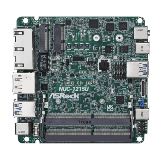
1.3 Motherboard Layout 1 : M.2 Key-M Socket (M2_M1) 2 : M.2 Key-E Socket (M2_E1) 3 : USB2.0 Connector (USB2_7_8) 4 : COM Port Header (RS-232/422/485) 5 : SATA3 Port (SATA3_0) 6 : JP1 7 : System Panel Header (PANEL1) Back Side : Power Button (PWR_BTN1) Fan Connector (FAN1) -
Page 9: I/O Panel
1.4 I/O Panel Front I/O: Rear I/O: USB3/DP Type-C Port (TC_UD1) RJ-45 LAN Port (LAN2)* USB 3.2 Gen2 Ports (USB3_3_4) Top : DisplayPort (DP1) Thunderbolt Type-C Port (TC_T0) Bottom : HDMI Port (HDMI1) Audio Jack (AUDIO1) USB 3.2 Gen2 Ports (USB3_1_2) RJ-45 LAN Port (LAN1)* DC-In Jack (DC_IN1) * There are two LED next to the LAN port. -
Page 10: Installation
Chapter 2: Installation Before you install the motherboard, study the configuration of your chassis to ensure that the motherboard fits into it. Make sure to unplug the power cord before installing or removing the motherboard. Failure to do so may cause physical injuries to you and damages to motherboard components. -
Page 11: Installation Of Memory Modules (So-Dimm)
2.3 Installation of Memory Modules (SO-DIMM) This motherboard rovides two 204-pin DDR4 (Double Data Rate 4) SO-DIMM slots. Step 1. Align a SO-DIMM on the slot such that the notch on the SO-DIMM matches the break on the slot. 1. The SO-DIMM only fits in one correct orientation. It will cause permanent damage to the motherboard and the SO-DIMM if you force the SO-DIMM into the slot at incorrect orientation. -
Page 12: Expansion Slots
2.4 Expansion Slots (M.2 Slots) There are 2 M.2 slots on this motherboard. M.2 for SSD: 1 x M.2 (KEY M, 2242/2260/2280) with PCIe Gen4 x4 for SSD. * M.2 Key M 2280 (Supported by bracket) M.2 for Wi-Fi: 1 x M.2 (Key E, 2230) with PCIe x1, USB 2.0 and CNVi for Wireless. M.2 Key-M Socket (M2_M1) M.2 Key-E Socket (M2_E1) PERn0... -
Page 13: Onboard Headers And Connectors
2.5 Onboard Headers and Connectors Onboard headers and connectors are NOT jumpers. Do NOT place jumper caps over these headers and connectors. Placing jumper caps over the headers and connectors will cause permanent damage of the motherboard! SATA3 Connector This Serial ATA3 (SATA3) connector supports SATA data (SATA3_0: see p.8, No. - Page 14 RESET (Reset Switch): Connect to the reset switch on the chassis front panel. Press the reset switch to restart the computer if the computer freezes and fails to perform a normal restart. PLED (System Power LED): Connect to the power status indicator on the chassis front panel. The LED is on when the system is operating.
- Page 15 Back Side: Power Button Header (PWR_BTN1) Fan Connector +12V (FAN1) FAN_SPEED FAN_SPEED_CONTROL Battery Connector (BAT1) ESPI Connector (ESPI1)
-
Page 16: Installation Of Rom Socket
2.6 Installation of ROM Socket * Do not apply force to the actuator cover after ic inserted. * Do not apply force to actuator cover when it is opening over 120 degree, Otherwise, the actuator cover may be broken. * The yellow dot (Pin1) on the ROM must be installed at pin1 position of the socket. -
Page 17: Uefi Setup Utility
Chapter 3: UEFI SETUP UTILITY 3.1 Introduction This section explains how to use the UEFI SETUP UTILITY to configure your system. The UEFI chip on the motherboard stores the UEFI SETUP UTILITY. You may run the UEFI SETUP UTILITY when you start up the computer. Please press <F2>... -
Page 18: Navigation Keys
3.1.2 Navigation Keys Please check the following table for the function description of each navigation key. Navigation Key(s) Function Description Moves cursor left or right to select Screens Moves cursor up or down to select items + / - To change option for the selected items <Enter>... -
Page 19: Advanced Screen
3.3 Advanced Screen In this section, you may set the configurations for the following items: CPU Configu- ration, Chipset Configuration, Storage Configuration, Super IO Configuration, AMT Configuration, ACPI Configuration, USB Configuration and Trusted Computing. Setting wrong values in this section may cause the system to malfunction. -
Page 20: Cpu Configuration
3.3.1 CPU Configuration Intel Hyper Threading Technology Intel Hyper Threading Technology allows multiple threads to run on each core, so that the overall performance on threaded software is improved. Active Processor P-Cores Select the number of cores to enable in each processor package. Active Processor E-Cores Select the number of E-Cores to enable in each processor package. - Page 21 Intel Turbo Boost Technology Use this item to enable or disable Intel Turbo Boost Mode Technology. Turbo Boost Mode allows processor cores to run faster than marked fre- quency in specific conditions. The default value is [Enabled]. CPU Thermal Throttling You may select [Enabled] to enable CPU internal thermal control mechanism to keep the CPU from overheating.
-
Page 22: Chipset Configuration
3.3.2 Chipset Configuration VT-d ® ® Use this to enable or disable Intel VT-d technology (Intel Virtualization Technology for Directed I/O). The default value of this feature is [Disabled]. Share Memory Configure the size of memory that is allocated to the integrated graphics processor when the system boots up. -
Page 23: Storage Configuration
3.3.3 Storage Configuration SATA Controller(s) Use this item to enable or disable the SATA Controller feature. SATA Mode Selection Use this to select SATA mode. The default value is [AHCI Mode]. AHCI (Advanced Host Controller Interface) supports NCQ and other new features that will improve SATA disk perfor- mance but IDE mode does not have these advantages. -
Page 24: Super Io Configuration
3.3.4 Super IO Configuration COM1 Configuration Use this to set parameters of COM1. Type Select Use this to select COM1 port type: [RS232], [RS422] or [RS485]. WDT Timeout Reset Use this to set the Watch Dog Timer. -
Page 25: Amt Configuration
3.3.5 AMT Configuration USB Provisioning of AMT Use this to enable or disable AMT USB Provisioning. The default is [Dis- abled]. MAC Pass Through Use this to enable or disable MAC Pass Through. The default is [Disabled]. Activate Remote Assistance Process Trigger CIRA boot. - Page 26 OCR PBA Boot Use this to enable or disable One Click Recovery PBA Boot. The default is [Enabled]. OCR Windows Recovery Boot Use this to enable or disable One Click Recovery Windows Recovery Boot. The default is [Enabled]. OCR Disable Secure Boot Use this to allows CSME to request Secure Boot to be disabled for One Click Recovery.
-
Page 27: Acpi Configuration
3.3.6 ACPI Configuration Suspend to RAM Use this item to select whether to auto-detect or disable the Suspend-to- RAM feature. Select [Auto] will enable this feature if the OS supports it. Onboard LAN Power On Use this item to enable or disable onboard LAN to turn on the system from the power-soft-off mode. -
Page 28: Usb Configuration
3.3.7 USB Configuration USB Power Control Use this item to control USB power. -
Page 29: Trusted Computing
3.3.8 Trusted Computing Security Device Support Enable or disable BIOS support for security device. -
Page 30: Hardware Health Event Monitoring Screen
3.4 Hardware Health Event Monitoring Screen In this section, it allows you to monitor the status of the hardware on your system, including the parameters of the CPU temperature, motherboard temperature, CPU fan speed, chassis fan speed, and the critical voltage. FAN1 Setting This allows you to set FAN1’s speed. -
Page 31: Security Screen
3.5 Security Screen In this section, you may set, change or clear the supervisor/user password for the system. Supervisor Password Set or change the password for the administrator account. Only the ad- ministrator has authority to change the settings in the UEFI Setup Utility. Leave it blank and press enter to remove the password. -
Page 32: Boot Screen
3.6 Boot Screen In this section, it will display the available devices on your system for you to config- ure the boot settings and the boot priority. Boot From Onboard LAN Use this item to enable or disable the Boot From Onboard LAN feature. Setup Prompt Timeout This shows the number of seconds to wait for setup activation key. -
Page 33: Exit Screen
3.7 Exit Screen Save Changes and Exit When you select this option, it will pop-out the following message, “Save configuration changes and exit setup?” Select [OK] to save the changes and exit the UEFI SETUP UTILITY. Discard Changes and Exit When you select this option, it will pop-out the following message, “Discard changes and exit setup?”... -
Page 34: Software Support
Chapter 4: Software Support 4.1 Install Operating System ® ® This motherboard supports various Microsoft Windows operating systems: 11 64-bit / 10 64-bit. Because motherboard settings and hardware options vary, use the setup procedures in this chapter for general reference only. Refer your OS docu- mentation for more information.