
Related Manuals for Bosch GC7000WP 50 23


Summary of Contents for Bosch GC7000WP 50 23
- Page 1 Installation and Maintenance Instructions Wall mounted gas condensing boilers Condens 7000 WP GC7000WP 50 23, GC7000WP 65 23, GC7000WP 85 23, GC7000WP 100 23...
-
Page 2: Table Of Contents
Table of contents Overview of plug-in strip ......19 Table of contents Connecting electrical components ....20 Connecting the pump of the pump assembly. - Page 3 Explanation of symbols and safety instructions instructions may result in material damage and 11.1.3 Faults that are not displayed .....44 personal injury, including danger to life.
-
Page 4: Product Information
▶ Keep the combustion air supply free of dust. The complete text of the Declaration of Conformity is available on the H Installation, commissioning and maintenance Internet: worcester-bosch.co.uk. Installation, commissioning and maintenance may be Product data for energy consumption performed only by an approved contractor. -
Page 5: Appliance Types
Appliance types 2.10 Frost protection Appliance type: Country Part No. NOTICE GC7000WP 50 23 UK, IE 7736 702 194 Installation damage due to the effects of frost. GC7000WP 65 23 UK, IE 7736 702 195 The heating system could freeze during a hard frost due to: mains voltage... -
Page 6: Product Overview
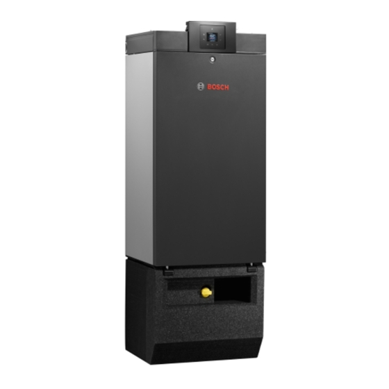
Product Information 2.11 product overview 0010030188-002 Fig. 1 GC7000WP with connection set on frame Condens 7000 WP – 6721841195 (2022/01) - Page 7 Product Information CWallondensing boiler: Pump assembly Gas line Drain pan heat exchanger Snap fastener Automatic air vent valve adjusting screw Air intake pipe Venturi nozzle [10] Air/gas ratio control valve [11] Remote control [12] On/off switch [13] Flue gas temperature sensor [14] Connector [15] Test point for flue gas routing [16] Test point for air supply...
-
Page 8: Dimensions
Product Information 2.12 Dimensions Boiler on frame Boiler against the wall 457.5 642,5 0010030944-002 0010031061-002 Fig. 2 Dimensions on base frame [mm] Fig. 3 Dimensions on the wall [mm] Condens 7000 WP – 6721841195 (2022/01) -
Page 9: Minimum Clearance From Walls
Product Information 2.13 Minimum clearance from walls Flue gas routing A [mm] B [mm] Ø 110 mm Connection adapter with elbow, A + 0.5*K horizontal flue outlet. Ø 110/ A + 0.5*K With a horizontal flue gas connection, make sure the electronic 160 mm components inside the boiler at the top remain accessible when placing Ø... -
Page 10: Opening And Closing The Front Panel Of The Appliance
Regulations 2.15 Opening and closing the front panel of the appliance NOTICE The boiler has a rotary lock. Risk of system damage due to differing operating conditions! ▶ Use the designated tool when opening and closing the front panel Faults may arise if the specified operating conditions are disregarded. (ideally a flat-bladed screwdriver). -
Page 11: Preconditions For Installation
Preconditions for installation Installation location Preconditions for installation NOTICE DANGER Frost damage! Danger to life from explosion! ▶ Install the heating system in a frost-free room. An increased and permanent ammonia concentration may lead to stress corrosion cracking on brass (e.g.gas valves, union nuts). As a result, DANGER there is a risk of explosion from gas escaping. - Page 12 ▶ Avoid damaging the connections on the boiler at the top and The following water conditioning and water treatment measures have bottom. been approved for use by Bosch: ▶ Cover the flue outlet adapter of the boiler during assembly. Application Product name Max.
- Page 13 Installation ▶ Set up the frame so the marking [4] points forwards. 0010039423-001 Fig. 9 Secure the frame to the wall or floor ▶ Push the boiler onto the frame. The boiler is secured to the frame at the rear. If it has been secured correctly a "click"...
-
Page 14: Connecting On The Heating And Gas Side
Installation Assembly on the wall ▶ Align the boiler using a spirit level and adjusting screw on the rear. NOTICE If the boiler may be damaged if attached incorrectly. Use suitable fixing materials for the condition of the masonry and weight of the boiler. -
Page 15: Installing The Gas Valve
Installation 6.5.1 Installing the gas valve WARNING If the sealing is not carried out correctly gas may escape. The thread of the gas connection under the boiler must not be roughened. This could cause gas to escape. ▶ Comply with the country-specific regulations and standards in relation to the sealing agent used. -
Page 16: Mounting The Siphon
Installation Mounting the siphon ▶ Fill the boiler siphon with water. ▶ Mount the boiler siphon [1] with gasket [2]. ▶ Check whether the neck of the siphon is properly connected to the condensation catch pan. ▶ Tighten the union nut hand tight [4]. 0010033906-002 Fig. -
Page 17: Connecting The Gas Valve
Installation NOTICE Damage to appliance due to incorrect connection of safety equipment. When using service valves, all safety equipment must remain in operation when the service valves are closed. ▶ Mount the connection for the expansion vessel and safety valve directly under the boiler and above the service valves. -
Page 18: Connecting An Expansion Vessel
PCB. The wrist strap must be worn until the PCB has been placed inside its screened ▶ For more information, refer to worcester-bosch.co.uk or you will find packaging or has been connected inside the closed control cabinet. -
Page 19: Overview Of Plug-In Strip
Electrical connection Overview of plug-in strip 120/230 VAC 120/230 VAC 0010034531-001 Fig. 23 Overview of plug-in strip Symbol Function Description On/Off temperature control (volt free) ▶ Connect an On/Off temperature control. Request for heat via volt-free contact, closed = on, open = off. Modulation-controlled control unit and ▶... -
Page 20: Connecting Electrical Components
Without pump assembly: When using pump types other than those available from Bosch as accessories, the PWM signal cannot be used. The PWM connection in the pump terminal unit is then not used. On/Off operation applies for these pumps. -
Page 21: Connecting The 3-Way Valve 230 V (Accessory)
Electrical connection ▶ Close the pump terminal box: fold the pump terminal box up and Mounting the function module (accessory) press horizontally until it snaps into place. NOTICE EMC fault due to incorrect cable routing. If bus cables and power cables are routed in parallel there is a risk of EMC faults occurring. -
Page 22: Commissioning
Commissioning If the maximum burner runtime of 4000 hours in 2 years is likely to be Commissioning exceeded: ▶ Set Burner run time to 4000 hours. WARNING If the maximum burner runtime is likely to be less than 4000 hours: Escaping gas. -
Page 23: Setting Options For Air/Gas Ratio Control Valve
Commissioning Setting options for air/gas ratio control valve ▶ Switch off the appliance. Different air/gas ratio control valves are used depending on the rating ▶ Remove the front panel. of the boiler. The positions of the various test ports and adjusting ▶... -
Page 24: Measuring Of Co2 And Co (Full Load)
Commissioning Measuring of CO and CO (full load) Appliance type: Gas type Gas/air ratio percentage [Pa] The CO content in the flue gases must be less than 250 ppm (0.025 % GC7000WP 65 Natural gas H 9.3 ± 0.3 by volume) during combustion without excess air. If the CO content (G20) exceeds 250 ppm, this will be due to pollution of the burner, malfunction Natural gas L... -
Page 25: Check The (Flue) Gas Tightness
Operation Check the (flue) gas tightness ▶ Draw attention to the dangers associated with carbon monoxide (CO) and recommend the use of CO detectors. NOTICE ▶ Hand over the technical documents to the operator. Damage to wall mounted boiler due to short circuit. ▶... -
Page 26: Siphon Filling Program
Operation Siphon filling program The siphon filling program is activated automatically, manually by the installer on the device or on the controller. Before starting, fill the condensate siphon ( Page 16). The siphon filling program is activated in the service menu under > Settings >... - Page 27 Operation Overview of the service menu – Pump Info – Pump ctr. mode – Min. output – Current status – Pump overrun – Current fault – Min. Sys. Pres. – Fault history – Target Sys. Pres. – Boiler – Special function –...
- Page 28 Operation Menu Info Meu item Settings/adjustment range Remark/restriction Tab. 11.1.2, page 39 Current status – Tab. 11.1.2, page 39 Current fault – Fault history – Boiler Max. heat output – Flow temp. – Internal appliance temperature Set flow temp. –...
- Page 29 Operation Settings menu The factory settings are highlighted in the following table. Meu item Settings/adjustment range Remark/restriction Hydraulics Low-loss header Connection of temperature sensor on the low loss header • Off • Low loss header not installed in the system •...
- Page 30 Operation Meu item Settings/adjustment range Remark/restriction Max. output • 10 ... 100 % Pump output at maximum heat output. Only available if Pump range map is set to 0. Pump block time • 0 ... 24 × 10 seconds The internal pump is locked until the external 3-way valve has reached its end position.
- Page 31 Operation Meu item Settings/adjustment range Remark/restriction Summer mode • 0 ... 16 ... 30 °C This is only displayed if the control unit was activated. This can be used to set the outside temperature threshold at which the heating system switches to summer mode. Frost prot.
-
Page 32: Thermal Disinfection
Inspection and maintenance 9.4.3 Thermal disinfection 10.1 Important notices To prevent hot water from becoming contaminated by bacteria such as You will need the following measuring devices and tools: legionella, we recommend thermal disinfection after long downtimes. • Pressure gauge with a measurement accuracy of 0.01 mbar. •... -
Page 33: Remove The Gas-Air Unit
Inspection and maintenance Reading out Burner starts ▶ Open the 4 snap fasteners on the burner cover. Attention! The snap fasteners are under tension. The number of Burner starts that have elapsed since initial commissioning is displayed in the menu. The number of Burner starts specifies whether: •... -
Page 34: Clean The Burner
Inspection and maintenance 10.4 Clean the burner ▶ Purge the heat exchanger with water [2]. ▶ Removing the burner gasket. 0010035230-001 0010035719-001 Fig. 41 Cleaning the heat exchanger Fig. 39 Removing the burner gasket 10.6 Cleaning the siphon ▶ Removing the burner. ▶... -
Page 35: Cleaning The Condensation Catch Pan
Inspection and maintenance 10.7 Cleaning the condensation catch pan ▶ Make a note of the value in the maintenance protocol ( § 10.17, p. 38). If the siphon is soiled, check and clean the condensation catch pan as necessary. 10.10 Measuring of CO and CO ▶... -
Page 36: Replacing Components
Inspection and maintenance 10.16 Replacing components ▶ Remove igniter [3] and seal [2]. 10.16.1 Replacement interval for components The following components must be replaced after expiry of the specified service life. 3 Nm Replace according to specification, depending on what occurs first. -
Page 37: Replacing The Coding Plug
Inspection and maintenance ▶ Operate the appliance. ▶ Mount the burner control unit again by following the above steps in reverse order. ▶ Screw down the bracket of the burner control unit. ▶ Close and secure the top panel. ▶ Operate the appliance. 10.16.5 Replacing the air/gas ratio control valve Take the replacement interval of the air/gas ratio control valve into account. -
Page 38: Inspection And Maintenance Protocol (Checklist)
Inspection and maintenance 10.17 Inspection and maintenance protocol (checklist) Date Call up the last fault saved in the service menu. Call up the burner starts in the service menu. Call up the operating hours in the service menu. Inspect the flue system visually to make sure it has been installed correctly. -
Page 39: Troubleshooting
Troubleshooting Fault category V (locking faults) Troubleshooting Locking faults result in the heating system being shut down, and the system can only be restarted after a reset. 11.1 Operating and fault displays ▶ Press the and keys, until Reset is displayed. 11.1.1 General information The appliance resumes operation. - Page 40 Replace control device. 242 - System fault boiler electronics / basic 1. Remedy contact problem. controller 2. If necessary, replace control device or boiler identification module/coding plug (Bosch contact customer service). Heat demand lower than energy supplied – Component test activated –...
- Page 41 1. Install boiler identification module/coding plug. controller 2. Connect plug to boiler identification module/coding plug. 3. Replace boiler identification module/coding plug (Bosch contact customer service). Boiler identification module or boiler Replace boiler identification module/coding plug (Bosch contact customer service). electronics faulty System fault boiler electronics / basic Replace control device/burner control unit.
- Page 42 Troubleshooting Fault text on the display, description Remedy 1068 W Outside temp. sensor or lambda probe 1. Connect the plug to the temperature sensor correctly. faulty. 2. Connect the plug to the control device correctly. 3. Attach the temperature sensor correctly. 4.
- Page 43 Fault text on the display, description Remedy 2946 V Incorrect code plug detected Replace boiler identification module/coding plug (Bosch contact customer service). 2948 B No flame signal with low output Burner starts automatically after purging. If this fault occurs frequently, check CO setting.
-
Page 44: Faults That Are Not Displayed
Troubleshooting Fault text on the display, description Remedy 2966 B Flow temperature rise in heat exchanger too 1. Ensure that the heating circulation is working correctly. rapid 2. Check pump setting, adjust to match heating system if necessary. 3. Connect the plug to the temperature sensor correctly. 4. -
Page 45: Shutdown
▶ If installed, drain the entire potable water system. Data Protection Officer, Information Security and Privacy (C/ISP), Robert Bosch GmbH, Postfach 30 02 20, 70442 Stuttgart, GERMANY. Environmental protection and disposal You have the right to object, on grounds relating to your particular... -
Page 46: Technical Information And Reports
Technical information and reports Technical information and reports 15.1 Wiring Diagram 2(N) 1(L) C13 C12 C11 C7 C6 C5 C4 C3 C2 C1 D17 D14 D16 D14 D13 D1 D2 E7 E6 E5 P1 P2 F6 F5 A8 A7 A6 A5 A4 A3 A2 A1 R4 R3 R2 R1 P1 P2... -
Page 47: Technical Specifications
Technical information and reports 15.2 Technical Specifications Condens 7000 WP GC7000WP GC7000WP 50 GC7000WP 65 GC7000WP 85 GC7000WP General information Unit Rated heat output (50/30 °C) [P cond] 14.3 – 49.9 14.3 – 69.5 20.8 – 84.5 20.8 – 99.5 Rated heat output (80/60 °C) [P 13.0 –... -
Page 48: Data Relating To The Gas
Technical information and reports Condens 7000 WP GC7000WP GC7000WP 50 GC7000WP 65 GC7000WP 85 GC7000WP Height x Width x Length 1120 x 520 x 457 Weight Connection set Heating flow pipe inch G1½ Heating return pipe inch G1½ Gas line inch Power input Wilo-Para STG 25/8, min./max. -
Page 49: Hydraulic Resistances
Technical information and reports 15.4 Hydraulic resistances Unité GC7000 GC7000 GC7000 GC7000 WP 50 WP 65 WP 85 WP 100 Required 2200 3000 3600 4300 volumetric flow rate at T = 20 K Max. volumetric 5000 flow rate Resistance of mbar boiler 1000... -
Page 50: Commissioning Report For The Appliance
Technical information and reports 15.7 Commissioning report for the appliance Customer/system user: Surname, first name Street, house number Telephone/fax Postcode, town System installer: Order number: Appliance type: (Complete a separate report for every appliance!) Serial number: Date of commissioning: Individual appliance | Cascade, number of devices: ..... - Page 51 Technical information and reports Changed service functions Read off the changed service functions and enter the values here. Label with “settings in the service menu” filled out and affixed. Heating controls: Weather-compensated control Room temperature-dependent control Remote control × ..pce., heating circuit(s) coding: ...
- Page 52 Bosch Thermotechnik GmbH Junkersstrasse 20-24 D-73249 Wernau www.bosch-thermotechnology.com...