Table of Contents
Advertisement
Advertisement
Table of Contents

Related Manuals for Gigabyte MC12-LE0


Summary of Contents for Gigabyte MC12-LE0
- Page 1 MC12-LE0 AMD Ryzen 5000 Server Motherboard User Manual Rev. 1.0...
- Page 2 GIGABYTE's prior written permission. Documentation Classifications In order to assist in the use of this product, GIGABYTE provides the following types of documentation: User Manual: detailed information & steps about the installation, configuration and use this product (e.g. motherboard, server barebones), covering hardware and BIOS.
-
Page 3: Table Of Contents
Table of Contents MC12-LE0 Motherboard Layout ..................5 Block Diagram .........................7 Chapter 1 Hardware Installation ..................8 Installation Precautions ..................8 1-2 Product Specifications ..................9 Installing and Removing the CPU ..............11 Installing and Removing Memory ..............12 1-4-1 2-Channel Memory Configuration ................12 1-4-2 Installing and Removing a Memory Module ............13... - Page 4 2-4-1 System Event Log ....................78 2-4-2 Bmc self test log .....................79 2-4-3 View FRU Information ....................80 2-4-4 BMC VLAN Configuration ..................81 2-4-5 BMC Network Configuration ...................82 2-4-6 IPv6 BMC Network Configuration ................83 Security Menu ....................84 2-5-1 Secure Boot ......................85 Boot Menu ...................... 87 Save & Exit Menu ................... 88 BIOS POST Beep code (AMI standard) ............
-
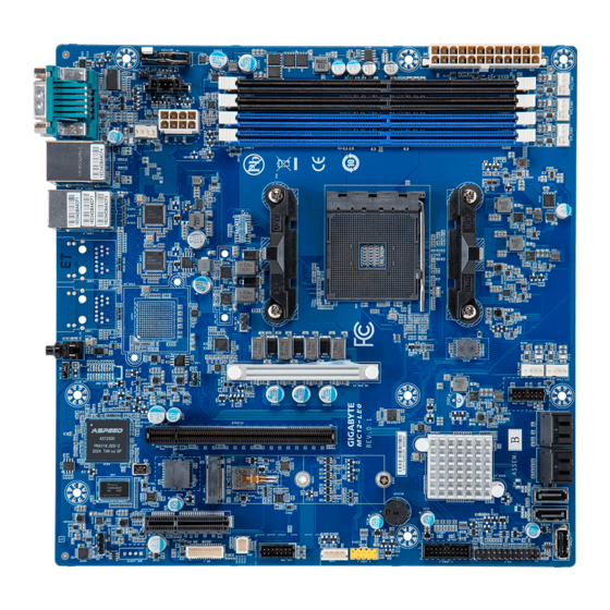
Page 5: Mc12-Le0 Motherboard Layout
MC12-LE0 Motherboard Layout - 5 -... - Page 6 Item Code Description LED_BMC BMC Firmware Readiness LED SW_ID ID Button with LED LAN3_4 GbE LAN Port #3/#4 USB31_MLAN Server Management LAN Port (Top)/USB 3.1 Ports (Bottom) COM_VGA Serial Port (Top)/VGA Port (Bottom) CPU_FAN CPU Fan Connector BATTERY Battery Socket PMBUS PMBus Connector ATX_12V...
-
Page 7: Block Diagram
Block Diagram - 7 -... -
Page 8: Chapter 1 Hardware Installation
Chapter 1 Hardware Installation Installation Precautions The motherboard contains numerous delicate electronic circuits and components which can become damaged as a result of electrostatic discharge (ESD). Prior to installation, carefully read the user's manual and follow these procedures: • Prior to installation, do not remove or break motherboard S/N (Serial Number) sticker or warranty sticker provided by your dealer. -
Page 9: Product Specifications
Product Specifications NOTE: We reserve the right to make any changes to the product specifications and product-related information without prior notice. microATX Š Form Factor 244W x 244D (mm) Š Socket Security AMD Ryzen™ 5000 Series/ 3rd Gen Ryzen™ Processors Š... - Page 10 Š Optional TPM2.0 kit: CTM010 Š Board Aspeed® AST2500 Management Controller Š Socket Security Management GIGABYTE Management Console (AMI MegaRAC SP-X) Web Interface Š Operating Operating temperature: 10°C to 40°C Š Properties Operating humidity: 8-80% (non-condensing) Š Security Non-operating temperature: -40°C to 60°C Š...
-
Page 11: Installing And Removing The Cpu
Installing and Removing the CPU Read the following guidelines before you begin to install the CPU: • Make sure that the motherboard supports the CPU. • Always turn off the computer and unplug the power cord from the power outlet before installing the CPU to prevent hardware damage. -
Page 12: Installing And Removing Memory
Installing and Removing Memory Read the following guidelines before you begin to install the memory: • Make sure that the motherboard supports the memory. It is recommended to use memory of the same capacity, brand, speed, and chips. • Always turn off the computer and unplug the power cord from the power outlet before installing the memory to prevent hardware damage. -
Page 13: Installing And Removing A Memory Module
1-4-2 Installing and Removing a Memory Module Before installing a memory module, make sure to turn off the computer and unplug the power cord from the power outlet to prevent damage to the memory module. Be sure to install DDR4 DIMMs on this motherboard. Follow these instructions to install a DIMM module: Insert the DIMM memory module vertically into the DIMM slot and push it down. -
Page 14: Installing The M.2 Ssd Module
Installing the M.2 SSD Module Follow the steps below to install a M.2 SSD module on your motherboard. Step1. Insert the M.2 SSD module into the slot. Step2. Secure it with the screw, tightening as necessary to fasten the M.2 SSD module in place. Hardware Installation - 14 -... -
Page 15: Back Panel Connectors
Back Panel Connectors Serial Port Connects to serial-based mouse or data processing devices. VGA Port Connect to a monitor device. Server Management LAN Port The LAN port provides Internet connection with data transfer speeds of 10/100/1000Mbps. This port is the dedicated LAN port for Server Management. USB 3.1 Ports The USB port supports the USB 3.1 specification. -
Page 16: Internal Connectors
Internal Connectors BP_1 ATX_12V 12) SPI_TPM SATA_0_1/SATA_2_3/SATA4/SATA5 13) IPMB CPU_FAN 14) LED_BMC SYS_FAN3/4/5 15) BATTERY SYS_FAN1/2 PMBUS F_USB3_1 F_USB2_1 10) FP_1 Read the following guidelines before connecting external devices: • First make sure your devices are compliant with the connectors you wish to connect. •... - Page 17 1/2) ATX/ATX_12V (2x12 Main Power Connector and 2x4 12V Power Connector) With the use of the power connector, the power supply can supply enough stable power to all the components on the motherboard. Before connecting the power connector, first make sure the power supply is turned off and all devices are properly installed. The power connector possesses a foolproof design. Connect the power supply cable to the power connector in the correct orientation.
- Page 18 3) SATA_0_1/SATA_2_3/SATA4/SATA5 (SATA III 6Gb/s Connectors) The SATA connectors conform to SATA III 6Gb/s standard and are compatible with SATA 3Gb/s standard. Each SATA connector supports a single SATA device. Pin No. Definition 4/5/6) CPU_FAN/SYS_FAN1/SYS_FAN2/SYS_FAN3/SYS_FAN4/SYS_FAN5 (Fan Headers) The motherboard has one 4-pin CPU fan header (CPU_FAN), and two 4-pin (SYS_FAN) system fan headers. Most fan headers possess a foolproof insertion design.
- Page 19 7) PMBus Connector The Power Management Bus (PMBus) is a variant of the System Management Bus (SMBus) which is targeted at digital management of power supplies. Pin No. Definition PMBus Clock PMBus Data PMBus Alert 3.3V Sense 8/9) F_USB3_1/F_USB2_1 (Front Panel USB 3.1/2.0 Connector) The header conform to USB 3.1/2.0 specification.
- Page 20 NMI Switch LAN2 Link LED- *Note: Pin 7 & Pin 9 are reserved for Gigabyte systems. The front panel design may differ by chassis. A front panel module mainly consists of power switch, reset switch, power LED, hard drive activity LED, speaker etc. When connecting your chassis front panel module to this header, make sure the wire assignments and the pin assignments are matched correctly.
- Page 21 12) TPM (Trusted Platform Module Connector) Trusted Platform Module (TPM) is an international standard for a secure cryptoprocessor, a dedicated microcontroller designed to secure hardware through integrated cryptographic keys. 13 14 Pin No. Definition Pin No. Definition SPI_PCH_TPM_R_CLK No Connect A_VDD18S5 No Connect LPC_RST_N...
- Page 22 14) LED_BMC (BMC Firmware Readiness LED) State Description BMC firmware is initial Blink BMC firmware is ready AC loss 19) BATTERY (Battery Socket) The battery provides power to keep the values (such as BIOS configurations, date, and time information) in the CMOS when the computer is turned off. Replace the battery when the battery voltage drops to a low level, or the CMOS values may not be accurate or may be lost. •...
-
Page 23: Jumper Settings
Jumper Settings Clear CMOS CLR_CMOS Normal Opera on (Default) Clear CMOS data Hardware Installation - 23 -... -
Page 24: Chapter 2 Bios Setup
Chapter 2 BIOS Setup BIOS (Basic Input and Output System) records hardware parameters of the system in the EFI on the motherboard. Its major functions include conducting the Power-On Self-Test (POST) during system startup, saving system parameters, loading the operating system etc. The BIOS includes a BIOS Setup program that allows the user to modify basic system configuration settings or to activate certain system features. When the power is turned off, the battery on the motherboard supplies the necessary power to the CMOS to keep the configuration values in the CMOS. - Page 25 Main This setup page includes all the items of the standard compatible BIOS. Advanced This setup page includes all the items of AMI BIOS special enhanced features. (ex: Auto detect fan and temperature status, automatically configure hard disk parameters.) Chipset This setup page includes all the submenu options for configuring the functions of the North Bridge. Server Management Server additional features enabled/disabled setup menus. ...
-
Page 26: The Main Menu
The Main Menu Once you enter the BIOS Setup program, the Main Menu (as shown below) appears on the screen. Use arrow keys to move among the items and press <Enter> to accept or enter other sub-menu. Main Menu Help The on-screen description of a highlighted setup option is displayed on the bottom line of the Main Menu. - Page 27 Parameter Description BIOS Information Project Name Displays the project name information. Project Version Displays version number of the BIOS setup utility. Build Date and Time Displays the date and time when the BIOS setup utility was created. BMC Information (Note1) BMC Firmware Version (Note1) Displays BMC firmware version information. Processor Information CPU Brand String/ CPU Speed / Displays the technical specifications for the installed processor(s).
- Page 28 Parameter Description Onboard LAN Information LAN3 MAC Address Displays LAN MAC address information. (Note) LAN4 MAC Address (Note) Displays LAN MAC address information. System Date Sets the date following the weekday-month-day-year format. System Time Sets the system time following the hour-minute-second format. (Note) The number of LAN ports listed will depend on the motherboard / system model.
-
Page 29: Advanced Menu
Advanced Menu The Advanced Menu displays submenu options for configuring the function of various hardware components. Select a submenu item, then press <Enter> to access the related submenu screen. BIOS Setup - 29 -... -
Page 30: Trusted Computing
2-2-1 Trusted Computing Parameter Description TPM20 Device Found Firmware Version Displays the firmware version information. Vendor Displays the vendor information. Enable/Disable BIOS support for security device. OS will not show security device. TCG EFI protocol and INT1A interface will not be Security Device Support available. - Page 31 Parameter Description Schedule an operation for the security device. NOTE: Your computer will reboot during restart in order to change Pending operation the state of a security device. Options available: None, TPM Clear. Default setting is None. Enable/Disable platform hierarchy. Platform Hierarchy Options available: Enabled, Disabled.
-
Page 32: Ast2500 Super Io Configuration
2-2-2 AST2500 Super IO Configuration Description Parameter AST2500 Super IO Configuration Super IO Chip Displays the super IO chip information Serial Port 1 Press [Enter] for configuration of advanced items. Configuration BIOS Setup - 32 -... - Page 33 2-2-2-1 Serial Port 1 Configuration Description Parameter Serial Port 1 Configuration Enable/Disable the Serial Port (COM). When set to Enabled allows you to configure the Serial port 1 settings. When set to Disabled, displays no Serial Port (Note1) configuration for the serial port. Options available: Enabled, Disabled. Default setting is Enabled. Devices Settings Displays the Serial Port 1 device settings. (Note2) Select an optimal settings for Super IO Device.
-
Page 34: S5 Rtc Wake Settings
2-2-3 S5 RTC Wake Settings Parameter Description Enable/Disable system wake on alarm event. Options available: Disabled, Fixed Time. When Fixed Time is selected, Wake System from S5 system will wake on the hr::min::sec specified. Default setting is Disabled. BIOS Setup - 34 -... -
Page 35: Serial Port Console Redirection
2-2-4 Serial Port Console Redirection Parameter Description Select whether to enable console redirection for specified device. Console COM Console redirection enables the users to manage the system from a remote Redirection (Note)) location. Options available: Enabled, Disabled. Default setting is Disabled. Press [Enter] to configure advanced items. Please note that this item is configurable when COM Console Redi- rection is set to Enabled. - Page 36 Parameter Description Parity Š – A parity bit can be sent with the data bits to detect some transmission errors. – Even: parity bit is 0 if the num of 1's in the data bits is even. – Odd: parity bit is 0 if num of 1's in the data bits is odd. –...
- Page 37 Parameter Description Legacy Console Redirection Press [Enter] to configure advanced items. Redirection COM Port Š – Selects a COM port for Legacy serial redirection. – Default setting is COM1. Resolution Š – Selects the number of rows and columns used in Console Redirection for legacy OS support. Legacy Console Redirection –...
- Page 38 Parameter Description Flow Control EMS Š – Flow control can prevent data loss from buffer overflow. When sending data, if the receiving buffers are full, a 'stop' signal can Serial Port for Out-of-Band be sent to stop the data flow. Once the buffers are empty, a 'start' EMS Console Redirection signal can be sent to re-start the flow. Hardware flow control uses Settings(continued) two wires to send start/stop signals. – Options available: None, Hardware RTS/CTS, Software Xon/Xoff. Default setting is None.
-
Page 39: Cpu Configuration
2-2-5 CPU Configuration Description Parameter CPU Configuration Displays the module version information. Module Version Displays the AGESA version information. AGESA Version Enable/Disable the generation of ACPI_PPC, _PSS, and _PCT objects. PSS Support Options available: Enabled, Disabled. Default setting is Enabled. Options available: PState 0, PState 1, PState 2. Default setting is PState 0. PPC Adjustment Enable/Disable No-execute page protection Function. -
Page 40: Sata Configuration
2-2-6 SATA Configuration Parameter Description Displays the installed HDD devices information. System will automatically SATA Configuration detect HDD type. BIOS Setup - 40 -... -
Page 41: Pci Subsystem Settings
2-2-7 PCI Subsystem Settings Description Parameter Change the PCIEx4 lanes. PCIEx4 Slot Options available: Disabled, Enabled. Default setting is Enabled. When enabled, this setting will initialize the device expansion ROM for the related PCI-E slot. PCIEx4 I/O ROM Options available: Disabled, x16, x8 x8, x8 x4 x4, x4 x4 x8, x4 x4 x4 x4. Default setting is x16. - Page 42 Description Parameter If the system has SR-IOV capable PCIe devices, this item Enable/Disable Single Root IO Virtualization Support. SR-IOV Support Options available: Enabled, Disabled. Default setting is Disabled. BIOS Setup - 42 -...
-
Page 43: Usb Configuration
2-2-8 USB Configuration Parameter Description USB Configuration USB Module Version Displays the USB module version information. USB Controllers Displays the supported USB controllers. USB Devices: Displays the USB devices connected to the system. Enable/Disable the Legacy USB support function. AUTO option disables legacy support if no USB devices are connected. - Page 44 Parameter Description Enables the I/O port 60h/64h emulation support. This should be enabled for the complete USB Keyboard Legacy support for non- Port 60/64 Emulation USB aware OS. Options available: Enabled, Disabled. Default setting is Enabled. USB hardware delays and time-outs Selects the time-out value for USB Control/Bulk/Interrupt transfers.
-
Page 45: Network Stack Configuration
2-2-9 Network Stack Configuration Parameter Description Enable/Disable the UEFI network stack. Network Stack Options available: Enabled, Disabled. Default setting is Enabled. Enable/Disable the Ipv4 PXE feature. Ipv4 PXE Support (Note) Options available: Enabled, Disabled. Default setting is Enabled. Enable/Disable the Ipv4 HTTP feature. Ipv4 HTTP Support (Note) Options available: Enabled, Disabled. -
Page 46: Nvme Configuration
2-2-10 NVMe Configuration Parameter Description NVMe Configuration Displays the NVMe devices connected to the system. BIOS Setup - 46 -... -
Page 47: Tls Auth Configuration
2-2-11 Tls Auth Configuration Parameter Description Press [Enter] for configuration of advanced items. Enroll Cert Š – Press [Enter] to enroll a certificate • Enroll Cert Using File • Cert GUID Server CA Configuration Input digit character in 1111111-2222-3333-4444-1234567890ab format. – Commit Changes and Exit – Discard Changes and Exit Delete Cert Š Press [Enter] for configuration of advanced items. Client Cert Configuration BIOS Setup - 47 -... -
Page 48: Amd Cbs
2-2-12 AMD CBS Parameter Description AMD CBS CPU Common Options Press [Enter] for configuration of advanced items. DF Common Options Press [Enter] for configuration of advanced items. UMC Common Options Press [Enter] for configuration of advanced items. NBIO Common Options Press [Enter] for configuration of advanced items. FCH Common Options Press [Enter] for configuration of advanced items. Chipset Common Options Press [Enter] for configuration of advanced items. Soc Miscellaneous Control Press [Enter] for configuration of advanced items. BIOS Setup - 48 -... - Page 49 2-2-12-1 CPU Common Options Parameter Description CPU Common Options Press [Enter] for configuration of advanced items. Custom Core Pstates Š Performance – Allows you to accept or decline enabling Custom Core Pstates. When accepted, you can disable or customize core pstates. Press [Enter] for configuration of advanced items. L1 Stream HW Prefetcher Š...
- Page 50 Parameter Description Enable/Disable the Core Performance Boost function. Core Performance Boost Options available: Auto, Disabled. Default setting is Auto. Controls the IO based C-state generation and DF C-states. Global C-State Control Options available: Auto, Enabled, Disabled. Default setting is Auto. Configures the Power Supply Idle Control.
- Page 51 2-2-12-2 DF Common Options Parameter Description DF Common Options Press [Enter] for configuration of advanced items. DRAM scrub time Š – Provide a value that is the number of hours to scrub memory. – Options available: Auto, Disabled, 1 hour, 4 hours, 8 hours, 16 hours, 24 hours, 48 hours. Default setting is Auto. Poison scrubber control Š...
- Page 52 Parameter Description Memory interleaving size Š – Controls the memory interleaving size. This determines the starting address of the interleave (bit 8, 9, 10 or 11). – Options available: Auto, 256Bytes, 512Bytes, 1KB, 2KB. Default setting is Auto. 1TB remap Š...
- Page 53 Parameter Description xGMI TXEQ Mode Š – Configures xGMI TXEQ/RX vetting Mode. Link – Options available: Auto, TXEQ_Disabled, TXEQ_Lane, TXEQ_Link, (continued) TXEQ_RX_Vet. Default setting is Auto. PcsCG control Š – Options available: Auto, Enable. Default setting is Auto. Disable DF to external Enable/Disable SyncFlood to UMC & downstream slaves. downstream IP Options available: Auto, Sync flood disabled, Sync flood enabled.
- Page 54 2-2-12-3 UMC Common Options Parameter Description UMC Common Options DDR4 Common Options Press [Enter] for configuration of advanced items. DRAM Memory Mapping Press [Enter] for configuration of advanced items. NVDIMM Press [Enter] for configuration of advanced items. Memory MBIST Press [Enter] for configuration of advanced items. BIOS Setup - 54 -...
- Page 55 2-2-12-3-1 DDR4 Common Options Parameter Description DDR4 Common Options Press [Enter] to enable / disable restrictions for DDR4 frequency and voltage programming. Memory speeds will be capped at AMD guidelines. Decline Š Enforce POR Accept Š – Overclock: Enable/Disable Memory Overclock Settings. –...
- Page 56 Parameter Description Press [Enter] for configuration of advanced items. CAD Bus Timing User Controls Š – Setup time on CAD bus signals to Auto or Manual. CAD Bus Configuration – Options available: Auto, Manual. Default setting is Auto. CAD Bus Drive Strength User Controls Š – Drive Strength on CAD bus signals to Auto or Manual. –...
- Page 57 Parameter Description ECC Configuration Š – DRAM ECC Symbol Size » Configures the DRAM ECC Symbol Size. » Options available: Auto, x4, x8, x16. Default setting is Auto. – DRAM ECC Enable » Enable/Disable DRAM ECC. When set to Auto, it will set ECC to Common RAS enable.
- Page 58 2-2-12-3-2 DRAM Memory Mapping Parameter Description DRAM Memory Mapping Interleave memory blocks across the DRAM chip selects for node 0. Chipselect Interleaving Options available: Auto, Disabled. Default setting is Auto. Configures the BankGroupSwap. BankGroupSwap (BGS) is a new memory mapping option in AGESA that alters how applications get assigned to BankGroupSwap physical locations within the memory modules.
- Page 59 2-2-12-3-3 NVDIMM Parameter Description NVDIMM Displays the information of the devices/controllers if installed BIOS Setup - 59 -...
- Page 60 2-2-12-3-4 Memory MBIST Parameter Description Memory MBIST Enable/Disable the Memory MBIST function. MBIST Enable Options available: Enabled, Disabled. Default setting is Enabled. Selects MBIST Test Mode. Interface Mode: Tests Single and Multiple CS transactions and Basic Connectivity. MBIST Test Mode (Note) Data Eye Mode: Measures Voltage vs.
- Page 61 Parameter Description Aggressor Channel Š – This item helps read the aggressors channels. – Options available: Disabled, 1 Aggressor Channel, 3 Aggressor Channels, 7 Aggressor Channels. Default setting is 1 Aggressor Channel. Aggressor Static Lane Control Š – Enable/Disable the Aggressor Static Lane Control function. –...
- Page 62 2-2-12-4 NBIO Common Options Parameter Description NBIO Common Options Enable/Disable the IOMMU function. IOMMU Options available: Auto, Enabled, Disabled. Default setting is Auto. Press [Enter] to configure advanced items. Declined Š Accepted Š – Precision Boost Overdrive » Options available: Auto, Enable, Disable, Manual. Default setting is Auto.
- Page 63 Parameter Description VDDG Voltage Control Š – Options available: Auto, Manual. Default setting is Auto. SoC/Uncore OC Mode Š – Forces CPU SoC/Uncore components (e.g. Infinity Fabric, memory, and integrated graphics) to run at their maximum specified frequency XFR Enhancement at all times. May improve performance at the expense of idle power (continued) savings.
- Page 64 Parameter Description CPPC Š – Options available: Auto, Enabled, Disabled. Default setting is Auto. CPPC Preferred Cores Š SMU Common Options – Options available: Auto, Enabled, Disabled. Default setting is Auto. (continued) NBIO LCLK DPM Š – This setting controls how the NBIO Power Management is controlled. –...
- Page 65 2-2-12-5 FCH Common Options Parameter Description FCH Common Options Press [Enter] for configuration of advanced items. SATA Enable Š – Enable/Disable OnChip SATA controller. – Options available: Auto, Enabled, Disabled. Default setting is Auto. SATA Mode Š – Selects OnChip SATA Type. – Options available: AHCI, AHCI as ID 0x7904, Auto, RAID. Default SATA Configuration Options setting is AHCI.
- Page 66 2-2-12-6 Chipset Common Options Parameter Description Chipset Common Options Press [Enter] for configuration of advanced items. SATA Mode Š – Select SATA Type. SATA Configuration Options – Options available: AHCI, RAID, Auto. Default setting is Auto. Aggressive SATA Device Sleep Port 0/1 Š – Options available: Auto, Enable, Disable. Default setting is Auto. BIOS Setup - 66 -...
- Page 67 2-2-12-7 SOC Miscellaneous Control Parameter Description SOC Miscellaneous Control Enable/Disable the ConsoleOut function for ABL. ABL Console Out Control Options available: Auto, Enable, Disable. Default setting is Auto. ABL Basic Console Out Enable/Disable the Basic ConsoleOut function for ABL. Options available: Auto, Enable, Disable. Default setting is Auto. Control (Note) To Control the total number of PMU debug messages.
-
Page 68: Iscsi Configuration
2-2-13 iSCSI Configuration Parameter Description Press [Enter] and name iSCSI Initiator. Only IQN format is accepted. iSCSI Initiator Name Range: from 4 to 223 Add an Attempt Press [Enter] to configure advanced items. Delete Attempts Press [Enter] to configure advanced items. Change Attempt Order Press [Enter] to configure advanced items. BIOS Setup - 68 -... -
Page 69: Intel(R) I210 Gigabit Network Connection
2-2-14 Intel(R) I210 Gigabit Network Connection Parameter Description Link Speed Š – Allows for automatic link speed adjustment. – Options available: Auto Negotiated, 10 Mbps Half, 10 Mbps Full, 100 Mbps Half, 100 Mbps Full. Default setting is Auto Negotiated. Wake On LAN Š NIC Configuration –... - Page 70 Parameter Description Specifies the link status of the port. Link Status Displays the MAC address of the Ethernet controller. MAC Address Displays the virtual MAC address of the Ethernet controller. Virtual MAC Address BIOS Setup - 70 -...
-
Page 71: Vlan Configuration
2-2-15 VLAN Configuration Parameter Description Press [Enter] to configure advanced items. Create new VLAN Š VLAN ID Š – Sets VLAN ID for a new VLAN or an existing VLAN. – Press the <+> / <-> keys to increase or decrease the desired values. – The valid range is from 0 to 4094. Priority Š... -
Page 72: Mac Ipv4 Network Configuration
2-2-16 MAC IPv4 Network Configuration Parameter Description Indicates whether network address is configured successfully or not. Configured Options available: Enabled, Disabled. Default setting is Disabled. Options available: Enabled, Disabled. Default setting is Enabled. Enable DHCP (Note) Local IP Address Press [Enter] to configure local IP address. (Note) Press [Enter] to configure local NetMask. Local NetMask (Note) Press [Enter] to configure local Gateway Local Gateway (Note) Press [Enter] to configure local DNS servers Local DNS Servers... -
Page 73: Mac Ipv6 Network Configuration
2-2-17 MAC IPv6 Network Configuration Parameter Description Press [Enter] to configure advanced items. Displays the MAC Address information. Š Interface ID Š – The 64 bit alternative interface ID for the device. The string is colon separated. e.g. ff:dd:88:66:cc:1:2:3. DAD Transmit Count Š – The number of consecutive Neighbor solicitation messages sent Enter Configuration Menu while performing Duplicate Address Detection on a tentative address. -
Page 74: Chipset Setup Menu
Chipset Setup Menu Chipset Setup menu displays submenu options for configuring the function of the South Bridge and North Bridge. Select a submenu item, then press <Enter> to access the related submenu screen. Parameter Description Select SATA Type. SATA Mode Options available: AHCI, RAID. -
Page 75: North Bridge
2-3-1 North Bridge Parameter Description North Bridge Configuration Selects Above 4GB MMIO Limit to 38~43 bits limit. This option works only when "Above 4G decoding" is enabled. Above 4GB MMIO Limit Options available: 40bit (1TB), 41bit (2TB), 42bit (4TB), 43bit (8TB). Default setting is 40bit (1TB). Memory Information Total Memory Displays the total memory information. -
Page 76: Server Management Menu
Server Management Menu Parameter Description Enable/Disable FRB-2 timer (POST timer). FRB-2 Timer Options available: Enabled, Disabled. Default setting is Enabled. Configures the FRB2 Timer timeout. FRB-2 Timer (Note1) Options available: 3 minutes, 4 minutes, 5 minutes, 6 minutes. Default setting is 6 timeout minutes. FRB-2 Timer Configures the FRB2 Timer policy. - Page 77 Parameter Description Bmc self test log Press [Enter] to configure advanced items. View FRU Press [Enter] to view the FRU information. Information BMC VLAN Press [Enter] to configure advanced items. Configuration BMC network Press [Enter] to configure advanced items. configuration IPv6 BMC Network Press [Enter] to configure advanced items. Configuration BIOS Setup - 77 -...
-
Page 78: System Event Log
2-4-1 System Event Log Parameter Description Enabling / Disabling Options Change this item to enable or disable all features of System Event SEL Components Logging during boot. Options available: Enabled, Disabled. Default setting is Enabled. Erasing Settings Choose options for erasing SEL. Erase SEL Options available: No/Yes, On next reset/Yes, On every reset. -
Page 79: Bmc Self Test Log
2-4-2 Bmc self test log Parameter Description Log area usage = 00 out of 20 logs Choose options for erasing SEL. Erase Log Options available: Yes, On every reset/ No. Default setting is Yes, On every reset. Choose options for reactions to a full SEL. When log is Full Options available: Clear Log, Do not log any more. -
Page 80: View Fru Information
2-4-3 View FRU Information The FRU page is a simple display page for basic system ID information, as well as System product information. Items on this window are non-configurable. (Note) The model name will vary depends on the product you purchased BIOS Setup - 80 -... -
Page 81: Bmc Vlan Configuration
2-4-4 BMC VLAN Configuration Parameter Description BMC VLAN Configuration Sets VLAN ID for a new VLAN or an existing VLAN. BMC VLAN ID Press the <+> / <-> keys to increase or decrease the desired values. The valid range is from 0 to 4094. Sets 802.1Q Priority for a new VLAN or an existing VLAN. -
Page 82: Bmc Network Configuration
2-4-5 BMC Network Configuration Parameter Description BMC network configuration Lan Channel 1 Selects to configure LAN channel parameters statically or dynamically (DHCP). Do nothing option will not modify any BMC network parameters Configuration Address source during BIOS phase. Options available: Unspecified, Static, DynamicBmcDhcp. Default setting is Static. Station IP address Displays IP Address information. Displays Subnet Mask information. Subnet mask Please note that the IP address must be in three digitals, for example, 192.168.000.001. -
Page 83: Ipv6 Bmc Network Configuration
2-4-6 IPv6 BMC Network Configuration Parameter Description IPv6 BMC network configuration IPv6 BMC Lan Channel 1 Enable/Disable IPv6 BMC LAN channel function. When this item is disabled, the system will not modify any BMC network during BIOS IPv6 BMC Lan Option phase. Options available: Unspecified, Disable, Enable. Default setting is Enable. -
Page 84: Security Menu
Security Menu The Security menu allows you to safeguard and protect the system from unauthorized use by setting up access passwords. There are two types of passwords that you can set: • Administrator Password Entering this password will allow the user to access and change all settings in the Setup Utility. •... -
Page 85: Secure Boot
2-5-1 Secure Boot The Secure Boot submenu is applicable when your device is installed the Windows 8 (or above) operating ® system. Parameter Description System Mode Displays if the system is in User mode or Setup mode. Enable/ Disable the Secure Boot function. Secure Boot Options available: Enabled, Disabled. - Page 86 Parameter Description Press [Enter] to configure advanced items. Please note that this item is configurable when Secure Boot Mode is set to Custom. Factory Key Provision Š – Allows to provision factory default Secure Boot keys when system is in Setup Mode. – Options available: Enabled, Disabled. Default setting is Disabled. Restore Factory Keys Š...
-
Page 87: Boot Menu
Boot Menu The Boot menu allows you to set the drive priority during system boot-up. BIOS setup will display an error message if the legacy drive(s) specified is not bootable. Parameter Description Boot Configuration Enable/Disable showing the logo during POST. Full Screen LOGO Show Options available: Enabled, Disabled. Default setting is Enabled. Selects the boot mode. -
Page 88: Save & Exit Menu
Save & Exit Menu The Save & Exit menu displays the various options to quit from the BIOS setup. Highlight any of the exit options then press <Enter>. Parameter Description Save Options Saves changes made and closes the BIOS setup. Save Changes and Exit Options available: Yes, No. -
Page 89: Bios Post Beep Code (Ami Standard)
BIOS POST Beep code (AMI standard) 2-8-1 PEI Beep Codes # of Beeps Description Memory not Installed. Memory was installed twice (InstallPeiMemory routine in PEI Core called twice) Recovery started DXEIPL was not found DXE Core Firmware Volume was not found Recovery failed S3 Resume failed Reset PPI is not available...