Table of Contents
Advertisement
Quick Links
SAFETY PRECAUTION FOR SERVICE MANUAL .......................................................................................................... 2
PRECAUTIONS FOR USING LEAD-FREE SOLDER ...................................................................................................... 3
SPECIFICATIONS ............................................................................................................................................................ 4
NAMES OF PARTS .......................................................................................................................................................... 5
DISASSEMBLY ................................................................................................................................................................. 7
REMOVING AND REINSTALLING THE MAIN PARTS .................................................................................................... 9
ADJUSTMENT ................................................................................................................................................................ 10
BLOCK DIAGRAM .......................................................................................................................................................... 31
WIRING SIDE OF P.W.BOARD / SCHEMATIC DIAGRAM ............................................................................................ 33
VOLTAGE ....................................................................................................................................................................... 47
NOTES ON SCHEMATIC DIAGRAM ............................................................................................................................. 48
TYPES OF TRANSISTOR AND DIODE ......................................................................................................................... 48
WAVEFORMS OF MD CIRCUIT .................................................................................................................................... 49
TROUBLESHOOTING .................................................................................................................................................... 51
FUNCTION TABLE OF IC ............................................................................................................................................... 54
PARTS GUIDE/EXPLODED VIEW
SERVICE MANUAL
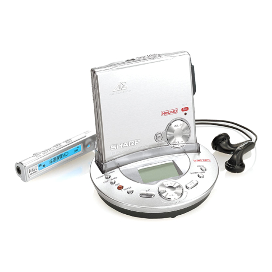
1-BIT PORTABLE MINIDISC RECORDER
MODEL
CONTENTS
SHARP CORPORATION
IM-DR580H(S)
IM-DR580H(BK)
• In the interests of user-safety the set should be restored to its
original condition and only parts identical to those specified be
used.
This document has been published to be used
for after sales service only.
The contents are subject to change without notice.
IM-DR580H
No. SY380IMDR580H
Page
Advertisement
Table of Contents

Related Manuals for Sharp IM-DR580H(S)


Summary of Contents for Sharp IM-DR580H(S)
-
Page 1: Table Of Contents
TROUBLESHOOTING ..............................51 FUNCTION TABLE OF IC ............................... 54 PARTS GUIDE/EXPLODED VIEW PACKING METHOD (FOR U.K. ONLY) This document has been published to be used SHARP CORPORATION for after sales service only. The contents are subject to change without notice. -
Page 2: Safety Precaution For Service Manual
IM-DR580H SAFETY PRECAUTION FOR SERVICE MANUAL Precaution to be taken when replacing and servicing the Laser Pickup. The AEL (Accessible Emission Level) of Laser Power Output for this model is specified to be lower than Class 1 Requirements. However, the following precautions must be observed during servicing to protect your eyes against exposure to the laser beam. (1) When the cabinet has been removed, the power is turned on without a compact disc, and the Pickup is on a position outer than the lead-in position, the Laser will light for several seconds to detect a disc. -
Page 3: Precautions For Using Lead-Free Solder
IM-DR580H PRECAUTIONS FOR USING LEAD-FREE SOLDER 1. Employing lead-free solder "All PWBs" of this model employs lead-free solder. The LF symbol indicates lead-free solder, and is attached on the PWBs and service manuals. The alphabetical character following LF shows the type of lead-free solder. Example: Indicates lead-free solder of tin, silver and copper. -
Page 4: Specifications
IM-DR580H FOR A COMPLETE DESCRIPTION OF THE OPERATION OF THIS UNIT, PLEASE REFER TO THE OPERATION MANUAL. SPECIFICATIONS Power source: DC 1.2 V: Rechargeable Nickel-Metal Hydride Battery (AD-N55BT) x 1 DC 1.5 V: Commercially available, "AA" size (LR6), alkaline battery x 1 DC 3 V: AC adaptor (AC 110 - 240 V, 50/60 Hz), with the multi-link station Power consumption:... -
Page 5: Names Of Parts
IM-DR580H NAMES OF PARTS Main unit 1. Stop/Power Off/Hold Button 2. Record Indicator 3. Play/Fast Forward/Fast Reverse/ Volume Button 4. Battery Connection Terminals 5. Multi-link Station Connection Terminal 6. Microphone Input Socket 7. Remote Control/ Earphone Output Socket 8. Open Lever 9. - Page 6 IM-DR580H Multi-link station 1. Playback/Recording Mode Switching/ Charge Button 2. Display/Bass Button 3. Record Button 4. Erase Button 5. Power On or Off/Stop Button 6. Fast Forward/Fast Reverse/ Recording Level/Volume Button 7. Play/Pause Button 8. Enter/USB Switching Button 9. Menu Button 10.
-
Page 7: Disassembly
IM-DR580H DISASSEMBLY (A1)x2 Cares before disassembling ø1.4x1.5mm When assembling the machine after disassembling or Top Cabinet repair, observe the following requirements so as to ensure safety and performance. 1. Remove the batteries from the machine, and take out the (A1)x1 ø1.4x1.5mm mini-disc. - Page 8 IM-DR580H Multi-Link Station PROCEDURE FIGURE STEP REMOVAL Bottom Cabinet 1. Screw ..... (A1) x4 Multi-Link Station 1. Hook ....... (B1) x3 B PWB 2. Flat Cable ....(B2) x1 3. Hook ....... (B3) x2 4. Multi-Link Station B PWB Holder ..... (B4) x1 Multi-Link Station 1.
-
Page 9: Removing And Reinstalling The Main Parts
IM-DR580H REMOVING AND REINSTALLING THE MAIN PARTS Remove the MD mechanism according to the disassembling (A2)x3 methods 1 to 4. (See Page 7.) ø1.4x1.8mm How to remove the spindle motor (See Fig. 9-1.) Spindle Motor 1. Remove the solder joints (A1) x 4 of flexible PWB. 2. -
Page 10: Adjustment
IM-DR580H ADJUSTMENT Test disc MD adjustment needs two types of disc, namely recording disc (low reflection disc) and playback-only disc (high reflection disc). Type Test disc Parts No. High reflection disc MMD-110 (TEAC Test MD) 88GMMD-110 Low reflection disc MMD-213A (TEAC Test MD) 88GMMD-213A Low reflection disc Recording mini disc... - Page 11 IM-DR580H To enter each mode from the test mode STOP "TEST" Press the MENU button (on the remote control or multi-link station). Select each mode using the SKIP UP/DOWN button. Test Mode 1. AUTO 1 Mode • Perform preliminary automatic adjustment. 6.
- Page 12 IM-DR580H 4. T-REC Mode 7. E_DATA display Mode • When the STOP button is pressed while the REC menu appears, or • Reversing when REVERSE button is pressed. in the REC mode or continuous record mode, the mode changes to •...
- Page 13 IM-DR580H Explanation of error history code Error messages 13 h : Adjustment servo retraction excessive retrial Can't READ (*) Focus pulled 16 h : C. IN detection time-over Servo adjustment 17 h : A, B, E, F, and TCRSO offset measurement value out of Track search tolerable range TOC information reading...
- Page 14 IM-DR580H EEPROM DATA LIST (EEPROM version : d) Focus setting Spindle setting Item display Item display Set values Set values S P G _ F G 1 _ S P 1 _ F G 2 _ P G 2 _ F G 3 _ R G 2 _ F F 0 _...
- Page 15 IM-DR580H Tracking setting Sled setting Item display Item display Set values Set values T G 1 _ S K S _ T G 2 _ S K L _ T G 3 _ S L C _ T F 0 _ S T L _ T F 1 _ S T M _...
- Page 16 IM-DR580H Control setting Item display Item display Set values Set values C T 0 _ R 4 1 _ C T 1 _ G U P _ C T 2 _ S C G _ C T 3 _ K 1 0 _ U S A _ K 1 1 _ R C E _...
- Page 17 IM-DR580H ROM Correction setting Item display Set values Item display Set values R M 3 3 R M 0 0 R M 3 4 R M 0 1 R M 3 5 R M 0 2 R M 3 6 R M 0 3 R M 3 7 R M 0 4...
- Page 18 IM-DR580H Do the following when replacing the mechanism, the pickup, the EEPROM (IC402), the LSI (IC201) or the main PWB unit. Enter the test mode, move the pickup to the most internal periphery and execute AUTO1. (Use the disc of MMD-213A.) A U T O 1 PLAY (During the spare style automatic adjustment.)
- Page 19 IM-DR580H Test Mode Start · Completion method • Starting method of the test mode (1) When using the main unit and remote control When the following operation is performed using the remote control while the product is in the stand-by state (the display is off), the test mode starts. Switch the "HOLD"...
- Page 20 IM-DR580H Change of Test Mode Menus MENU T E S T : Test mode stop SKIP UP SKIP DOWN Slide external Slide internal periphery move periphery move SKIP DOWN A U T O 1 : Pre-automatic adjustment menu SKIP UP SKIP DOWN A U T O J SKIP UP...
- Page 21 IM-DR580H Servo Pre-automatic Adjustment A U T O 1 : Pre-automatic adjustment menu Adjustment error PLAY A T 1 : During pre-automatic adjustment Adjustment error A D J . N G Normal end : Pre-adjustment error (adjustment value output) A D J . O K : Pre-adjustment normal end (adjustment value output) PLAY A T 2...
- Page 22 IM-DR580H Continuous Playback • Continuous playback from current pickup position : Continuous playback menu P L A Y PLAY E r A D J AUTO1 Practice finish ? AUTO2 Practice finish ? AUTO2 Practice No error ? A D J. N G SQ : Continuous playback (pit section) S Q # # # # AP : Continuous playback (groove section)
- Page 23 IM-DR580H Continuous Record Enter the EEPROM setting mode, and press the SKIP UP button. Change the MSL setting value from 00 to 08 by using CTRL_ (control setting menu). (If the MSL remains in 00, no signal is recorded.) • Continuous record from the current pickup position : Continuous record menu R E C PLAY...
- Page 24 IM-DR580H Servo Pre-Manual Adjustment M A N U 1 : Pre-Manual Adjustment menu PLAY : Temperature code indication T M P : Temperature code SKIP UP SKIP DOWN : A signal offset (AINO) measurement : Measurement value SKIP UP SKIP DOWN : B signal offset (BINO) measurement : Measurement value SKIP UP...
- Page 25 IM-DR580H * In the specific setting display state the setting change digit changes when the [REC] button is pressed. • In the case of the setup value two digits. 1st digit (initial value) 2nd digit • In the case of the setup value three digits. 1st digit (initial value) 2nd digit 3nd digit...
- Page 26 IM-DR580H Servo ATT Manual Adjustment M A N U 2 : ATT manual adjustment menu PLAY : Temperature code indication T M P : Temperature code SKIP UP SKIP DOWN : Laser ON (play power) L O N SKIP UP SKIP DOWN : Pit section E-ATT (tracking) setting : ATT setting...
- Page 27 IM-DR580H * If the [DISP] button is pressed, the display changes as follows. • LPFABO measurement value : Low-reflection pit section A-ATT (focus) setting : Low-reflection pit section B-ATT (focus) setting : Low-reflection groove section A-ATT (focus) setting : Low-reflection groove section B-ATT (focus) setting DISP DISP : LPFABO measurement value indication...
- Page 28 IM-DR580H Servo Pre-adjustment Value Check R S L T 1 : Pre-adjustment Value Check menu PLAY : A signal offset measurement value (setting) SKIP UP SKIP DOWN : B signal offset measurement value (setting) SKIP UP SKIP DOWN : E signal offset measurement value (setting) SKIP UP SKIP DOWN : F signal offset measurement value (setting)
- Page 29 IM-DR580H ATT Setting Check R S L T 2 : ATT Setting Check menu PLAY : Pit section E-ATT (tracking) setting SKIP UP SKIP DOWN : Pit section F-ATT (tracking) setting SKIP UP SKIP DOWN : Groove section E-ATT (tracking) setting SKIP UP SKIP DOWN : Groove section F-ATT (tracking) setting...
- Page 30 IM-DR580H From the front SKIP UP SKIP DOWN : Error history 6 indication E 6 $ $ $ $ : Error code SKIP UP SKIP DOWN : Error history 7 indication E 7 $ $ $ $ : Error code SKIP UP SKIP DOWN : Error history 8 indication...
-
Page 31: Block Diagram
IM-DR580H FROM MULTI-LINK FROM MULTI-LINK STATION PWB STATION PWB FROM MULTI-LINK STATION PWB J702 J703 REMOTE CONTROL/ MIC IN HEADPHONES Figure 31 BLOCK DIAGRAM (1/2) – 31 –... - Page 32 IM-DR580H 2.6V LCD DATA OPTICAL IN JA01 OPTICAL/ LINE IN LINE IN JA02 AUDIO OUT AUDIO OUTPUT USB IN JA03 USB 5V JA05 SWA11 SPEAKER OUTPUT SWA01~SWA10 SWA15,SWA16 DC IN 3V JA04 DC IN DC GND D GND Figure 32 BLOCK DIAGRAM (2/2) –...
-
Page 33: Wiring Side Of P.w.board / Schematic Diagram
IM-DR580H P35 9 - F TO MAIN PWB CN101 OPTICAL PICKUP (17) M903 LCD UNIT LIFT MOTOR (114) CNA101 P36 5 - B M901 TO MULTI-LINK SPINDLE MOTOR STATION A PWB VOLUME MECHANISM FLEXIBLE PWB (15) SKIP UP STOP SKIP DOWN VOLUME DOWN... - Page 34 IM-DR580H MAIN PWB-A (TOP VIEW) J703 J702 REMOTE CONTROL/HEADPHONES MIC IN SW402 OPEN TP711 SW901 TP406 PROTECT TP302 Q721 TP721 D862 TP723 TP407 L752 Q863 L762 TPC15 C772 TP701 C784 C250 C451 L862 TP301 R700 TPC12 C841 C861 D841 C801A Q841 BATTERY TERMINAL,- Q802...
- Page 35 IM-DR580H : Through-hole where the top, bottom and +B patterns are connected. : Through-hole where the top, bottom and ground patterns are connected. : Through-hole where the top and bottom patterns are connected. MAIN PWB-A (BOTTOM VIEW) C705 L714 IC303 SW401 EJECT R332...
- Page 36 IM-DR580H Lead-free solder indication Lead-free solder is used in this main PWB. Refer to “Precautions for handling lead-free solder” for instructions and precautions. MULTI-LINK STATION A FROM LCD UNIT P33 1 - D PWB-B1 (TOP VIEW) SWA09 SWA08 SKIP TPA12 VOLUME DOWN DOWN...
- Page 37 IM-DR580H MULTI-LINK STATION A PWB-B1 (BOTTOM VIEW) LA21 LA22 LA12 CA24 CA45 LA103 MULTI-LINK STATION B PWB-B2 (BOTTOM VIEW) Figure 37 WIRING SIDE OF P.W.BOARD (5/5) – 37 –...
- Page 38 IM-DR580H MAIN PWB-A MAIN PWB-A PLAYBACK SIGNAL RECORD SIGNAL C111 C109 C108 CK139 48 47 46 45 44 43 42 41 40 39 38 1234 BIAS EFMAGC EFMO C131 SYCPW CK111 ADAGI CK112 C132 0.22 CK113 DIFF ADAGC CK114 ADIPNF C102 REFI ADIPO...
- Page 39 IM-DR580H OPERATION BUTTON FLEXIBLE PWB VOL- HAKEY TP451 TP451 PLAY TP452 R451 TP452 TP453 TP453 TP454 TP454 TP455 R452 TP455 TP456 TP456 TP457 TP457 VOL+ HKINT TP458 TP458 R453 2.2K SKIP DOWN LED_R STOP R457 PCNT1 IC203 C208 74LVX74T ROUT ROUTX D-FLIP FLOP LOUTX...
- Page 40 IM-DR580H MAIN PWB-A OPIC VCC_MAIN OPTICAL PICKUP TP352 EFMOX EFMO DCNT2 DCNT1 C357 IC351 HDON 74ACT08T HEAD DRIVER R351 VCC_HEAD C353 C602 5 4 3 6 5 4 1 2 3 C601 C603 R603 R604 C604 D351 1 2 3 SBE803 C652 HDIHS...
- Page 41 IM-DR580H 5 6 7 8 R412 R411 TP411A 100K VCC_MAIN BTRON VCC4_5 R416 96 95 94 93 92 91 90 89 88 87 86 85 84 83 82 81 80 79 SYPVUP R422 _FOK 100K SYRS JPNP SYRD MCPGIN _SYRD _MCPGI SYWR LDCNT1...
- Page 42 IM-DR580H MAIN PWB-A C509 MCPGIN C510 TP501 8 7 6 5 4 3 2 1 C701 PCNT1 NOISE IC771 IC501 6219B24M AK5354VT IC701 AD CONVERTER NJM2173AP R701 MIC AMP. 330K DSPSTB 9 10 11 12 13 14 15 16 2.4V REGULATOR STBY DSPSCK MCNT...
- Page 43 IM-DR580H R727 220K L714 100mA TP714 L713 L-ch TP713 L712 R-ch TP712 C731 C724 TP711 0.001 J702 MIC IN L711 100 MHz C715 TPC01 DSPSTB TPC02 DSPSCK TPC03 DSPDAT TPC04 CAKEY TPC05 CIKEY TPC06 R717 TPC07 TPC08 TPC09 TPC10 TPC11 C738 R443 TPC12...
- Page 44 IM-DR580H MAIN PWB-A DSP_IF0 USBVSS CPU_CK DSPIF0 DSP_IF1 DSPIF1 USB_EN DSP_IF2 DSPIF2 IC301 VDC0 USBVDD CXD1875T VSC0 USB_SW SECURITY PLLVSS DSP_IF3 DSPIF3 BTRON PLLVDD EXT_IF0 PLLTHRU VCC4_5 VDEA0 EXT_IF1 VSC2 EXT_IF2 TEST1 13 14 15 16 17 18 19 20 21 22 23 24 C332 Q333 TP302...
- Page 45 IM-DR580H CPU_CK USB_EN R339 VCC3.3 C301 USBVDD TP330 D1875T USB_SW CURITY Q331 R342 PLLVSS 2SB1462 J 1.5K PLLVDD PLLTHRU Q332 C331 KRC404 E VSC2 R331 TEST1 3.9K 18 19 20 21 22 23 24 TP303 XL301 12 MHz TP304 IC311 VCC2.0 6219B185M C303...
- Page 46 IM-DR580H RECORD SIGNAL PLAYBACK SIGNAL CA02 CNA01 TPA07 TPC01 RA13 TPA06 RA12 RA14 TPA05 TPA04 CA01 TPA03 TPA02 TPA01 SWA03 MENU TPA08 SWA04 RA02 ENTER/USB 2.7K TPA09 SWA05 RA03 SKIP UP 3.3K TPA10 SWA06 RA04 VOLUME UP 3.9K TPA11 SWA08 RA05 VOLUME DOWN 5.6K...
-
Page 47: Voltage
IM-DR580H VOLTAGE (TEST mode: "TEST" on the LCD display) 'P' in the VOLTAGE column indicates pulse signals. IC101 IC201 IC301 IC401 IC601 IC821 Q701 Q809 VOLTAGE PIN VOLTAGE PIN VOLTAGE VOLTAGE VOLTAGE VOLTAGE VOLTAGE VOLTAGE VOLTAGE VOLTAGE 1.4 V 0.73 V 2.62 V 0.73 V 2.6 V... -
Page 48: Notes On Schematic Diagram
IM-DR580H NOTES ON SCHEMATIC DIAGRAM • Resistor: To differentiate the units of resistors, such symbol as K and REF. NO POSITION DESCRIPTION M are used: the symbol K means 1000 ohm and the symbol SW401 EJECT OFF—ON M means 1000 kohm and the resistor without any symbol is SW402 OPEN OFF—ON... -
Page 49: Waveforms Of Md Circuit
IM-DR580H WAVEFORMS OF MD CIRCUIT Normal playback, focus access Start of normal playback 13-Sep-02 CHANNEL 1 13-Sep-02 CHANNEL 4 14:12:19 14:24:18 Trace Trace 50 ms - 5 s 0.50 V 0.50 V CK208 FEMON Coupling Coupling CK208 50 ms - 5 s 0.50 V ZOOM 1.00 V... - Page 50 IM-DR580H 11-Sep-02 Playback Recording CHANNEL 4 15:59:35 11-Sep-02 TRIGGER SETUP Trace 17:49:30 1 ms Edge SMART 2.00 V 5 µs IC201 IC501 2.00 V 26 Pin 10 Pin Coupling SPDRF LRCK 1 ms 5 µs trigger on 2.00 V IC201 ZOOM 2 3 4 Ext IC501...
-
Page 51: Troubleshooting
IM-DR580H TROUBLESHOOTING Use the test mode which indicates trouble causes before repairing the unit. This mode records maximum 10 past error causes as codes. Refer them for repairing. Preparations If dusts and foreign materials are accumulated on the pickup lens, playback sounds can be skipped or the TOC (Table of Contans) can't be displayed. - Page 52 IM-DR580H • Abnormal display Is a waveform found in pins 2 to 4 of CR101 and pins 2 to 4 of Is a waveform found in pins 33, 35 and 37 of IC401 ? CR102 and pins 2 to 4 of CR103 and pins 2 to 4 of CR104 ? Is pin 1 (VCC) of CR101 and pin 22 (VCC) of CR104 and pin 20 (GND) of CR101 and pin 1 (GND) of CR104 normal ? Check between IC401 and CR101.
- Page 53 IM-DR580H • Recording/playback operation Insert a low reflection disc, and ascertain audio output by normal playback, and then set TEST REC mode. Change MSL from 00 to 80 by the control setting of EEPROM. After completing the operation, return in to 00 Check voltage of pins 60 and 61 of IC201, pins 17, 18, 20, and 21 Does the head move down, failing to start record even when of IC601, pins 8 and 9 of CN601.
-
Page 54: Function Table Of Ic
IM-DR580H FUNCTION TABLE OF IC IC201 VHiLR37820+-1 : Endec/Servo/Atrac (LR37820) (1/3) Pin No. Terminal Name Input/Output Function EFMMON Analog Output EFM monitor output. AVCC1 Input Analog power supply. (For EFM system) EFMI Analog Input EFM signal input from RF amplifier. AGND1 —... - Page 55 IM-DR580H IC201 VHiLR37820+-1 : Endec/Servo/Atrac (LR37820) (2/3) Terminal Name Input/Output Function Pin No. RAA8 Output Address output to external D-RAM. ADR8 RAOEX Output Data output enable signal output to external D-RAM. DGND — Digital GND. RACASX Output Column address strobe signal output to external D-RAM. RAD2 Input/Three-state Output Data input/output with external D-RAM.
- Page 56 IM-DR580H IC201 VHiLR37820+-1 : Endec/Servo/Atrac (LR37820) (3/3) Terminal Name Input/Output Function Pin No. DGND — Digital GND. 105* SBCK Schmidt Input/ DIN subcode read clock. Expansion port 3. Three-state Output 106* Output DIN subcode serial data. Expansion port 2. 107* SBSY Output DIN subcode block sync signal.
- Page 57 IM-DR580H IC401 RH-iX0605AW00 : System Microcomputer (IX0605AW) (1/3) Port Name Terminal Name Input/Output Function Pin No. CKSTP Output Microcomputer operation monitor output. LDON Output P.U. laser ON/OFF control output. LDVAR Output P.U. laser power setting output. MCMON Output Internal operation status monitor. N.C.
- Page 58 IM-DR580H IC401 RH-iX0605AW00 : System Microcomputer (IX0605AW) (2/3) Port Name Terminal Name Input/Output Function Pin No. P132 PWSCIO Output Security chip IO power supply control. P131 MSENSE Output Mic sensitivity switching output. P130 MCNT Output Mic power supply control output. RMTCNT Output Remote control power supply control output.
- Page 59 IM-DR580H IC401 RH-iX0605AW00 : System Microcomputer (IX0605AW) (3/3) Port Name Terminal Name Input/Output Function Pin No. 103* N.C. Output Reserve 104* N.C. Output Reserve 105* N.C. Output Reserve OEMP Input OEM destination identification input. PLVBTT Input Battery voltage detection. (Without amp) AN10 _INPLUG Input...
- Page 60 IM-DR580H IC601 VHiLV8223T+-1 : Motor Driver (LV8223T) (1/2) Port Name Function Pin No. SPGND GND of spindle output section. SPVS Power terminal spindle drive. A capacitor is connected to the paired GND. Comparator filter terminal for detecting spindle motor position. A capacitor is connected between this and COMIN terminal (PIN).
- Page 61 IM-DR580H IC601 VHiLV8221T+-1 : Motor Driver (LV8221T) (2/2) Port Name Function Pin No. SLGND GND of 3-phase thread output section. SUCO Position detection comparator output terminal of thread driver section. 3-phase thread U-phase output terminal. 3-phase thread V-phase output terminal. SVCO Position detection comparator output terminal of thread driver section.
- Page 62 IM-DR580H — M E M O — – 62 –...
- Page 63 “HOW TO ORDER REPLACEMENT PARTS” To have your order filled promptly and correctly, please furnish the For U.S.A. only following information. Contact your nearest SHARP Parts Distributor to order. 1. MODEL NUMBER 2. REF. No. 3. PART NO. 4. DESCRIPTION For location of SHARP Parts Distributor, Please call Toll-Free;...
- Page 64 IM-DR580H PRICE PRICE PART CODE DESCRIPTION PARTS CODE DESCRIPTION RANK RANK INTEGRATED CIRCUITS D862 VHDDG1H3+++-1 AC Silicon,DG1H3 COILS IC81 VHI6209B33M-1 AE 3.3V Regulator,6209B33M IC101 VHIIR3R58M/-1 AM RF Signal Processor,IR3R58M IC201 VHILR37820+-1 BK Endec/Servo/Atrac,LR37820 B301 RCILZ0070AWZZ AB Tip Power Bead Induction IC202 RH-IX2960AFZZ BB 16M Bit D-RAM,IX2960AF...
- Page 65 IM-DR580H PRICE PRICE DESCRIPTION DESCRIPTION PART CODE PARTS CODE RANK RANK AC 1 µF,6.3V AB 0.1 µF,16V C270 VCKYCY0JB105K CA01,02 VCKYCY1CB104K J AB 0.1 µF,10V AB 0.1 µF,16V C272~274 VCKYCZ1AB104K CA11 VCKYCY1CB104K J AB 1 µF×2 AA 0.01 µF,16V C301 RC-KZ0015AWZZ CA15 VCKYCY1CB103K J...
- Page 66 IM-DR580H PRICE PRICE PART CODE DESCRIPTION PARTS CODE DESCRIPTION RANK RANK R431 VRS-CZ1JB334J AA 330 kohms,1/16W OTHER CIRCUITRY PARTS R442 VRS-CZ1JB104J AA 100 kohm,1/16W R443 VRS-CZ1JB334J AA 330 kohms,1/16W CN101 QCNCW046XAWZZ J AM Socket,22Pin R451 VRS-CZ1JB123J AB 12 kohms,1/16W CN451 QCNCW050HAWZZ J AF Socket,8Pin R452...
- Page 67 IM-DR580H PRICE PRICE DESCRIPTION DESCRIPTION PART CODE PARTS CODE RANK RANK GCABB3033AWSA J Bottom Cabinet SPAKZ0490AWZZ AC Spacer,Operation Manual [(S) Except for Europe/U.K./ [Except for Europe/Sweden/ Sweden/Hong Kong/Korea] (S) For Korea] GCABB3033AWSB J Bottom Cabinet SSAKA0015AWZZ J AB Polyethylene Bag,Multi-Link [(BK) Except for Europe/U.K./ Station Sweden/Hong Kong]...
- Page 68 IM-DR580H 501x3 503x2 506x2 M901 M902 M903 Figure 5 MD MECHANISM EXPLODED VIEW – 5 –...
- Page 69 IM-DR580H MD MECHANISM 602x2 602x2 222x2 PWB-A 603x2 602x2 Figure 6 CABINET EXPLODED VIEW – 6 –...
- Page 70 IM-DR580H PWB-B2 FFCA01 PWB-B1 111x2 401x4 103x4 Figure 7 MULTI-LINK STATION EXPLODED VIEW – 7 –...
-
Page 71: Packing Method (For U.k. Only)
IM-DR580H PACKING METHOD (FOR U.K. ONLY) Setting position of switches and knobs Remote Control HOLD CANCEL 1. Battery Case GCASZ0005AWSA 15. MG Caution TCAUH0099AWZZ 2. Battery Carrying Case PCoVW1015AWZZ 16. Install Caution TCAUHA003AWZZ 3. Connecting Cord QCNWG0029AWZZ 17. License Form TCAUZ0177AWZZ 4. - Page 72 IM-DR580H © COPYRIGHT 2003 BY SHARP CORPORATION ALL RIGHTS RESERVED. No part of this publication may be reproduced, stored in a retrieval system, or transmitted in any form or by any means, electronic, mechanical, photocopying, recording, or otherwise, without prior written permission of the publisher.