LG DLEC855W Service Manual
Condensing dryer
Hide thumbs
Also See for DLEC855W:
- Owner's manual (64 pages) ,
- Specifications (2 pages) ,
- Owner's manual (128 pages)
Advertisement
Table of Contents
- 1 Table of Contents
- 2 Specifications
- 3 Features and Look
- 4 Part Identification
- 5 Program Cycle
- 6 Installation Instructions
- 7 Maintenance Instructions
- 8 Component Testing Tips
- 9 Control Lay-Out
- 10 Wiring Diagram
- 11 Troubleshooting
- 12 Diagostic Test
- 13 Disassemble Instructions
- 14 Exploded View
- Download this manual
Advertisement
Table of Contents

Related Manuals for LG DLEC855W


Summary of Contents for LG DLEC855W
- Page 1 CONDENSING DRYER SERVICE MANUAL CAUTION READ THIS MANUAL CAREFULLY TO DIAGNOSE TROUBLE CORRECTLY BEFORE OFFERING SERVICE. MODEL : DLEC855W DLEC855R...
- Page 2 https://appliancetechmanuals.com P/No.: 3828EL9001M FEB. 2009 PRINTED IN KOREA...
- Page 3 https://appliancetechmanuals.com IMPORTANT SAFETY NOTICE The information in this service guide is intended for use by individuals possessing adequate backgrounds of electrical, electronic, and mechanical experience. Any attempt to repair a major appliance may result in personal injury and property damage. The manufacturer or seller cannot be responsible for the interpretation of this information, nor can it assume any liability in connection with its use.
-
Page 4: Table Of Contents
https://appliancetechmanuals.com CONTENTS 1.SPECIFICATIONS ....................... 4 2.FEATURES AND LOOK ...................... 5 3.PART IDENTIFICATION ....................... 6 4.PROGRAM CYCLE ......................7 5.INSTALLATION INSTRUCTIONS ..................11 6.MAINTENANCE INSTRUCTIONS ..................13 7.COMPONENT TESTING TIPS .................... 15 8.CONTROL LAY-OUT ......................17 9.WIRING DIAGRAM ......................18 10. TROUBLESHOOTING ....................19 11. -
Page 5: Specifications
SPECIFICATIONS ITEMS DLEC855W / DLEC855R REMARK DRYING TYPE Condenstation WEIGHT 47.5 kg (Gross : 52.0 kg) 595(W) x 850(H) x 600(D) DIMENSION STANDARD DRYING CAPACITY 4.2 cu.ft. CONTROL TYPE Electronic Control AC 240V, 60Hz (14A) POWER SUPPLY MOTOR 250W... -
Page 6: Features And Look
FEATURES AND LOOK Ultra big Capacity Drum LG Dryer has large capacity which is the ultra big capacity. Lower Energy Consumption Energy Energy is saved by cutting-edge engineering design of drying system and by optimized heating control. It’s a real money saving. -
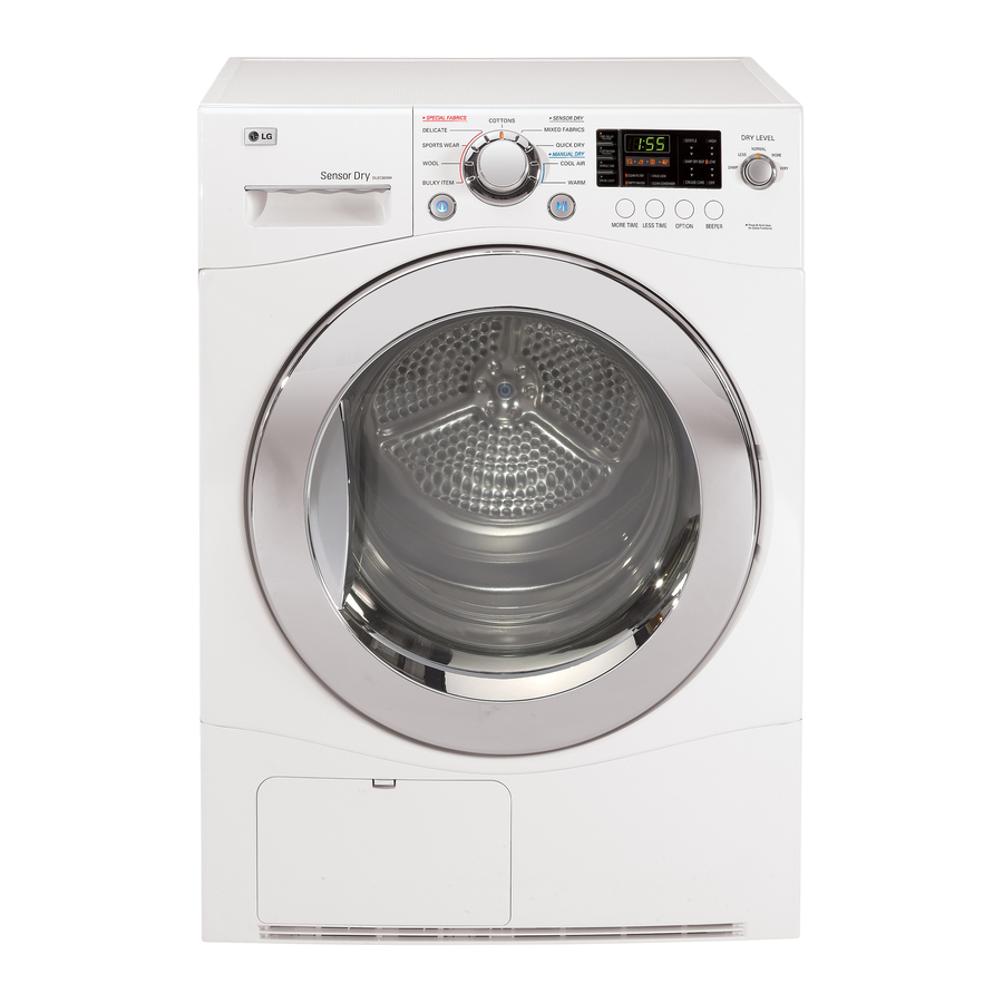
Page 7: Part Identification
PART IDENTIFICATION DLEC855W / DLEC855R Water Container Control Panel Glass Door Condenser Cover Air Ventilation Grill Accessory parts 1. Drain Hose Assembly 2. Dryer Rack Assembly P/No. : 5001EL2001A P/No. : 3751EL1002C 3. Stacking kit Assembly ( Purchased Seperately) -
Page 8: Program Cycle
https://appliancetechmanuals.com PROGRAM CYCLE TIME DELAY CUSTOM PROGRAM You can use the TIME DELAY function to delay the If you have a special combination of settings finishing time of drying cycle. that you use frequently, you can save these Maximum TIME DELAY is 19 hours. settings as a CUSTOM PROGRAM. - Page 9 https://appliancetechmanuals.com PROGRAM CYCLE *CHILD LOCK OPTION Use this option to prevent unwanted GENTLE use of the dryer or to keep cycle settings from - These are functioning to shorten or lengthen the being changed while the dryer is operating. Press cycle time by increasing or decreasing and hold the TIME DELAY button for 3 seconds to temperature.
- Page 10 https://appliancetechmanuals.com PROGRAM CYCLE Cycle Selection Table Drying Electronic Sensor Dry Cycles Level Towels, dressing gowns VERY For thick and quilted fabrics and bed linen Terry towels, tea towels, MORE For thick and quilted fabrics which do not need to be ironed towels, bed linen Bath towels, tea towels, For fabrics which do not need to be ironed...
- Page 11 https://appliancetechmanuals.com PROGRAM CYCLE COURSE MORE TIME TIME WRINKLE DAMP DRY CREASE CUSTOM LEFT TIME GENTLE BEEPER DELAY CARE BEEP CARE COURSE DETAIL LESS TIME VERY MORE COTTON NORMAL LESS DAMP MORE MIXED NORMAL FABRICS DAMP QUICK COOL AIR MANUAL WARM DELICATES SPECIAL SPORTS WEAR...
-
Page 12: Installation Instructions
https://appliancetechmanuals.com INSTALLATION INSTRUCTIONS Level the Dryer 1. Leveling the dryer is to prevent undesirable noise and vibration. When placing your dryer in an solid and level area where water is not dripping and freezing, flammable materials are not stored. 2. If the dryer is not properly level, adjust the front leveling legs up and down as necessary. - Page 13 INSTALLATION INSTRUCTIONS Stacking Kit WARNING In order to stack this dryer on an LG washing • Incorrect installation can cause serious machine, an LG stacking kit is required. accidents. • The weight of the dryer and the height of installation makes the stacking procedure too risky for one person.
-
Page 14: Maintenance Instructions
https://appliancetechmanuals.com MAINTENANCE INSTRUCTIONS Front Ventilation Grille 3. Connect drain hose Vacuum the front ventilation grill 3~4 time a year to to the kit. make sure there must be no build-up of lints or dirts which cause improper intake air flow. Moisture Sensor? This device functions to sense the moisture remaining contents of the laundry during... - Page 15 https://appliancetechmanuals.com MAINTENANCE INSTRUCTIONS CAUTION • Power cord must be unplugged before this work to avoid danger of electric shock. • The bulb itself could be very hot when the dryer just finishes its operation. So before changing the bulb, be sure that the inside of the drum is cool down.
-
Page 16: Component Testing Tips
https://appliancetechmanuals.com COMPONENT TESTING TIPS Component Test procedure Check result Remark 1. Thermostat Measure resistance by pressing Measure resistance of Safety (Manual type) Terminal to terminal button When resistance becomes Thermostat 1) Open at 170°C (-10/+5°C) Resistance value < 5Ω 2. Thermistor Cover, Front Measure resistance of Resistance value :... - Page 17 https://appliancetechmanuals.com COMPONENT TESTING TIPS Component Test procedure Check result Remark 7. Door S/W Measure resistance of the The state that Following terminal knob is Pressed is 1) Door switch knob : open opposite to open condition Terminal : “COM”- “NC” Resistance value <...
-
Page 18: Control Lay-Out
CONTROL LAY-OUT PWB ASSEMBLY DISPLAY LAY-OUT OPTION PART MODEL P/NO DLEC855W EBR50559203 DLEC855R O : Option diode(DP) applied X : Option diode(DP) not-applied PWB ASSEMBLY MAIN LAY-OUT... -
Page 19: Wiring Diagram
https://appliancetechmanuals.com ELECTRIC DRYER WIRING DIAGRAM BLACK ELECTRONIC CONTROL RLY3 WHITE RLY2 RLY1 PUMP PUMP DOOR SWITCH MOTOR ELECTRODE MOTOR SENSOR LAMP SENSOR THERMISTOR HEATER BLACK THERMOSTAT WHITE... -
Page 20: Troubleshooting
https://appliancetechmanuals.com TROUBLESHOOTING 1. This TEST should be used for Factory test/Service test. Do not use this DIAGNOSTIC TEST other than specified. 2. Activating the Heater manually with Door open may trp the Thermostat attached to the Heater, therefore do not activate it manually, (Do not press the door switch to operate the heater while the door is open) Activating the diagnostic test mode 1. - Page 21 https://appliancetechmanuals.com TROUBLESHOOTING Error Mode • : LED displays “ ” in case of the door open. The door must be closed and start Button must be pressed for re-operation. (See the 22 page) : Splay thermistor symptom. • Display Symptom tE 1 Low temperature thermistor open tE 3...
- Page 22 https://appliancetechmanuals.com TROUBLESHOOTING Power-On Power button press Led-Segment Plugged in Power button Drum not Lock:No Beeper Roating Circuit breaker Start button Lock: trip : No Beeper (Rotating) Low voltage Door Open? Door is not closed See the Page 24 Low temperature ("...
-
Page 23: Diagostic Test
https://appliancetechmanuals.com DIAGO STIC TEST Test 1 : ELECTRIC SUPPLY & CONTROL CHECK Trouble Symptom : No power to the dryer or the controller Measurement condition : Power is on. Caution] Electric shock. Please test after grounding check. Check Point Wiring Diagram... - Page 24 https://appliancetechmanuals.com DIAGOSTIC TEST Test 1 : ELECTRIC SUPPLY & CONTROL CHECK Trouble Symptom : No power to the dryer or the controller Measurement condition : Power is on. Caution] Electric shock. Please test after grounding check. Power voltage is within •...
- Page 25 https://appliancetechmanuals.com DIAGO STIC TEST Test 2 DOOR SWITCH / LAMP CHECK Trouble Symptom : Malfunction of lamp operation and door switch No operation of pump motor Displays “ “ in case of the door closed. The door must be closed and start. Measurement condition : Check if they are working while being connected to power supply.
- Page 26 https://appliancetechmanuals.com DIAGOSTIC TEST Test 2 DOOR SWITCH / LAMP CHECK Trouble Symptom : Malfunction of lamp operation and door switch No operation of pump motor Displays “ “ in case of the door closed. The door must be closed and start. Measurement condition : Check if they are working while being connected to power supply.
- Page 27 https://appliancetechmanuals.com DIAGOSTIC TEST Test 3 Motor check Trouble Symptom : Motor malfunction, Occurrence of the “Clean filter” repeatedly Measurement condition : • Power cord is unpluged. • Door is closed. • Check the user condition. - Put over load into drum? - Normally Input Voltage and Hertz? •...
- Page 28 https://appliancetechmanuals.com DIAGOSTIC TEST Test 3 Motor check Trouble Symptom : Motor malfunction, Occurrence of the “Clean filter” repeatedly Measurement condition : • Power cord is unpluged. • Door is closed. • Check the user condition. - Put over load into drum? - Normally Input Voltage and Hertz? •...
- Page 29 https://appliancetechmanuals.com DIAGOSTIC TEST Trouble Symptom : Motor malfunction, ventilation error Test 4 Heater check Trouble Symptom : Heater is not working. Drying failure. The designated temperature is not reached. Measurement condition : Power cord is unplugged. Check Point Wiring Diagram...
- Page 30 https://appliancetechmanuals.com DIAGOSTIC TEST Trouble Symptom : Motor malfunction, ventilation error Test 4 Heater check Trouble Symptom : Heater is not working. Drying failure. The designated temperature is not reached. Measurement condition : Power cord is unplugged. RLY3 RLY2 With RLY1,RLY2, RLY3 •...
- Page 31 https://appliancetechmanuals.com DIAGOSTIC TEST Test 5 Pump check Trouble Symptom : Check if pump is out of order. " Empty water" signals. Measurement condition : Power cord is unplugged. Check the hose blocked with foreign body or twist. Check Point Wiring Diagram...
- Page 32 https://appliancetechmanuals.com DIAGOSTIC TEST Test 5 Pump check Trouble Symptom : Check if pump is out of order. " Empty water" signals. Measurement condition : Power cord is unplugged. Check the hose blocked with foreign body or twist. (Measure with power on) •...
- Page 33 https://appliancetechmanuals.com DIAGOSTIC TEST Test 6 Thermister check Trouble Symptom : Poor drying performance(over-drying or no drying). Abnormal thermistor operation. Measurement condition : Power cord is unplugged. Check Point Wiring Diagram...
- Page 34 https://appliancetechmanuals.com DIAGOSTIC TEST Test 6 Thermister check Trouble Symptom : Poor drying performance(over-drying or no drying). Abnormal thermistor operation. Measurement condition : Power cord is unplugged. • Check and replace With WHITE 4 , WHITE 6 disconnected from Controller. Controller, check 1) Check disconnected 1) High temperature thermistor (Wire color : Housing or severed...
- Page 35 https://appliancetechmanuals.com DIAGOSTIC TEST Test 6 Moisture sensor check Trouble Symptom : Drying Failure Measurement condition : Power cord is unplugged. Check Point Wiring Diagram...
- Page 36 https://appliancetechmanuals.com DIAGOSTIC TEST Test 6 Moisture sensor check Trouble Symptom : Drying Failure Measurement condition : Power cord is unplugged. With NA4 disconnected from • Check Harness • Check if Sensor tips Controller, NA4 - NA4 have foreign objects resistance is unlimited? - Refer to the left picture With metal tape attached to •...
-
Page 37: Disassemble Instructions
https://appliancetechmanuals.com DISASSEMBLE INSTRUCTIONS 1. Disassemble top plate by unscrewing 2 TOP PLATE screws on the rear of the dryer. 2. After pulling drawer assembly out and DRAWER unscrew 2 screws. 3. Disassemble control panel by unscrewing 2 screws on the Rear of the panel frame. - Page 38 https://appliancetechmanuals.com DISASSEMBLE INSTRUCTIONS 4. Disassemble the lower cover by pulling to the front. DRAWER 5. Disassemble cabinet by unscrewing 2 at the top and 3 at the rear (Left and right are the same). CABINET 6. Disassemble panel frame by unscrewing PANEL FRAME 4 at the front.
- Page 39 https://appliancetechmanuals.com DISASSEMBLE INSTRUCTIONS 7-1. Disassemle the door by releasing the 2 screws. 7-2. Disassemble the door switch. 7-3. Disassemble the cabinet cover by releasing the 10 screws. 7-4. Disassemble the Door Switch. 7-5. Disassemble the cover, cabinet. DOOR CABINET COVER DOOR SWITCH 8-1.
- Page 40 https://appliancetechmanuals.com DISASSEMBLE INSTRUCTIONS 9. Disassembling the side frame by releasing 4 screws 10. Disassemble the housing of motor, heater, pump and capacitor. PUMP HOUSING MOTOR HOUSING 11-1. Disassemble the hose. DISPENSER 11-2. Disassemble the Holder from cover, rear. 11-3. Disassemble the hose.
- Page 41 https://appliancetechmanuals.com DISASSEMBLE INSTRUCTIONS 12-1. Disassemble the duct by releasing the 7 screws. 12-2. Release the durum nut using tool. 12-3. Disassemble the air guide by releasing the 1 screw. AIR GUIDE DUCT 13-1. Disassemble the COVER REAR by releasing the 2 screws. 13-2.
-
Page 42: Exploded View
https://appliancetechmanuals.com EXPLODED VIEW Control Panel & Top plate Assembly A100 A110 A114 A111 A113 A160 A112 A120 A150 A130 A140... - Page 43 https://appliancetechmanuals.com EXPLODED VIEW Cabinet Cover & Door Assembly Transparent door B103 B100 B107 B109 B106 B102 B101 B124 B215 B127 B121 B122 B140 B130 B135 B150 B125 B120...
- Page 44 https://appliancetechmanuals.com EXPLODED VIEW Base & Motor Assembly C255 C310 C320 C170 C340 C290 C330 C250 C130 C165 C160 C142 C300 C140 C150 C110 C120 C100 C230 C240 C240 C210 C230 C205 C200 C180...
- Page 45 https://appliancetechmanuals.com EXPLODED VIEW Back Cover & Drum Assembly D122 D120 D100 D110 D121 D156 D150 D263 D260 D210 D175 D200 D130 D152 D151 D157 D170...