Casio PX-720 Service Manual & Parts Manual
Hide thumbs
Also See for PX-720:
- Manual (45 pages) ,
- User manual (37 pages) ,
- Safety precautions (2 pages)

Related Manuals for Casio PX-720


Summary of Contents for Casio PX-720
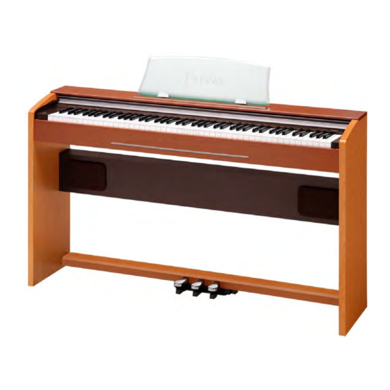
- Page 1 (without price) PX-720/PX-720C SEP. 2007 PX-720C ELECTRONIC KEYBOARD INDEX Ver. 6 : Oct. 2015...
-
Page 2: Table Of Contents
CONTENTS SPECIFICATIONS ------------------------------------------------------------------------------------------ 1 BLOCK AND WIRING DIAGRAM --------------------------------------------------------------------- 2 PCB LAYOUT ----------------------------------------------------------------------------------------------- 3 CIRCUIT DESCRIPTION --------------------------------------------------------------------------------- 4 PRINTED CIRCUIT BOARDS -------------------------------------------------------------------------- 5 DISASSEMBLY --------------------------------------------------------------------------------------------- 7 DIAGNOSTIC PROGRAM ------------------------------------------------------------------------------18 EXPLODED VIEW ----------------------------------------------------------------------------------------21 PARTS LIST ------------------------------------------------------------------------------------------------23 SCHEMATIC DIAGRAMS -------------------------------------------------------------------------------27... -
Page 3: Specifications
SPECIFICATIONS Keyboard: 88-key piano keyboard, with Touch Response Maximum Polyphony: 128 notes Tones: • Layer (excluding bass tones) • Split (Low-range bass tones only) Effects: Brilliance (−3 to +3), Reverb (4 types), chorus (4 types), Acoustic Resonance Metronome: • Beats: 0, 2, 3, 4, 6 •... -
Page 4: Block And Wiring Diagram
BLOCK AND WIRING DIAGRAM MAIN PCB (M408-MDA1) Control signal Reset IC RESET FLASH (128Mbit) D8 ~ MD15 SAD0 ~ SAD12, SDBA0,SDBA1 A1 ~ A20 RAM (64Mbit) ROM (16Mbit) SDD0 ~ SDD15 D0 ~ D15 MA0 ~ MA3 12MHz KEY CONTROLLER IC11 MD0 ~ MD15 IC10... -
Page 5: Pcb Layout
PCB LAYOUT M681-CNA1 PCB M681-CNA4 PCB Rear M681-CNA3 PCB M408-PSA1 PCB M408-MDA1 PCB M681-CNA2 PCB Components MAIN PCB M408-MDA1 MPU, Reset IC, RAM(64Mbit), FLASH memory(128Mbit), ROM(16Mbit), DAC, Key controller SUB PCB M408-PSA1 Power supply circuit, Filter, Power amplifer Console PCBs M681-CNA1 Button, Main volume M681-CNA2... -
Page 6: Circuit Description
CIRCUIT DESCRIPTION KEY MATRIX ... -
Page 7: Printed Circuit Boards
PRINTED CIRCUIT BOARDS Main PCB M408-MDA1 Sub PCB M408-PSA1 – 5 –... - Page 8 Console PCB M681-CNA1 Console PCB M681-CNA2 Console PCB M681-CNA3 Console PCB M681-CNA4 – 6 –...
-
Page 9: Disassembly
DISASSEMBLY ■ To remove main body and speaker box. *The screws come with the cap. *Do not forget to attach the screw caps when assembling. 1. Remove the Connector and Pedal cord. 2. Remove 2 screws and then the Pedal unit Pedal cord Screws Connector... - Page 10 ■ Speaker box disassembly 1. Remove the 20 screws and then the back of the speaker box. 2. Remove the 4 screws for each speaker and then take out the speakers (left and right). ■ Removing the T-BRD-UNIT. 1. Remove 18 screws and then the T-BRD unit. T-BRD unit –...
- Page 11 ■ Removing the Key cover. 1. Remove the 4 screws and the 2 stoppers on the left and right ends. Stoppers Precautions During Assembly To avoid any risk of damaging the stoppers during installation, do not use an electric screwdriver. 2.
- Page 12 ■ Removing the PCBs (M408-MDA1 PCB, M408-PSA1 PCB, M681-CNA3 PCB). 1. Remove the twist ties that hold the cables in place. 2. Remove 8 screws 3. Remove the PCB case. M408-MDA1 PCB M408-PSA1 PCB M681-CNA3 PCB – 10 –...
- Page 13 4. Remove the 11 connectors, release the lock and then remove the FPC. Connector Connector Connector Connector (Keyboard) (Pedal) (M681-CNA3) (M681-CNA2) (SPEAKER(L)) Connector (Power SW) Connector Connector Connector Connector Connector Connector (M681-CNA1) (M681-CNA1) (M408-MDA1) (M681-CNA3) (SPEAKER(R)) (M681-CNA4) 5. Remove 4 screws and the M408-MDA1 PCB. 6.
- Page 14 ■ Removing the Pedal connector. 1. Remove 2 screws and then the Pedal connector. ■ Removing the Front board. 1. Remove the 10 screws and lift up the front board. * The panel is still connected by a lead. 2. Remove the front board. Front board ■...
- Page 15 ■ To remove the CN-PANEL 2. Remove 4 screws and the CN-PANEL. CN-PANEL ■ Removing the Side block 1. Remove the 6 screws.(left and right). <The right side> <The left side> 2. Remove the side units (left and right). – 13 –...
- Page 16 ■ Disassembling the left side unit (M681-CNA1 PCB, M681-CNA2PCB) 1. Remove the side case. 2. Remove 2 screws and the M681-CNA2 unit. 3. Remove 2 nuts and the M681-CNA2 PCB. M681-CNA2 PCB 4. Remove 4 screws. 5. Remove the volume knob and the rubber key and M681-CNA1 PCB. Rubber key M681-CNA1 PCB –...
- Page 17 ■ Disassembling the right side unit (Power switch) 1. Remove the side case. 2. Remove 2 screws and the Power switch. Power switch – 15 –...
- Page 18 ■ To remove the Keyboard 1. Remove 2 screws and then 2 brackets 2. Remove 24 screws and then the KEY-BOARD ASSY. 3. Remove the keys. – 16 –...
- Page 19 Caution while assembling the keys. • Set the key as shown in figures below. 4. Remove 8 rubber keys. * One of the keys has the different length from others. How to install the rubber keys. 5. Remove 9 screws then the MCPZ-KYA1 PCB. 6.
-
Page 20: Diagnostic Program
DIAGNOSTIC PROGRAM Initial Setting 1. Connect the AC adaptor. 2. Connect the pedal. NOTE: If there is no pedal, pedal check can be skipped. 3. “Main” volume: MAX How to start diagnostic program 1. While pressing down “METRONOME”, “RECORDER”, and “/” buttons at the same time, turn the power ON. * Wait for confirmation chords C4, E4, G4 sound. - Page 21 3. ROM version check (Internal / External) Press “TONE/SETTING” button to perform the “ROM check (Internal).” The confirmation chords C4, E4, G4 sounds. Each time “▲/” button is pressed, the different LEDs light. Confirm with the lit LED. ...
- Page 22 5. MODEL check Press the “SOFT” pedal. The confirmation chord E4 sounds and “MODERN” LED lights. Press the “SOSTENUTO” pedal. The confirmation chord G4 sounds and “MODERN” LED lights. Press the “DAMPER” pedal. (ON HALF) The confirmation chord C4 sounds and “CLASSIC” LED lights. ...
-
Page 23: Exploded View
EXPLODED VIEW 43-1 36-1 – 21 –... - Page 24 51-1 51-3 51-2 51-4 51-5 52-1 52-2 52-3 52-4 52-5 Screw � Screw � 2 Clip � 2 Screw cap � 2 Screw cap � – 22 –...
-
Page 25: Parts List
PARTS LIST PX-720/PX-720C Notes: This parts list does not include the cosmetic parts, which parts are marked with item No. "R-X" in the exploded view. Contact our spare parts department if you need these parts for refurbish. 1. Prices and specifications are subject to change without prior notice. - Page 26 PX-720_BLACK_DI_120V PX-720_CHERRY_DI_120V PX-720_BLACK_DI_230V PX-720_CHERRY_DI_230V PX-720_BLACK_EU PX-720_CHERRY_EU PX-720_BLACK_UK PX-720_CHERRY_UK PX-720_BLACK_US PX-720_CHERRY_US Q'TY Price Item Parts No. Parts Code Specification Remarks Code MAIN PCB 10286863 PCB ASSY/MAIN TK-RJM508127*001 F6,F7 10122975 CHIP R-C NETWORK EZASSB516BJ F3,4,5,9, 10122976 CHIP R-C NETWORK EZASTB63ABJ 10,11 10123002 IC TC74VHC174FT(EL) 10255468 LSI MB91F036PFF-GE1...
- Page 27 RJM507971-001V01 10281955 SIDE BLOCK/LEFT RJM507971-002V01 10281445 RUBBER KEY RJM505783-002V02 10286859 PCB ASSY/CNA1 TK-RJM508131*001 IC601,602 10279863 IC TC74VHC164FT(EL.K) VR601 10273791 VARIABLE RESISTOR F-09KGH-CASIO-1 D607,608, 23153132 DIODE 1SS133T-77 609,610 D401-406 10171338 LED LT2P71-81-M1-S06 SW601-607 10228658 TACT SWITCH THVV502GAA 10286860 PCB ASSY/CNA2 TK-RJM508133*001...
- Page 28 PX-720_BLACK_DI_120V PX-720_CHERRY_DI_120V PX-720_BLACK_DI_230V PX-720_CHERRY_DI_230V PX-720_BLACK_EU PX-720_CHERRY_EU PX-720_BLACK_UK PX-720_CHERRY_UK PX-720_BLACK_US PX-720_CHERRY_US Q'TY Price Item Parts No. Parts Code Specification Remarks Code STAND 10286839 BOARD ASSY/LEFT TK-RJM508087*001 10286840 BOARD ASSY/LEFT TK-RJM508087*002 C For Korea 10286841 BOARD ASSY/LEFT TK-RJM508087*003 10286842 BOARD ASSY/LEFT TK-RJM508087*004 C For Korea 51-1 10246609 BOLT...
-
Page 29: Schematic Diagrams
SCHEMATIC DIAGRAMS Main PCB M408-MDA1 – 27 –... - Page 30 – 28 –...
- Page 31 Sub PCB M681-PSA1 – 29 –...
- Page 32 Console PCB M681-CNA1 – 30 –...
- Page 33 Console PCBs M681-CNA2, CNA3, CNA4 Console PCB M681-CNA2 Console PCB M681-CNA3 Console PCB M681-CNA4 – 31 –...
- Page 34 Ver. 5 : Jan. 2010 • Correction of the EXPLODED VIEW (P21) • Correction of the PARTS LIST (P25) Ver. 6 : Oct. 2015 • Correction of the PARTS LIST (P25) CASIO COMPUTER CO.,LTD. Overseas Service Division 6-2, Hon-machi 1-Chome Shibuya-ku, Tokyo 151-8543, Japan...