Table of Contents
Advertisement
Available languages
Available languages
Quick Links
PANNELLO COMANDI
CONTROL PANEL
IT
ISTRUZIONI DI USO E MANUTENZIONE
Istruzioni originali in lingua italiana
EN
USE AND MAINTENANCE INSTRUCTIONS
Translation of the original instructions in Italian
VALDINOCI LUIGI
S.p.a.
www.valdinoci.it
Via Antico Acquedotto, 19 • 47122 Forlì • ITALIA • Tel. +39 0543 720 909 •
• motori@valdinoci.it
Advertisement
Chapters
Table of Contents

Summary of Contents for Kohler ATS45
- Page 1 PANNELLO COMANDI CONTROL PANEL ISTRUZIONI DI USO E MANUTENZIONE Istruzioni originali in lingua italiana USE AND MAINTENANCE INSTRUCTIONS Translation of the original instructions in Italian VALDINOCI LUIGI S.p.a. www.valdinoci.it Via Antico Acquedotto, 19 • 47122 Forlì • ITALIA • Tel. +39 0543 720 909 • •...
-
Page 2: Table Of Contents
Specifiche tecniche pannello comandi .......4 Cablaggio interno pannello comandi ........5 Descrizione funzioni Pin connettori JP1 ......6 Dimensioni strumento ATS45 ..........7 Specifiche tecniche strumento ATS45.........7 DESCRIZIONE FUNZIONALE STRUMENTO ATS45 ....8 Pagina PRINCIPALE ..............9 Altre pagine ................10 GESTIONE RIGENERAZIONE ..........11 DESCRIZIONE DEI MENU ...........12 Menu BASE ................12... -
Page 3: Informazioni Tecniche
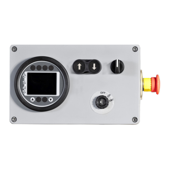
Il pannello comandi permette l’accensione del motore tramite il commutatore di avviamento, la visualizzazione di spie e numerosi parametri del motore tramite lo strumento ATS45, la regolazione dei giri motore a piccoli step tramite due pulsanti o la selezione di due setpoint preimpostati di giri tramite un selettore. Inoltre è possibile lo spegnimento del motore in condizioni di emergenza attraverso l’apposito fungo di arresto. -
Page 4: Dimensioni Pannello Comandi
INFORMAZIONI TECNICHE Dimensioni pannello comandi Specifiche tecniche pannello comandi Peso complessivo 2,8 kg Temperatura di esercizio -20°C ÷ +70°C Alimentazione 8÷30 Vdc... -
Page 5: Cablaggio Interno Pannello Comandi
INFORMAZIONI TECNICHE Cablaggio interno pannello comandi... -
Page 6: Descrizione Funzioni Pin Connettori Jp1
Utilizzabile per segnalare un errore macchina da parte del cliente. FREE IN 2 (ingresso digitale negativo). Quando è messo a terra, appare nella pagina principale dell'ATS45 la spia di Allarme generico 2 (rif. box spie Pin 10 display 1 pag. 9). -
Page 7: Dimensioni Strumento Ats45
INFORMAZIONI TECNICHE Dimensioni strumento ATS45 14,5 37,7 68,1 Specifiche tecniche strumento ATS45 Peso complessivo 320 g Grado di protezione elettronica IP 65 Grado di protezione morsettiere IP 44 Temperatura di esercizio -20°C ÷ +70°C Alimentazione 8÷30 Vdc Consumo fisso 160 mA... -
Page 8: Descrizione Funzionale Strumento Ats45
Pulsante "freccia su" (FSU). Tasto di incremento, Funzione ESC se tenuto premuto. Pulsante "freccia giù" (FGIU). Tasto di decremento, Funzione ENTER se tenuto premuto. Uso dei tasti freccia dello strumento ATS45 - Premere i tasti rif. 8 o 9 per accedere alla varie pagine visualizzate nel display dello strumento. -
Page 9: Pagina Principale
DESCRIZIONE FUNZIONALE STRUMENTO ATS45 Pagina PRINCIPALE Pos. Descrizione Box spie display 1 Barra di livello carburante (%) Contaore di lavoro motore (h) Contagiri motore (rpm) Barra temperatura acqua motore (°C) Box spie display 2 Nella pagina principale sono visualizzati i giri motore, espressi in rpm, sia attraverso un valore numerico che attraverso una barra grafica circolare. -
Page 10: Altre Pagine
- sono presenti i valori del consumo istantaneo di combustibile PARAMETRI MOTORE del motore, la percentuale di carico, la pressione dell’olio e il setpoint RPM che l’ATS45 richiede alla ECU; - sono presenti i valori della tensione batteria, livello di riempimento del serbatoio combustibile, temperatura... -
Page 11: Gestione Rigenerazione
GESTIONE RIGENERAZIONE GESTIONE RIGENERAZIONE Avvertenza • La seguente procedura è applicabile solo a motori provvisti di DPF. - Durante il normale funzionamento del motore, potrebbe apparire nella pagina principale la spia “Gas di scarico ad alta temperatura”. Spesso indica che una rigenerazione automatica attiva è in corso. Per evitare che si renda necessaria una rigenerazione forzata del filtro antiparticolato a macchina ferma, si consiglia di continuare a lavorare fino allo spegnimento della spia;... -
Page 12: Descrizione Dei Menu
Nel menu base è possibile accedere ai seguenti parametri: Pagina Descrizione Selezionando questo parametro è possibile modificare la lingua dell’ATS45 (lingue disponibili: Italiano ed Inglese). LINGUA Selezionando questo parametro è possibile impostare il tempo (minuti) dopo il quale, nel caso di inattività... -
Page 13: Contatore Decrementale
DESCRIZIONE DEI MENU Contatore decrementale È presente un contatore decrementale che avvisa l'operatore quando è necessario eseguire interventi di manutenzione (ore iniziali countdown di default: 500). Alla scadenza del tempo previsto, appare un messaggio che ricorda di effettuare il service. - Dopo aver effettuato il tagliando, per far scomparire il messaggio è... -
Page 14: Menu Avanzato
FSU (rif. 8 pag. 8) per confermare la cifra. Dal menu avanzato è possibile modificare i parametri di gestione e controllo dello strumento ATS45. Il menu avanzato è composto da due sottomenu aggiuntivi rispetto al menu base. - Page 15 DESCRIZIONE DEI MENU Entrando in questo menu è possibile configurare i parametri relativi alla sonda di livello del carburante: - 1 – S. ALLARME: percentuale di livello del carburante sotto la quale scatta l’allarme livello carburante (impostare a 0 % per disabilitare l’allarme) - 2 –...
-
Page 16: Menu Impostazioni
ON indica che i giri motore sono trasmessi dall’ATS45 alla ECU attraverso comunicazione CANBUS. - 2 – GIRI MIN: valore minimo impostabile in RPM dei giri motore (utilizzato solo con TSC1 = ON) - 3 –... - Page 17 Control panel dimensions ..........19 Control panel technical specifications ......19 Control panel internal wiring ..........20 JP1 connector pin functions ..........21 ATS45 device dimensions ..........22 ATS45 device technical specifications ......22 ATS45 FUNCTIONS ..............23 ATS45 device arrow buttons ..........23 MAIN page ................24 Other pages................25 REGENERATION MANAGEMENT ........26...
-
Page 18: Technical Information
The control panel lets you start the engine through the ignition switch. It shows the warning lights and other parameters by means of the ATS45 device. It lets you adjust the engine rpm in small steps by means of two buttons, select two preset rpm values using the selector switch, or stop the engine in case of an emergency by pressing the emergency stop mushroom-head button. -
Page 19: Control Panel Dimensions
TECHNICAL INFORMATION Control panel dimensions Control panel technical specifications Total weight 2.8 kg Operating temperature -20°C ÷ +70°C Power supply 8÷30 Vdc... -
Page 20: Control Panel Internal Wiring
TECHNICAL INFORMATION Control panel internal wiring... -
Page 21: Jp1 Connector Pin Functions
When powered by a positive signal (range 8-30 V), the General Alarm 1 warning light (ref. Display 1 warning Pin 4 lights box, p. 24) is displayed on the main page of ATS45. It can be used by the client to inform of a machine error. -
Page 22: Ats45 Device Dimensions
TECHNICAL INFORMATION ATS45 device dimensions 14,5 37,7 68,1 ATS45 device technical specifications Total weight 320 g Electronic equipment protection class IP 65 Terminal board protection class IP 44 Operating temperature -20°C ÷ +70°C Power supply 8÷30 Vdc Fixed consumption 160 mA... -
Page 23: Ats45 Functions
"Arrow down" (FGIU) button. It lets you decrease a value. It has the ENTER function, if you hold it pressed. ATS45 device arrow buttons - Press the buttons ref. 8 or 9 to open the pages displayed on the device screen. -
Page 24: Main Page
ATS45 FUNCTIONS MAIN page Pos. Description Display 1 warning lights box Fuel level bar (%) Engine hour meter (h) Engine rev counter (rpm) Engine water temperature bar (°C) Display 2 warning lights box The engine speed (rpm) is displayed on the main page through a number and a dial chart. Two vertical bars give the instant fuel level (%) and engine water temperature (°C). -
Page 25: Other Pages
ATS45 FUNCTIONS Other pages Shortly press the UP button (ref. 8, page 23) or the DOWN button (ref. 9, page 23) to open the other pages available in ATS45, which are the following: Page Description - It displays the soot and ash percent load of the Diesel Particulate Filter (DPF). -
Page 26: Regeneration Management
REGENERATION MANAGEMENT REGENERATION MANAGEMENT Warning • The following procedure applies to DPF-equipped engines only. - During normal engine running the warning light “High exhaust gas temperature” may appear on the main page. It often indicates that an active automatic regeneration is underway. - To avoid the need for a forced regeneration of the DPF when the machine is stopped, it is recommended to continue to work until the warning light switches off. -
Page 27: Menu Overview
From the basic menu you can access the following parameters: Page Description Select this parameter to change the language in ATS45 (Italian or English are available). LANGUAGE Select this parameter to set the time (minutes) after which the device returns to the main page in case of inactivity - the operator does not press any button. -
Page 28: Decrement Counter
MENU OVERVIEW Decrement counter A decrement counter feature is implemented to warn the operator when scheduled maintenance shall be carried out (default counter setting: first 500 hours). When a scheduled interval is reached, a message appears to prompt you to carry out maintenance. - To cancel the message after maintenance, press the UP or DOWN button for about 5 seconds. -
Page 29: Advanced Menu
To open the advanced menu, input the password “5 4 8” in the password input page. From this menu it is possible to modify the parameters for the management and control of ATS45. Unlike the basic menu, the advanced menu has also two submenus. - Page 30 MENU OVERVIEW From this menu you can set the parameters of the fuel level sensor: - 1 – ALARM THRESHOLD: fuel percent level below which the fuel level alarm is triggered (set it to 0% if you want to disable the alarm). - 2 –...
-
Page 31: Settings Menu
- 8 - RESERVED - 9 - REGEN LOAD: load above which power to OUT1 is turned off (output 8A in ATS45) - 10 - HIGH LOAD: load below which power to OUT2 is turned off (output 1B in ATS45). - Page 32 NOTES ................................................................................................................................................................................................................................................................................................................................................................................................................................................................................................................................................................................................................................................................................................................................................................................................................................................................................................................................................................................................................................................................................................................................................................................................................................................................
- Page 33 ................................................................................................................................................................................................................................................................................................................................................................................................................................................................................................................................................................................................................................................................................................................................................................................................................................................................................................................................................................................................................................................................................................................................................................................................................................................................................................
- Page 34 ................................................................................................................................................................................................................................................................................................................................................................................................................................................................................................................................................................................................................................................................................................................................................................................................................................................................................................................................................................................................................................................................................................................................................................................................................................................................................................
- Page 35 Istruzioni originali in lingua ITALIANA: Questo documento è stato emesso originariamente in lingua Italiana. In presenza di eventuali controversie dovute alle traduzioni il testo di riferimento sarà unicamente la versione italiana. Original instructions in ITALIAN: This document was originally issued in Italian. Should there be any dispute due to translations, the authoritative version remains solely the Italian version.
- Page 36 CODICE/CODE REV. DATA/DATE REV. AM01 09/2021 VALDINOCI LUIGI S.p.a. www.valdinoci.it Via Antico Acquedotto, 19 • 47122 Forlì • ITALIA • Tel. +39 0543 720 909 • • motori@valdinoci.it...