Table of Contents
Advertisement
Quick Links
Advertisement
Table of Contents
Troubleshooting

Related Manuals for Gigabyte GA-F2A88X-D3HP


Summary of Contents for Gigabyte GA-F2A88X-D3HP
- Page 1 GA-F2A88X-D3HP User's Manual Rev. 1002 12ME-F2883HP-1002R For more product details, please visit GIGABYTE's website. To reduce the impacts on global warming, the packaging materials of this product are recyclable and reusable. GIGABYTE works with you to protect the environment.
- Page 3 No part of this manual may be reproduced, copied, translated, transmitted, or published in any form or by any means without GIGABYTE's prior written permission. In order to assist in the use of this product, GIGABYTE provides the following types of documentations: For quick set-up of the product, read the Quick Installation Guide included with the product.
-
Page 4: Table Of Contents
Table of Contents Box Contents ........................6 Optional Items .........................6 GA-F2A88X-D3HP Motherboard Layout .................7 Chapter 1 Hardware Installation ..................9 Installation Precautions ..................9 ..................10 Installing the APU and APU Cooler ..............13 1-3-1 Installing the APU ....................13 1-3-2 Installing the APU Cooler ..................15 Installing the Memory .................. - Page 5 Chapter 5 Unique Features ...................67 BIOS Update Utilities ..................67 5-1-1 Updating the BIOS with the Q-Flash Utility .............67 5-1-2 Updating the BIOS with the @BIOS Utility .............70 APP Center ....................71 5-2-1 EasyTune........................72 5-2-2 System Information Viewer ..................73 5-2-3 Smart TimeLock......................74 ....................75 5-2-5...
-
Page 6: Box Contents
Box Contents GA-F2A88X-D3HP motherboard Motherboard driver disk User's Manual Quick Installation Guide Four SATA cables The box contents above are for reference only and the actual items shall depend on the product package you obtain. The box contents are subject to change without notice. -
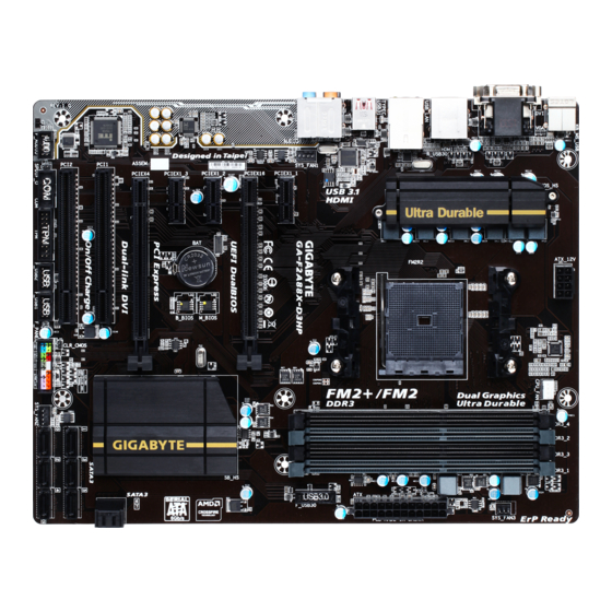
Page 7: Ga-F2A88X-D3Hp Motherboard Layout
GA-F2A88X-D3HP Motherboard Layout ATX_12V KB_MS_USB CPU_FAN SYS_FAN3 Socket FM2+ HDMI ® USB_LAN GbE LAN USB31 TYPEC ASMedia USB 3.1 ® Controller AUDIO SYS_FAN1 PCIEX1_1 GA-F2A88X-D3HP PCIEX16 PCIEX1_2 M_BIOS CODEC PCIEX1_3 B_BIOS PCIEX4 AMD A88X ® PCI1 SATA3 PCI2 F_AUDIO SPDIF_O... - Page 8 - 8 -...
-
Page 9: Chapter 1 Hardware Installation
Chapter 1 Hardware Installation Installation Precautions The motherboard contains numerous delicate electronic circuits and components which can become manual and follow these procedures: Prior to installation, make sure the chassis is suitable for the motherboard. warranty sticker provided by your dealer. These stickers are required for warranty validation. Always remove the AC power by unplugging the power cord from the power outlet before installing or removing the motherboard or other hardware components. - Page 10 Support for DD 3 2133 1866 1600 1333 MHz memory modules Support for AMD Memory Pro le (AMP Extreme Memory Pro le (XMP memory modules (Go to GIGABYTE's website for the latest supported memory speeds and memory modules. Onboard Integrated Graphics Processor:...
- Page 11 Multi-Graphics Support for 2-Way AMD CrossFire ™ Technology Technology Support for AMD Dual Graphics technology Only A series APUs support AMD Dual Graphics. Storage Interface Chipset: 8 x SATA 6Gb s connectors Support for AID 0, AID 1, AID 5, AID 10, and JBOD Chipset: 4 USB 3.0 2.0 ports (2 ports on the back panel, 2 ports available through the internal USB header...
- Page 12 Form Factor ATX Form Factor; 30.5cm x 23.5cm prior notice. Please visit GIGABYTE's website for support lists of CPU, memory modules, and SSDs. Please visit the Support\Utility List page on GIGABYTE's website to download the latest version of apps. Hardware Installation...
-
Page 13: Installing The Apu And Apu Cooler
1-3-1 Installing the APU A Small Triangle Marking Denotes Pin FM2+ Socket One of the Socket A Small Triangle Marking Denotes APU Pin One Please visit GIGABYTE's website for details on hardware installation. - 13 - Hardware Installation... - Page 14 B. Follow the steps below to correctly install the APU into the motherboard APU socket. Before installing the APU, make sure to turn off the computer and unplug the power cord from the power outlet to prevent damage to the APU. APU orientation if this occurs.
-
Page 15: Installing The Apu Cooler
1-3-2 Installing the APU Cooler Follow the steps below to correctly install the APU cooler on the motherboard. Step 1: Step 2: Apply an even and thin layer of thermal grease on Hook the APU cooler clip to the mounting lug on the surface of the installed APU. -
Page 16: Installing The Memory
Installing the Memory Make sure that the motherboard supports the memory. It is recommended that memory of the same capacity, brand, speed, and chips be used. Always turn off the computer and unplug the power cord from the power outlet before installing the memory to prevent hardware damage. -
Page 17: Installing A Memory
1-4-2 Installing a Memory Before installing a memory module, make sure to turn off the computer and unplug the power cord from the power outlet to prevent damage to the memory module. DDR3 and DDR2 DIMMs are not compatible to each other or DDR DIMMs. Be sure to install DDR3 DIMMs on this motherboard. Notch your memory modules in the memory sockets. -
Page 18: Installing An Expansion Card
Installing an Expansion Card Make sure the motherboard supports the expansion card. Carefully read the manual that came with your expansion card. Always turn off the computer and unplug the power cord from the power outlet before installing an expansion card to prevent hardware damage. PCI Express x1 Slot PCI Express x16 Slot PCI Slot... - Page 19 Combining the onboard GPU with a discrete graphics card, AMD's Dual Graphics technology can provide Dual Graphics system. A. System Requirements - AMD A series processor - An AMD Dual Graphics technology-supported motherboard and correct driver Step 1: Observe the steps in "1-5 Installing an Expansion Card" and install an AMD Dual Graphics technology-supported graphics card on the PCIEX16 slot.
-
Page 20: Back Panel Connectors
Back Panel Connectors USB 2.0/1.1 Port PS/2 Keyboard/Mouse Port D-Sub Port The D-Sub port supports a 15-pin D-Sub connector and supports a maximum resolution of 1920x1200 D-Sub connection to this port. DVI-D Port (Note 1) Connect a monitor that supports DVI-D connection to this port. Please note that the actual resolutions supported are dependent on the monitor being used and support for 2560x1600 resolution requires both a monitor and cable that support Dual Link DVI. - Page 21 B. Playback of Blu-ray Disc ™ In order to get better playback quality, when playing the Blu-ray Disc ™ , refer to the recommended system AMD A series processors BIOS Setup: At least 512 MB of UMA Frame Buffer Size (refer to Chapter 2, "BIOS Setup," "Peripherals\ Playback software: CyberLink PowerDVD 10.0 or later (Note: Please ensure Hardware Acceleration is enabled.
-
Page 22: Internal Connectors
Internal Connectors ATX_12V F_PANEL F_AUDIO CPU_FAN SPDIF_O SYS_FAN1/SYS_FAN2/SYS_FAN3 F_USB30 F_USB1/F_USB2 SATA3 0/1/2/3/4/5/6/7 CLR_CMOS First make sure your devices are compliant with the connectors you wish to connect. Before installing the devices, be sure to turn off the devices and your computer. Unplug the power cord from the power outlet to prevent damage to the devices. - Page 23 1/2) ATX_12V/ATX (2x4 12V Power Connector and 2x12 Main Power Connector) With the use of the power connector, the power supply can supply enough stable power to all the components off and all devices are properly installed. The power connector possesses a foolproof design. Connect the power supply cable to the power connector in the correct orientation.
- Page 24 3/4) CPU_FAN/SYS_FAN1/SYS_FAN2/SYS_FAN3 (Fan Headers) The speed control function requires the use of a fan with fan speed control design. For optimum heat dissipation, it is recommended that a system fan be installed inside the chassis. CPU_FAN: Pin No. +12V Sense CPU_FAN Speed Control Pin No.
- Page 25 6) SATA3 0/1/2/3/4/5/6/7 (SATA 6Gb/s Connectors) Pin No. 1 3 5 0 2 4 To enable hot-plugging for the SATA ports, refer to Chapter 2, "BIOS Setup," "Peripherals\SB SATA 7) CLR_CMOS (Clear CMOS Jumper) the CMOS values, use a metal object like a screwdriver to touch the two pins for a few seconds. Open: Normal Short: Clear CMOS Values Always turn off your computer before clearing the CMOS values.
- Page 26 8) F_PANEL (Front Panel Header) on the chassis to this header according to the pin assignments below. Note the positive and negative pins before connecting the cables. Power LED Power Switch Speaker Hard Drive Power LED Activity LED Switch Chassis Intrusion Header PLED/PWR_LED System Status LED...
- Page 27 9) F_AUDIO (Front Panel Audio Header) your chassis front panel audio module to this header. Make sure the wire assignments of the module connector match the pin assignments of the motherboard header. Incorrect connection between the module connector and the motherboard header will make the device unable to work or even damage it. For HD Front Panel Audio: For AC'97 Front Panel Audio: Pin No.
- Page 28 11) F_USB30 (USB 3.0/2.0 Header) Pin No. Pin No. VBUS SSTX2+ SSTX1- SSTX2- SSTX1+ VBUS No Pin 12) F_USB1/F_USB2 (USB 2.0/1.1 Headers) optional USB bracket. For purchasing the optional USB bracket, please contact the local dealer. Pin No. USB DX- USB DY- USB DX+ USB DY+...
- Page 29 13) COM (Serial Port Header) The COM header can provide one serial port via an optional COM port cable. For purchasing the optional COM port cable, please contact the local dealer. Pin No. NDCD- NSIN NSOUT NCTS- No Pin 15) TPM (Trusted Platform Module Header) Pin No.
- Page 30 Hardware Installation - 30 -...
-
Page 31: Chapter 2 Bios Setup
To access the BIOS Setup program, press the <Delete> key during the POST when the power is turned on. To upgrade the BIOS, use either the GIGABYTE Q-Flash or @BIOS utility. Q-Flash allows the user to quickly and easily upgrade or back up BIOS without entering the operating system. -
Page 32: Startup Screen
Startup Screen The following startup Logo screen will appear when the computer boots. Function Keys Press the <Delete> key to enter BIOS Setup or to access the Q-Flash utility in BIOS Setup. Press the <F9> key to display your system information. arrow key <... -
Page 33: The Main Menu
The Main Menu On the main menu of the BIOS Setup program, press arrow keys to move among the items and press <Enter> to accept or enter a sub-menu. Or you can use your mouse to select the item you want. Setup Menus Enter Q-Flash Select Default... - Page 34 M.I.T. to CPU, chipset, or memory and reduce the useful life of these components. This page is for advanced users only and we recommend you not to alter the default settings to prevent system instability or other unexpected results. (Inadequately altering the settings may result in system's failure to boot. If This section provides information on the BIOS version, CPU base clock, CPU frequency, memory frequency, total memory size, CPU temperature, Vcore, and memory voltage.
- Page 35 M.I.T. Current Status Advanced Frequency Settings CPU Clock Control Allows you to manually set the CPU base clock and PCIe bus frequency in 1 MHz increments. (Default: It is highly recommended that the CPU frequency be set in accordance with the CPU Processor Graphics Clock Allows you to set the onboard graphics clock.
- Page 36 Advanced CPU Core Features CPU Clock Ratio, CPU Frequency The settings above are synchronous to those under the same items on the Advanced Frequency Settings menu. Core Performance Boost (Note) Turbo Performance Boost Ratio Core Performance Boost Ratio Allows you alter the ratio for the CPB. The adjustable range is dependent on the CPU being installed. Enabled Lets the AMD Cool'n'Quiet driver dynamically adjust the CPU clock and VID to reduce Disabled...
- Page 37 CPU core Control Automatic mode allows the BIOS (Note) enabled. (Note) System Memory Multiplier Allows you to set the system memory multiplier. Auto sets memory multiplier according to memory SPD Memory Frequency (MHz) This value is automatically adjusted according to the CPU Clock Control and System Memory Multiplier settings.
- Page 38 Advanced Memory Settings (Note) , System Memory Multiplier, Memory Frequency(MHz) The settings above are synchronous to those under the same items on the Advanced Frequency Settings menu. Memory Timing Mode Manual and Advanced Manual allows the Channel Interleaving, Rank Interleaving, and memory timing When using a non-XMP memory module or Extreme Memory Pro le (X.M.P.) is set to Disabled, the value Extreme Memory Pro le (X.M.P.) is set to Pro le1 or Pro le2, the value is displayed according to the SPD data on the XMP memory.
- Page 39 Channel A/B Memory Sub Timings This sub-menu provides memory timing settings for each channel of memory. The respective timing setting Memory Timing Mode is set to Manual or Advanced Manual. Note: Your system may become unstable or fail to boot after you make changes on the memory timings. If this occurs, please reset the board to default values by loading optimized defaults or clearing the CMOS values.
- Page 40 PC Health Status Reset Case Open Status Enabled Clears the record of previous chassis intrusion status and the Case Open "No" at next boot. Case Open Displays the detection status of the chassis intrusion detection device attached to the motherboard CI clear the chassis intrusion status record, set Reset Case Open Status to Enabled, save the settings to the CMOS, and then restart your system.
- Page 41 CPU Vcore/DRAM Voltage/+3.3V/+5V/+12V Displays the current system voltages. CPU/System Temperature CPU/System Fan Speed CPU Temperature Warning Sets the warning threshold for CPU temperature. When temperature exceeds the threshold, BIOS will emit F, 70 F, 80 F, 90 CPU/System Fan Fail Warning Allows the system to emit warning sound if the CPU fan or system fan are not connected or fail.
- Page 42 Miscellaneous Settings Allows you to set the operation mode of the PCI Express slots to Gen 1, Gen 2, or Gen 3. Actual operation Auto 3DMark01 Boost BIOS Setup - 42 -...
-
Page 43: System Information
System Information This section provides information on your motherboard model and BIOS version. You can also select the default language used by the BIOS and manually set the system time. System Language Selects the default language used by the BIOS. System Date value. -
Page 44: Bios Features
BIOS Features Boot Option Priorities Boot Option #1 Boot Option #2 Hard Drive BBS Priorities submenu will be presented here. string. Or if you want to install an operating system that supports GPT partitioning such as Windows 7 64-bit, select BIOS Setup - 44 -... - Page 45 A password is required for booting the system and for entering the BIOS Setup Full Screen LOGO Show Allows you to determine whether to display the GIGABYTE Logo at system startup. Disabled skips the Fast Boot Enables or disables Fast Boot to shorten the OS boot process. Ultra Fast provides the fastest bootup VGA Support Allows you to select which type of operating system to boot.
- Page 46 CSM Support Never Disables UEFI CSM and supports UEFI BIOS boot process only. Windows 8 Features is set to Windows 8 or Windows 8 WH L. Boot Mode Selection Allows you to select which type of operating system to boot. CSM Support is set to Always.
- Page 47 Administrator Password BIOS Setup. Differing from the user password, the administrator password allows you to make changes to all BIOS settings. User Password Setup. However, the user password only allows you to make changes to certain BIOS settings but not all. To cancel the password, press <Enter>...
-
Page 48: Peripherals
Peripherals IOMMU OnChip USB Controller HD Audio Azalia Device If you wish to install a 3rd party add-in audio card instead of using the onboard audio, set this item to Disabled. Legacy USB Support XHCI Hand-off Determines whether to enable XHCI Hand-off feature for an operating system without XHCI Hand-off EHCI Hand-off Determines whether to enable EHCI Hand-off feature for an operating system without EHCI Hand-off Port 60/64 Emulation... - Page 49 Onboard USB3.1 Controller (ASMedia ® USB 3.1 Controller) Enables or disables the ASMedia ® Primary Video Device card or the onboard graphics. display. Integrated Graphics Enables or disables the onboard graphics function. Auto The BIOS will automatically enable or disable the onboard graphics depending on Disabled Disables the onboard graphics.
-
Page 50: Power Management
Power Management Resume by Alarm If enabled, set the date and time as following: Note: When using this function, avoid inadequate shutdown from the operating system or removal of the AC power, or the settings may not be effective. HPET Timer Soft-Off by PWR-BTTN Delay 4 Sec. - Page 51 Power On Password Set the password when Power On By Keyboard is set to Password. Press <Enter> on this item and set a password with up to 5 characters and then press <Enter> to accept. To turn on the system, enter the password and press <Enter>. Note: To cancel the password, press <Enter>...
-
Page 52: Save & Exit
Save & Exit Save & Exit Setup Press <Enter> on this item and select Yes. This saves the changes to the CMOS and exits the BIOS Setup program. Select No or press <Esc> to return to the BIOS Setup Main Menu. Exit Without Saving Press <Enter>... - Page 53 RAID Levels RAID 0 RAID 1 RAID 5 RAID 10 Minimum Number of Hard Drives Array Capacity Number of hard Size of the smallest (Number of hard (Number of hard drive smallest drive the smallest drive smallest drive Fault Tolerance Before you begin At least two SATA hard drives (to ensure optimal performance, it is recommended that you use two hard drives Windows setup disk.
- Page 54 Step 1: OnChip SATA Channel is enabled under OnChip SATA Type to RAID set OnChip SATA Type to RAID and set OnChip SATA Port4-7 Type to As SATA Type Figure 1 Step 2: The BIOS Setup menus described in this section may differ from the exact settings for your motherboard. The actual BIOS Setup menu options you will see shall depend on the motherboard you have and the BIOS version.
- Page 55 \BootDrv\UEFI RAID Utility folder in your motherboard driver Step 1: In BIOS Setup, go to BIOS Features and set Windows 8 Features to Windows 8 and CSM Support to Never. Figure 2 Running the UEFI RAID Utility You can enter the commands at Shell or level (x EFI Shell version 2.31 [4.653] Current running mode 1.1.2...
- Page 56 Checking Disk Information LIST and DISK LIST displayed on the screen. rcadm -M -qa fs0:\> rcadm -M -qa Figure 4 Creating a RAID Array succeeded, the message which says "created sucessfully" will appear. rcadm -C -r0 -d 0 1 -s 40000 ("C"= size allowed, do not enter "s x0000 fs0:\>rcadm -C -r0 -d 0 1 -s 40000...
- Page 57 Deleting an Array To delete an array, enter the following commands and press <Enter>. rcadm -D -a 1 ("D"= YES to delete or NO to cancel, and then press <Enter>. fs0:\>rcadm -D -a 1 Delete Array 1, are you sure?(YES, NO): yes deleting array 1 deleting array //./Core1/Route0/Device 1 fs0:\>...
- Page 58 Steps: After the POST memory test begins and before the operating system boot begins, look for a message which AMD-RAID Controller BIOS (6.1.4-00059) (c) 2012-2013 Advanced Micro Devices, Inc. * BIOS defaults restored. * 1--Legacy, 79GB, Normal (NA) 2--Legacy, 79GB, Normal (NA) Figure 8 Creating a RAID Array To create a new array, press <Enter>...
- Page 59 The selection bar will move to the Disks section on the right of the screen. Select the hard drives to be included drive will be shown in green. To use all of the hard drives, simply press <A> to select all. Then press <Enter> and the selection bar will move to the User Input RAID0: Stripe set - distributes space across disks for higher performance Arrays...
- Page 60 Read and Write-back Caching. (Some data may be lost in a crash) Arrays 0-00, 79GB, Ready 1-01, 79GB, Ready Create Array Disks: 0, 1 Type: RAID 0 Total Size: 158GB Cachin Mode: Read/Write User Input Select Caching Mode Available Keys Read/Write <...
- Page 61 Deleting an Array The Delete Array(s) menu option allows for deletion of disk array assignments. array type, the disk members, and stripe block size in case you wish to undo a deletion. 1. Select Delete Array(s) in the Main Menu and press <Enter>. 2.
- Page 62 Installing the SATA RAID/AHCI Driver and Operating System With the correct BIOS settings, you are ready to install the operating system. A. Installing Windows Step 1: driver folder under BootDrv in the driver disk depending on your Windows version, for example: Windows 10 driver folder: "BootDrv\Hw10"...
- Page 63 to use a new drive of equal or greater capacity. The procedures below assume a new drive is added to replace driver disk. After restarting your computer, switch to Windows desktop mode.Then double-click the RAIDXpert2 Step 2: In the Disk Devices section, left-click your mouse Step 1: twice on the newly-added hard drive.
- Page 64 - 64 -...
-
Page 65: Chapter 4 Drivers Installation
Chapter 4 Drivers Installation After installing the operating system, insert the motherboard driver disk into your optical drive. Click on the message "Tap to choose what happens with this disc" on the top-right corner of the Run.exe." (Or go to My Computer, double-click the optical drive and ex- ecute the Run Drivers &... -
Page 66: Application Software
Application Software This page displays the apps that GIGABYTE develops and some free software. You can select the apps you want and click the Install icon to begin the installation. Information This page provides detailed information on the drivers on the driver disk. The Contact page provides contact... -
Page 67: Chapter 5 Unique Features
Unique Features BIOS Update Utilities ™ ™ GIGABYTE motherboards provide two unique BIOS update tools, Q-Flash and @BIOS . GIGABYTE Q-Flash and @BIOS are easy-to-use and allow you to update the BIOS without the need to enter MS-DOS mode. ™... - Page 68 B. Updating the BIOS In the main menu of Q-Flash, use the keyboard or mouse to select an item to execute. When updating the Step 1: Update BIOS From Drive. The Save BIOS to Drive to an independent SATA controller, use the <End> key during the POST to access Q-Flash. 2.
- Page 69 Step 4: During the POST, press <Delete> to enter BIOS Setup. Select Load Optimized Defaults on the Save & Exit screen and press <Enter> to load BIOS defaults. System will re-detect all peripheral devices after a BIOS update, so we recommend that you reload BIOS defaults. Select Yes to load BIOS defaults Step 5: Select Save &...
-
Page 70: Updating The Bios With The @Bios Utility
BIOS or a system that is unable to start. 3. GIGABYTE product warranty does not cover any B. Using @BIOS Click Update from Server, select the @BIOS server site closest to your location and instructions to complete. -
Page 71: App Center
APP Center GIGABYTE App Center gives you easy access to a wealth of GIGABYTE apps that help you get the most from your GIGABYTE motherboard to easily launch all GIGABYTE apps installed on your system, check related updates online, and download the apps, drivers, and BIOS. -
Page 72: Easytune
5-2-1 EasyTune The EasyTune Interface Tabs Information Description tab provides you with different levels of CPU frequency to choose to achieve desired system performance. After making changes, be sure to restart your system for these changes to take effect. The Advanced CPU OC tab allows you to set CPU base clock, frequency, and voltages, The Advanced DDR OC tab allows you to set the memory clock. -
Page 73: System Information Viewer
5-2-2 System Information Viewer GIGABYTE System Information Viewer allows you to monitor and adjust the fan speed in the operating system. You can also display the hardware monitor information on the desktop to view the system status at any time. -
Page 74: Smart Timelock
5-2-3 Smart TimeLock GIGABYTE Smart TimeLock allows you to effectively manage computer or Internet usage time with simple rules and options. The Smart TimeLock Interface Using Smart TimeLock Click the lock icon on the bottom left corner and enter the password . - Page 75 5-2-4 Smart Recovery 2 Button Description Allows you to select the source and destination Settings partition Backup Now Allows you to perform the backup immediately File image System Allows you to recover your system from the backup image You need to select the destination partition in Settings The Backup Now button will be available only after you log in Windows for ten minutes.
- Page 76 Steps: 1. Click the System Recovery button on the main menu. 2. Select the location where your backup is saved. 3. Use the time slider to select a time point. 4. Select a partition backup created on the selected time point and click Restore.
-
Page 77: Usb Blocker
5-2-5 USB Blocker GIGABYTE USB Blocker provides you with an easy-to-use interface that allows you to block certain USB device types on your PC. Devices classes that are blocked will be ignored by the operating system. The USB Blocker Interface Using USB Blocker Select the class of USB device that you would like to block or unblocked. -
Page 78: Game Controller
5-2-6 Game Controller you make the most out of your keyboard and mouse in games. The Game Controller Interface Using the Sniper key you can switch the mouse sensitivity when you are in sniper mode for better sniper accuracy. your game. Unique Features - 78 -... -
Page 79: Smart Switch
Smart Switch GIGABYTE Smart Switch provides you with the conventional Windows start menu, allowing you to easily access to the apps that you frequently use. You can also select the default screen displayed after you enter Windows. The Smart Switch Interface... - Page 80 Unique Features - 80 -...
-
Page 81: Chapter 6 Appendix
Chapter 6 Appendix The motherboard provides five audio jacks on the back audio. The picture to the right shows the default audio jack Line In Speaker Out assignments. Front Speaker Out Mic In To install a microphone, connect your microphone to the Mic in jack and manually configure the jack for microphone functionality. - Page 82 Step 2: Connect an audio device to an audio jack. The The current connected device is dialog box appears. Select the device according to the type of device you connect. Then click OK. Step 3: On the Speakers screen, click the Speaker Configuration tab.
- Page 83 On the Digital Output(Optical) screen , click the Default Format tab and then select the sample rate and bit depth. Click OK to complete. Digital Output(Optical) Digital Output screen if you use - 83 - Appendix...
- Page 84 Step 1: Switch to Windows desktop mode. The HD Audio Manager icon will appear in the notification area. Double-click the icon to access the HD Audio Manager. Step 2: Then configure the jack for microphone functionality. Note: The microphone functions on the front panel and back panel cannot be used at the same time.
- Page 85 Step 5: To open the Sounder Recorder, move the mouse cursor to the bottom left corner of the screen, click the Start icon to switch to the Start screen (or press icon on the bottom left corner of the screen to access the Apps screen.
- Page 86 Step 2: On the Recording tab, right-click on an empty space and select Show Disabled Devices. Step 3: When the Stereo Mix item appears, right-click on this item and select Enable. Then set it as the default device. Step 4: Now you can access the HD Audio Manager to configure Stereo Mix and use Sound Recorder to record the sound.
-
Page 87: Troubleshooting
Troubleshooting To read more FAQs for your motherboard, please go to the page on GIGABYTE's website. A: Some motherboards provide a small amount of standby power after the computer shuts down and that's why the light is still Q: How do I clear the CMOS values? A: For motherboards that have a Clear CMOS button, press this button to clear the CMOS values (before doing this, please instructions on the motherboard battery in Chapter 1. -
Page 88: Troubleshooting Procedure
6-2-2 Troubleshooting Procedure If you encounter any troubles during system startup, follow the troubleshooting procedure below to solve the problem. power cord etc. Make sure the motherboard does not short-circuit with the chassis or Isolate the short circuit. other metal objects. Secure the CPU cooler Check if the CPU cooler is attached to the CPU securely. - Page 89 The power supply, CPU or When the computer is turned on, is the CPU cooler running? CPU socket might fail. The graphics card, expansion slot, or monitor Check if there is display on your monitor. might fail. Turn off the computer. Plug in the keyboard and mouse and restart the computer.
- Page 90 Restriction of Hazardous Substances (RoHS) Directive Statement GIGABYTE products have not intended to add and safe from hazardous substances (Cd, Pb, Hg, Cr+6, PBDE GIGABYTE are continuing our efforts to develop products that do not use internationally banned toxic chemicals.
- Page 91 FCC Notice (U.S.A. Only) This equipment has been tested and found to comply with the limits for a Class B digital device, pursuant to Part in a residential installation. This equipment generates, uses, and can radiate radio frequency energy and, if not installed and used in accordance with the instructions, may cause harmful interference to radio communications.
- Page 92 Appendix - 92 -...
- Page 93 - 93 - Appendix...
- Page 94 Appendix - 94 -...
-
Page 95: Contact Us
FAX: +1-626-854-9326 Xian Correo: soporte@gigabyte-usa.com TEL: +86-29-85531943 FAX: +86-29-85510930 Shenyang Giga-Byte SINGAPORE PTE. LTD. - Singapore TEL: +86-24-83992342 FAX: +86-24-83992102 Thailand GIGABYTE TECHNOLOGY (INDIA) LIMITED - India Vietnam Saudi Arabia Gigabyte Technology Pty. Ltd. - Australia - 95 - Appendix... - Page 96 G.B.T. TECHNOLOGY TRADING GMBH - Germany Hungary G.B.T. TECH. CO., LTD. - U.K. Turkey Giga-Byte Technology B.V. - The Netherlands Russia GIGABYTE TECHNOLOGY FRANCE - France Poland Sweden Ukraine Italy Romania Spain Serbia Greece Kazakhstan Czech Republic GIGABYTE eSupport Appendix...