Gigabyte GA-H77TN User Manual
Hide thumbs
Also See for GA-H77TN:
- User manual (50 pages) ,
- User manual (8 pages) ,
- User manual (50 pages)
Table of Contents
Advertisement
Quick Links
Advertisement
Table of Contents
Troubleshooting

Related Manuals for Gigabyte GA-H77TN


Summary of Contents for Gigabyte GA-H77TN
- Page 1 GA-H77TN GA-B75TN GA-H61TN User's Manual Rev. 1101 12ME0-H77TN1-00R...
- Page 5 No part of this manual may be reproduced, copied, translated, transmitted, or published in any form or by any means without GIGABYTE's prior written permission. In order to assist in the use of this product, GIGABYTE provides the following types of documentations: For detailed product information, carefully read the User's Manual.
-
Page 6: Table Of Contents
Table of Contents Box Contents ........................7 GA-H77TN/GA-B75TN/GA-H61TN Motherboard Layout ..........8 Chapter 1 Hardware Installation ..................9 Installation Precautions ..................9 ..................10 Installing the CPU and CPU Cooler ............... 13 Installing the Memory/Expansion Card ............13 Back Panel Connectors .................. 14 Internal Connectors .................. -
Page 7: Box Contents
Box Contents GA-H77TN or GA-B75TN or GA-H61TN motherboard Motherboard driver disk User's Manual One SATA power cable I/O Shield Screws kit for expansion cards The box contents above are for reference only and the actual items shall depend on the product package you obtain. -
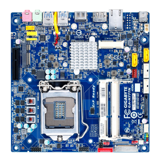
Page 8: Ga-H77Tn/Ga-B75Tn/Ga-H61Tn Motherboard Layout
GA-H77TN/GA-B75TN/GA-H61TN Motherboard Layout PCIEX4 SPKR EXT_CON MIC_IN LINE_OUT DMIC_CON CODEC USBX_2 iTE Super BIOS Socket 1155 USBX_1 BATTERY ® Intel H77 / HDMI B75 /H61 SO_DIMM1 SO_DIMM2 SYS_FAN SATA3 CLR_CMOS FUSB2_5 SATA0 SATA1 SATA2 SATA_PWR ATX_19V DC_IN SYS_PANEL CPU_FAN Only for GA-H77TN. -
Page 9: Chapter 1 Hardware Installation
Chapter 1 Hardware Installation Installation Precautions The motherboard contains numerous delicate electronic circuits and components which can become damaged as a result of electrostatic discharge (ESD). Prior to installation, carefully read the user's manual and follow these procedures: Prior to installation, make sure the chassis is suitable for the motherboard. Prior to installation, do not remove or break motherboard S/N (Serial Number) sticker or warranty sticker provided by your dealer. - Page 10 Dual channel memory architecture Support for DDR3 1600/1333/1066/800 MHz memory modules (Go to GIGABYTE's website for the latest supported memory speeds and memory modules.) Onboard Graphics Integrated Graphics Processor: - 1 x HDMI 1.3 port, supporting a maximum resolution of 1920x1200...
- Page 11 1 x DisplayPort Connectors 4 x USB 3.0/2.0 ports 4 x USB 2.0/1.1 ports1 x RJ-45 port 1 x DC-In power connector I/O Controller I/O Controller Chip ® Only for GA-H77TN. Only for GA-B75TN. Only for GA-H61TN. - 11 -...
- Page 12 Hardware Monitor System voltage detection CPU/System temperature detection CPU/System fan speed detection CPU fan speed control * For 4-pin CPU coolers only. * Whether the CPU fan speed control function is supported will depend on the CPU cooler you install. BIOS Use of licensed AMI EFI BIOS PnP 1.0a, DMI 2.0, SM BIOS 2.6, ACPI 2.0a...
-
Page 13: Installing The Cpu And Cpu Cooler
Read the following guidelines before you begin to install the memory: Make sure that the motherboard supports the memory. It is recommended that memory of the same capacity, brand, speed, and chips be used. (Go to GIGABYTE's website for the latest supported memory speeds and memory modules.) Make sure the motherboard supports the expansion card. -
Page 14: Back Panel Connectors
Back Panel Connectors DC Power Jack Connect the DC power to this port. RJ-45 LAN Port The Gigabit Ethernet LAN port provides Internet connection at up to 1 Gbps data rate. The following describes the states of the LAN port LEDs. Activity LED: Speed LED Activity LED... - Page 15 When removing the cable, pull it straight out from the connector. Do not rock it side to side to prevent an electrical short inside the cable connector. Only for GA-H77TN. Only for GA-B75TN. Only for GA-H61TN.
-
Page 16: Internal Connectors
Internal Connectors SYS_PANEL SYS_FAN SATA0 DMIC_CON SATA1 ATX_19V SATA2 MON_SW SATA3 BL_SW FUSB2_1 SPKR FUSB2_2 BATTERY FUSB2_3 CLR_CMOS FUSB2_5 LCD_VCC FP_AUDIO FPD_PWR DISPLAY_BRT WF_LED LVDS SATA_PWR CPU_FAN Read the following guidelines before connecting external devices: First make sure your devices are compliant with the connectors you wish to connect. Before installing the devices, be sure to turn off the devices and your computer. - Page 17 SATA0 (SATA 3Gb/s Connector) The SATA connectors conform to SATA 3Gb/s standard and are compatible with SATA 1.5Gb/s standard. Each SATA connector supports a single SATA device. Pin No. SATA0 Only for GA-H77TN. Only for GA-B75TN. Only for GA-H61TN. - 17 -...
- Page 18 4) SATA2 (SATA 3Gb/s Connector) The SATA connectors conform to SATA 3Gb/s standard and are compatible with SATA 1.5Gb/s standard. Each SATA connector supports a single SATA device. Pin No. SATA2 Only for GA-H77TN. Only for GA-B75TN. Only for GA-H61TN. - 18 -...
- Page 19 Each SATA connector supports a single SATA device. Pin No. SATA3 6) FUSB2_1 (USB 2.0/1.1 Header) optional USB bracket. For purchasing the optional USB bracket, please contact the local dealer. Pin No. USB3- USB2- USB3+ USB2+ No Pin Only for GA-H77TN. Only for GA-B75TN. - 19 -...
- Page 20 7/8/9) FUSB2_2/FUSB2_3/FUSB2_5 (USB 2.0/1.1 Headers) FUSB2_2/FUSB2_3 Pin No. USB- USB+ FUSB2_5 No Pin 10) FP_AUDIO (Front Panel Audio Header) ® The front panel audio header supports Intel connect your chassis front panel audio module to this header. Make sure the wire assignments of the module connector match the pin assignments of the motherboard header.
- Page 21 11) DISPLAY_BRT (Flat Panel Display Headers) The FPD is a high-speed interface connecting the output of a video controller in a laptop computer, computer monitor or LCD television set to the display panel. Most laptops, LCD computer monitors and LCD TVs use this interface internally. Pin No.
- Page 22 13/14) CPU_FAN/SYS_FAN (Fan Headers) All fan headers on this motherboard are 4-pin. Most fan headers possess a foolproof insertion design. When connecting a fan cable, be sure to connect it in the correct orientation (the black connector wire is the ground wire). The speed control function requires the use of a fan with fan speed control design. For optimum heat dissipation, it is recommended that a system fan be installed inside the chassis.
- Page 23 16) ATX_19V (2 Pin Power Connector) This power connector is for the integrated 19V chassis power supply. Pin No. +19V 17) MON_SW (Flat panel display switch header) This header allows you to connect an on/off switch for the display. Pin No. Mon_SW - 23 -...
- Page 24 18) BL_SW (Back Light Switch) Pin No. BL_DOWN BL_UP 19) SPKR (Speaker Header) This header connects to the speaker on the chassis front panel. The system reports system startup status by issuing a beep code. One single short beep will be heard if no problem is detected at system startup.
- Page 25 20) BATTERY (Battery cable connector) in the CMOS when the computer is turned off. Replace the battery when the battery voltage drops to a low level, or the CMOS values may not be accurate or may be lost. Pin No. RTC Reset Always turn off your computer and unplug the power cord before replacing the battery.
- Page 26 22) LCD_VCC (LVDS drive voltage Jumper) 1-2 Close: Set to 3V 2-3 Close: Set to 5V (Default setting) 23) FPD_PWR (Flat panel display power Jumper) 1-2 Close: Set to 12V 2-3 Close: Set to 19V (Default setting) - 26 -...
- Page 27 24) WF_LED (WIFI activity indicator LED Header) This header allows you to connect a WiFi operation indicator LED. Pin No. LED_WLAN 25) SATA_PWR (SATA Power Connector) This connector provides power to installed SATA devices. Connect the included SATA power cable to the SATA_PWR connector. Then connect the SATA/optical drive power connectors to your hard drive and optical drive.
-
Page 28: Chapter 2 Bios Setup
Chapter 2 BIOS Setup BIOS (Basic Input and Output System) records hardware parameters of the system in the CMOS on the saving system parameters and loading operating system, etc. BIOS includes a BIOS Setup program that the power is turned off, the battery on the motherboard supplies the necessary power to the CMOS to keep To access the BIOS Setup program, press the <F2>... - Page 29 Main This setup page includes all the items in standard compatible BIOS Advanced This setup page includes all the items of AMI BIOS special enhanced features. Chipset Boot Security restrict access to the system and BIOS Setup. A supervisor password allows you to make changes in BIOS Setup. A user password only allows you to view the BIOS settings but not to make changes.
-
Page 30: The Main Menu
Press <Esc> to exit the help screen. Help for each item is in the Item Help block on the right side of the submenu. (Sample BIOS Version: GA-H77TN F1) access more advanced options. When the system is not stable as usual, select the Restore Defaults item to set your system to its defaults. - Page 31 BIOS Information BIOS Vendor Display BIOS vendor information. Core Version Display version of the processor. Compliency Display compliency information. Project Version BIOS Build Date and Time Displays the date and time when the BIOS setup utility was created. MAC Address Displays the MAC address information.
-
Page 32: Advanced Menu
Advanced Menu Select a submenu item, then press Enter to access the related submenu screen. DDR over voltage Enable/Disable DDR over voltage. Options available: Enabled/Disabled. Default setting is Disabled. - 32 -... -
Page 33: Acpi Settings
2-2-1 ACPI Settings ACPI Sleep State Select the highest ACPI sleep state the system will enter, when the suspend button is pressed. Suspend Disabled/S1 only (CPU Stop Clock)/S3 only (Suspend to RAM). Default setting is S3 only (Suspend to RAM). - 33 -... - Page 34 CPU Type Displays the processor type information. CPU Signature Displays the processor ID information. Microcode Patch Display the information of the processor microcode patch. CPU Speed Display the information of the processor speed. Processor Cores Display the information of the processor core. Intel HT Technology Display Intel Hyper Threading Technology function support information.
- Page 35 L2 Cache Display the information of L2 Cache per Core. L3 Cache Display the information of total L3 Cache per socket. (Note) Execute Disable Bit When this item enabled, the processor prevents the execution of code in data-only memory pages. This Options available: Enabled/Disabled.
- Page 36 Hard drive information should be labeled on the outside device casing. Enter the appropriate option based on this information. Only for GA-H77TN. Only for GA-B75TN. Only for GA-H61TN. - 36 -...
-
Page 37: Intel(R) Rapid Start Technology
2-2-4 Intel (R) Rapid Start Technology (Note) Intel(R) Rapid Start Technology Enable/Disable the Intel Rapid Start Technology (IRSTe) funciton. The IRSTe enables your system to get up and running faster from even the deepest sleep, saving time and power consumption. Option available: Enabled/Disabled. -
Page 38: H/W Monitor
2-2-5 H/W Monitor Press Enter to view the Hardware Monitor screen which displays a real-time record of the CPU/system tem- CPU/System FAN Fail Detect Enable CPU/System Fan Stop Warning function. Option available: Enabled/Disabled. Default setting is Enabled. CPU/System SMART FAN Control Enable CPU/System Smart Fan function. -
Page 39: Intel(R) Smart Connect Technology
2-2-6 Intel(R) Smart Connect Technology Enables or disables Intel Smart Connect Technology. (Default: Disabled) - 39 -... -
Page 40: Network Stack
2-2-7 Network Stack Network stack Disables or enables booting from the network to install a GPT format OS, such as installing the OS from the Windows Deployment Services server. (Default: Disable Link) Ipv4 PXE Support Network stack is enabled. Ipv6 PXE Support is enabled. - Page 41 EIST (Enhanced Intel SpeedStep Technology) Conventional Intel SpeedStep Technology switches both voltage and frequency in tandem between high and low levels in response to processor load. Options available: Enabled/Disabled. Default setting is Enabled. Turbo Mode When this feature is enabled, the processor can dynamically overclock one or two of its four processing cores to improve performance with applications that are not multi-threaded or optimized for quad-core processors.
-
Page 42: Realtek Pcie Gbe Family Controller
2-2-9 Realtek PCIe GBE Family Controller - 42 -... -
Page 43: Chipset Menu
Chipset Menu Azalia Enable/Disable onboard audio controller. Options available: Auto/Enabled/Disabled. Default setting is Enabled. Verb Table Options available: Mode A/Mode B. Default setting is Mode A. Onboard LAN Enable/Disable onboard LAN controller. Options available: Enabled/Disabled. Default setting is Enabled. ERP Support Enable/Disable Erp support function. -
Page 44: Boot Menu
Boot Menu The Boot menu allows you to set the drive priority during system boot-up. BIOS setup will display an error Bootup NumLock State Allows you to select power-on state for NumLock function. Options available: On/Off. Default setting is On. Fast Boot If enabled, the system will speed the boot up time. - Page 45 CSM parameters Launch CSM Enables or disables UEFI CSM (Compatibility Support Module) to support a legacy PC boot process. Enabled Enables UEFI CSM. (Default) Disabled Disables UEFI CSM and supports UEFI BIOS boot process only. Allows you to select which type of operating system to boot. UEFI and Legacy Allows booting from operating systems that support legacy option ROM or UEFI op- tion ROM.
- Page 46 Launch Video OpROM policy Allows you to select whether to enable the UEFI or legacy option ROM for the video controller. Do not launch Disables option ROM. Legacy only Enables legacy option ROM only. (Default) UEFI only Enables UEFI option ROM only. Launch CSM is set to Enabled.
-
Page 47: Security Menu
Security Menu The Security menu allows you to safeguard and protect the system from unauthorized use by setting up ac- cess passwords. There are two types of passwords that you can set: Adminstrator Password Entering this password will allow the user to access and change all settings in the Setup Utility. User Password Entering this password will restrict a user’s access to the Setup menus. - Page 48 Secure Boot Mode Option available: Standard/Custom. Default setting is Standard. - 48 -...
-
Page 49: Exit Menu
Exit Menu The Exit menu displays the various options to quit from the BIOS setup. Highlight any of the exit options then press Enter. Save Changes and Exit Saves changes made and close the BIOS setup and exit system setup. Options available: Yes/No. - Page 50 Save as User Defaults Press <Enter> on this item and then press the <Y> key to save as user default settings. Options available: Yes/No. Restore User Defaults Press <Enter> on this item and then press the <Y> key to restore user default settings. Options available: Yes/No.
-
Page 51: Chapter 3 Appendix
Appendix Troubleshooting 3-1-1 Frequently Asked Questions To read more FAQs for your motherboard, please go to the Support & Downloads\FAQ page on GIGABYTE's website. Q: Why is the light of my keyboard/optical mouse still on after the computer shuts down? A: Some motherboards provide a small amount of standby power after the computer shuts down and that's why the light is still on. -
Page 52: Troubleshooting Procedure
3-1-2 Troubleshooting Procedure If you encounter any troubles during system startup, follow the troubleshooting procedure below to solve the problem. START Turn off the power. Remove all peripherals, connecting cables, and power cord etc. Make sure the motherboard does not short-circuit with the chassis or Isolate the short circuit. - Page 53 The power supply, CPU or When the computer is turned on, is the CPU cooler running? CPU socket might fail. The graphics card, expansion slot, or monitor Check if there is display on your monitor. might fail. Turn off the computer. Plug in the keyboard and mouse and restart the computer.
-
Page 54: Regulatory Statements
GIGABYTE provides the following information on how you can responsibly recycle or reuse Restriction of Hazardous Substances (RoHS) Directive Statement GIGABYTE products have not intended to add and safe from hazardous substances (Cd, Pb, Hg, Cr+6, PBDE and PBB). The parts and components have been carefully selected to meet RoHS requirement. Moreover, we at GIGABYTE are continuing our efforts to develop products that do not use internationally banned toxic chemicals. -
Page 55: Contact Us
Shenyang Giga-Byte SINGAPORE PTE. LTD. - Singapore TEL: +86-24-83992342 WEB address : http://www.gigabyte.sg FAX: +86-24-83992102 Thailand GIGABYTE TECHNOLOGY (INDIA) LIMITED - India WEB address : http://th.giga-byte.com WEB address : http://www.gigabyte.in Vietnam Saudi Arabia WEB address : http://www.gigabyte.vn WEB address : http://www.gigabyte.com.sa Gigabyte Technology Pty. - Page 56 WEB address : http://www.gigabyte.com.gr WEB address : http://www.gigabyte.kz Czech Republic You may go to the GIGABYTE website, select your language WEB address : http://www.gigabyte.cz in the language list on the top right corner of the website. GIGABYTE Global Service System...