Table of Contents
Advertisement
Advertisement
Table of Contents

Related Manuals for Gigabyte B450M GAMING


Summary of Contents for Gigabyte B450M GAMING
- Page 1 B450M GAMING User's Manual Rev. 1001 For more product details, please visit GIGABYTE's website. To reduce the impacts on global warming, the packaging materials of this product are recyclable and reusable. GIGABYTE works with you to protect the environment.
- Page 2 The trademarks mentioned in this manual are legally registered to their respective owners. Disclaimer Information in this manual is protected by copyright laws and is the property of GIGABYTE. No part of this manual may be reproduced, copied, translated, transmitted, or published in any form or by any means without GIGABYTE's prior written permission.
-
Page 3: Table Of Contents
Table of Contents B450M GAMING Motherboard Layout ................4 Chapter 1 Hardware Installation ..................5 Installation Precautions ..................5 ..................6 Installing the CPU .................... 9 Installing the Memory ..................9 Installing an Expansion Card ................. 10 Back Panel Connectors .................. 10 Internal Connectors .................. -
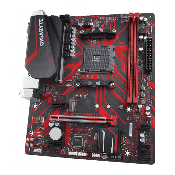
Page 4: B450M Gaming Motherboard Layout
B450M GAMING Motherboard Layout CPU_FAN KB_MS ATX_12V Socket AM4 SYS_FAN1 USB_LAN M_BIOS PCIEX1_1 M2A_SOCKET B450M GAMING PCIEX16 ® GbE LAN SATA3 SATA3 B450 ® Super I/O PCIEX1_2 F_USB2 F_USB30 SYS_FAN2 COMA F_USB1 F_PANEL Box Contents B450M GAMING motherboard Two SATA cables... -
Page 5: Chapter 1 Hardware Installation
Chapter 1 Hardware Installation Installation Precautions The motherboard contains numerous delicate electronic circuits and components which can become manual and follow these procedures: Prior to installation, make sure the chassis is suitable for the motherboard. warranty sticker provided by your dealer. These stickers are required for warranty validation. Always remove the AC power by unplugging the power cord from the power outlet before installing or removing the motherboard or other hardware components. - Page 6 2nd Generation processors ™ ™ Vega Graphics processors ™ 1st Generation processors Chipset Memory (Go to GIGABYTE's website for the latest supported memory speeds and memory Onboard Integrated Graphics Processor: Graphics Maximum shared memory of 2 GB Audio ® ALC887 codec 2/4/5.1/7.1-channel...
- Page 7 Internal 1 x 24-pin ATX main power connector 1 x 8-pin ATX 12V power connector Connectors 1 x CPU fan header 2 x system fan headers 1 x M.2 Socket 3 connector 4 x SATA 6Gb/s connectors 1 x front panel header 1 x front panel audio header 1 x USB 3.1 Gen 1 header 2 x USB 2.0/1.1 headers...
- Page 8 Form Factor Micro ATX Form Factor; 24.4cm x 20.5cm prior notice. Please visit GIGABYTE's website Please visit the Support\Utility List for support lists of CPU, memory page on GIGABYTE's website to download the latest version of apps. - 8 -...
-
Page 9: Installing The Cpu
Installing the CPU Make sure that the motherboard supports the CPU. (Go to GIGABYTE's website for the latest Always turn off the computer and unplug the power cord from the power outlet before installing the CPU to prevent hardware damage. -
Page 10: Installing An Expansion Card
Installing an Expansion Card Make sure the motherboard supports the expansion card. Carefully read the manual that came with your expansion card. Always turn off the computer and unplug the power cord from the power outlet before installing an expansion card to prevent hardware damage. Back Panel Connectors PS/2 Keyboard and PS/2 Mouse Port D-Sub Port... - Page 11 RJ-45 LAN Port The Gigabit Ethernet LAN port provides Internet connection at up to 1 Gbps data rate. The following Connection/ State State Orange 1 Gbps data rate Blinking Green 100 Mbps data rate No data transmission or receiving is occurring LAN Port 10 Mbps data rate USB 2.0/1.1 Port...
-
Page 12: Internal Connectors
Internal Connectors ATX_12V SPEAKER F_USB30 CPU_FAN F_USB1/F_USB2 SYS_FAN1/2 SATA3 0/1/2/3 COMA M2A_SOCKET SPDIF_O CLR_CMOS F_PANEL LED_CPU F_AUDIO First make sure your devices are compliant with the connectors you wish to connect. Before installing the devices, be sure to turn off the devices and your computer. Unplug the power cord from the power outlet to prevent damage to the devices. - Page 13 1/2) ATX_12V/ATX (2x4 12V Power Connector and 2x12 Main Power Connector) With the use of the power connector, the power supply can supply enough stable power to all the components off and all devices are properly installed. The power connector possesses a foolproof design. Connect the power supply cable to the power connector in the correct orientation.
- Page 14 3/4) CPU_FAN/SYS_FAN1/2 (Fan Headers) All fan headers on this motherboard are 4-pin. Most fan headers possess a foolproof insertion design. When connecting a fan cable, be sure to connect it in the correct orientation (the black connector wire fan with fan speed control design. For optimum heat dissipation, it is recommended that a system fan be installed inside the chassis.
- Page 15 6) M2A_SOCKET (M.2 Socket 3 Connector) Step 1: Use a screw driver to unfasten the screw and standoff from the motherboard. Locate the proper mounting Step 2: Step 3: 7) SPDIF_O (S/PDIF Out Header) Pin No. No Pin ™ processor. - 15 -...
- Page 16 8) F_PANEL (Front Panel Header) Connect the power switch, reset switch, and system status indicator on the chassis to this header according to the pin assignments below. Note the positive and negative pins before connecting the cables. PLED Power Switch Connects to the power status indicator on the System Status S3/S4/S5...
- Page 17 10) SPEAKER (Speaker Header) Connects to the speaker on the chassis front panel. The system reports system startup status by issuing a beep code. One single short beep will be heard if no problem is detected at system startup. Pin No. SPK- 11) F_USB30 (USB 3.1 Gen 1 Header) dealer.
- Page 18 13) TPM (Trusted Platform Module Header) Pin No. Pin No. VCC3 No Pin LCLK 14) COMA (Serial Port Header) The COM header can provide one serial port via an optional COM port cable. For purchasing the optional COM port cable, please contact the local dealer. Pin No.
- Page 19 16) CLR_CMOS (Clear CMOS Jumper) the CMOS values, use a metal object like a screwdriver to touch the two pins for a few seconds. Open: Normal Short: Clear CMOS Values Always turn off your computer and unplug the power cord from the power outlet before clearing the CMOS values.
-
Page 20: Chapter 2 Bios Setup
Chapter 2 BIOS Setup saving system parameters and loading operating system, etc. BIOS includes a BIOS Setup program that allows When the power is turned off, the battery on the motherboard supplies the necessary power to the CMOS to Q-Flash allows the user to quickly and easily upgrade or back up BIOS without entering the operating system. and updates the BIOS. -
Page 21: The Main Menu
The Main Menu System Time Setup Menus Hardware Information Current Settings Quick Access Bar allows you to enter Easy Mode, select Q-Flash. Classic Setup Function Keys < Move the selection bar to select a setup menu < Execute command or enter a menu <... - Page 22 M.I.T. Whether the system will work stably with the overclock/overvoltage settings you made is dependent on your overall and reduce the useful life of these components. This page is for advanced users only and we recommend you not to alter the default settings to prevent system instability or other unexpected results. (Inadequately altering the settings Advanced Frequency Settings Host Clock Value (Note)
- Page 23 Core Performance Boost AMD Cool&Quiet function SVM Mode Global C-state Control Allows you to determine whether to let the CPU enter C states. When enabled, the CPU core frequency Power Supply Idle Control Enables or disables Package C6 State. Low Current Idle Enables this function.
- Page 24 Advanced Memory Settings (Note) , System Memory Multiplier, Memory Frequency(Mhz) The settings above are synchronous to those under the same items on the Advanced Frequency Settings menu. Memory Timing Mode Manual and Options are: Auto When using a non-XMP memory module or is set to Disabled, the value is set to Standard Timing Control, Advanced Timing Control, CAD Bus Setup Timing, CAD Bus...
- Page 25 Smart Fan 5 Settings Monitor Fan Speed Control Allows you to determine whether to enable the fan speed control function and adjust the fan speed. Normal Allows the fan to run at different speeds according to the temperature. You can adjust the fan speed with System Information Viewer based on your system requirements.
-
Page 26: System
System This section provides information on your motherboard model and BIOS version. You can also select the default language used by the BIOS and manually set the system time. System Language Selects the default language used by the BIOS. System Date value. -
Page 27: Bios
A password is only required for entering the BIOS Setup program. System A password is required for booting the system and for entering the BIOS Setup Full Screen LOGO Show Allows you to determine whether to display the GIGABYTE Logo at system startup. Disabled skips the - 27 -... - Page 28 Fast Boot Enables or disables Fast Boot to shorten the OS boot process. Ultra Fast provides the fastest bootup SATA Support Fast Boot is set to Enabled or Ultra Fast. VGA Support Allows you to select which type of operating system to boot. Fast Boot is set to Enabled or Ultra Fast.
- Page 29 Other PCI Device ROM Priority than the LAN, storage device, and graphics controllers. CSM Support is set to Enabled. Network Stack Ipv4 PXE Support Network Stack is enabled. Ipv4 HTTP Support Network Stack is enabled. Ipv6 PXE Support Network Stack is enabled. Ipv6 HTTP Support Network Stack is enabled.
-
Page 30: Peripherals
Peripherals AMD CPU fTPM Initial Display Output graphics. Legacy USB Support XHCI Hand-off EHCI Hand-off Port 60/64 Emulation Enables or disables emulation of I/O ports 64h and 60h. This should be enabled for full legacy support USB Mass Storage Driver Support Mass Storage Devices is installed. - Page 31 RGB Fusion (Onboard LED) RGB Fusion (LED strip) HD Audio Controller If you wish to install a 3rd party add-in audio card instead of using the onboard audio, set this item to Disabled. Above 4G Decoding Enables or disables 64-bit capable devices to be decoded in above 4 GB address space (only if your system Enabled if more than one advanced graphics card are installed and their drivers are not able to be launched when entering the operating system (because of the limited 4 GB Trusted Computing...
-
Page 32: Chipset
Chipset IOMMU (Note) Integrated Graphics Enables or disables the onboard graphics function. Auto The BIOS will automatically enable or disable the onboard graphics depending on the Forces Enables the onboard graphics. UMA Mode (Note) Specify the UMA mode. Auto UMA Auto Sets the display resolution. - Page 33 SATA Mode mode. NVMe RAID mode (M2A_SOCKET Connector) APU SATA Port Enable (M2A_SOCKET Connector) Chipset SATA Port Enable (SATA3 0, 1, 2, 3 Connectors) APU SATA Port 0 (M2A_SOCKET Connector) Chipset SATA Port 0/1/2/3 (SATA3 0, 1, 2, 3 Connectors) - 33 -...
-
Page 34: Power
Power AC BACK Memory The system returns to its last known awake state upon the return of the AC power. Always On The system is turned on upon the return of the AC power. Power On By Keyboard Allows the system to be turned on by a PS/2 keyboard wake-up event. Note: To use this function, you need an ATX power supply providing at least 1A on the +5VSB lead. - Page 35 is set to Enabled and power on by keyboard. Soft-Off by PWR-BTTN button is pressed for less than 4 seconds, the system will enter suspend mode. Power Loading Enables or disables dummy load. When the power supply is at low load, a self-protection will activate causing it to shutdown or fail.
-
Page 36: Save & Exit
Save & Exit Save & Exit Setup Yes. This saves the changes to the CMOS and exits the BIOS Setup program. Select No Exit Without Saving Yes. This exits the BIOS Setup without saving the changes made in BIOS Setup to the CMOS. Select No Load Optimized Defaults Yes to load the optimal BIOS default settings. -
Page 37: Chapter 3 Appendix
Chapter 3 Appendix RAID Levels RAID 0 RAID 1 RAID 10 Minimum Number of Array Capacity Number of hard drives * Fault Tolerance Before you begin, please prepare the following items: Windows setup disk. Motherboard driver disk. A USB thumb drive. A. - Page 38 4. On the Select Physical Disks to Enabled. Next, use the down arrow key to move to Apply Changes the previous screen and set the Array Size, Array Size Unit, Read Cache Policy and Write Cache Policy. 5. After setting the capacity, move to Create Array 6.
- Page 39 After installing the operating system, insert the motherboard driver disk into your optical drive. Click install. You can click the Xpress Install the arrow icon to individually install the drivers you need. Please visit GIGABYTE's website for Please visit GIGABYTE's website for more troubleshooting information. more software information.
- Page 40 Contravention will be prosecuted. We believe that the information contained herein was accurate in all respects at the time of printing. GIGABYTE cannot, however, assume any responsibility for errors or omissions in this text. Also note that the information in this document is subject to change without notice and should not be construed as a commitment by GIGABYTE.
- Page 41 FCC Notice (U.S.A. Only) This equipment has been tested and found to comply with the limits for a Class B digital device, pursuant to Part in a residential installation. This equipment generates, uses, and can radiate radio frequency energy and, if not installed and used in accordance with the instructions, may cause harmful interference to radio communications.
-
Page 42: Contact Us
Contact Us GIGA-BYTE TECHNOLOGY CO., LTD. TEL: +886-2-8912-4000, FAX: +886-2-8912-4005 GIGABYTE eSupport https://esupport.gigabyte.com - 42 -...