Table of Contents
Advertisement
Quick Links
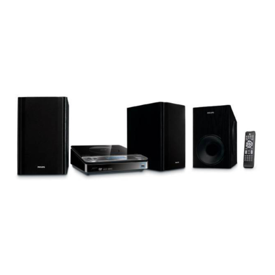
DVD Micro Theater
CONTENTS
Technical specification ..................................................................1-2
Version variation... ........................................................................1-2
Service measurement setup..........................................................1-3
Service aids .................................................................................1-4
Instructions on CD playability ...............................................2-1.. 2-2
Disassembly diagram............ ........................................................3-1
Block diagram ................................................................................4-1
Wiring diagram ..............................................................................4-2
Main board
Circuit diagram ..................................................................5-1..5-2
Layout diagram ..................................................................5-3..5-4
Display board
Circuit diagram .........................................................................6-1
Layout diagram .........................................................................6-2
AMP board (in subwoofer box)
Circuit diagram .........................................................................7-1
Layout diagram .........................................................................7-2
Exploded view diagram .................................................................8-1
Mechanical parts list ......................................................................8-2
Electrical parts list...................................................................9-1..9-3
©
Copyright 2008 Philips Consumer Electronics B.V. Eindhoven, The Netherlands
All rights reserved. No part of this publication may be reproduced, stored in a retrieval
system or transmitted, in any form or by any means, electronic, mechanical, photocopying,
or otherwise without the prior permission of Philips.
Published by LX 0824 Service Audio
Version 1.1
All manuals and user guides at all-guides.com
Subject to modification
MCD179
-/12/58
3141 785 32551
Advertisement
Table of Contents

Related Manuals for Philips MCD179/12/58


Summary of Contents for Philips MCD179/12/58
-
Page 1: Table Of Contents
Electrical parts list..............9-1..9-3 © Copyright 2008 Philips Consumer Electronics B.V. Eindhoven, The Netherlands All rights reserved. No part of this publication may be reproduced, stored in a retrieval system or transmitted, in any form or by any means, electronic, mechanical, photocopying, or otherwise without the prior permission of Philips. -
Page 2: Technical Specification
All manuals and user guides at all-guides.com 1 - 2 TECHNICAL SPECIFICATION AMPLIFIER Main unit Output power Power Supply Rating ....220 -240V / 50 Hz L/R speakers ......25 W /channel RMS Power Consumption Subwoofer ............. 50 W RMS Active ................ - Page 3 All manuals and user guides at all-guides.com MEASUREMENT SETUP Tuner FM Bandpass LF Voltmeter 250Hz-15kHz e.g. PM2534 e.g. 7122 707 48001 RF Generator e.g. PM5326 S/N and distortion meter e.g. Sound Technology ST1700B Use a bandpass filter to eliminate hum (50Hz, 100Hz) and disturbance from the pilottone (19kHz, 38kHz). Tuner AM (MW,LW) Bandpass LF Voltmeter...
-
Page 4: Service Aids
All manuals and user guides at all-guides.com SERVICE AIDS WARNING All ICs and many other semi-conductors are susceptible to electrostatic discharges (ESD). Careless handling during repair can reduce life drastically. When repairing, make sure that you are connected with the same potential as the mass of the set via a wrist wrap with resistance. -
Page 5: Instructions On Cd Playability
All manuals and user guides at all-guides.com 2 - 1 INSTRUCTIONS ON CD PLAYABILITY Customer complaint "CD related problem" Set remains closed! check playability playability ok ? For flap loaders (= access to CD drive possible) "fast" lens cleaning cleaning method is recommended check playability playability... - Page 6 All manuals and user guides at all-guides.com 2 - 2 INSTRUCTIONS ON CD PLAYABILITY PLAYABILITY CHECK LIQUID LENS CLEANING Before touching the lens it is advised to clean the surface of the lens by blowing clean air over it. For sets which are compatible with CD-RW discs This to avoid that little particles make scratches on use CD-RW Printed Audio Disc ....7104 099 96611 the lens.
-
Page 7: Disassembly Diagram
All manuals and user guides at all-guides.com 3 - 1 DISASSEMBLY DIAGRAM... -
Page 8: Block Diagram
All manuals and user guides at all-guides.com 4 - 1 4 - 1 SET BLOCK DIAGRAM... -
Page 9: Wiring Diagram
All manuals and user guides at all-guides.com 4 - 2 4- 2 SET WIRING DIAGRAM... -
Page 10: Circuit Diagram
All manuals and user guides at all-guides.com 5 - 1 5 - 1 CIRCUIT DIAGRAM - MAIN BOARD AV-OUT PART... -
Page 11: Circuit Diagram
All manuals and user guides at all-guides.com 5 - 2 5 - 2 CIRCUIT DIAGRAM - MAIN BOARD DVD PART... - Page 12 All manuals and user guides at all-guides.com 5 - 3 5 - 3 LAYOUT DIAGARM - MAIN BOARD COMPONENT SIDE VIEW...
- Page 13 All manuals and user guides at all-guides.com 5 - 4 5 - 4 LAYOUT DIAGARM - MAIN BOARD COPPER SIDE VIEW...
- Page 14 All manuals and user guides at all-guides.com 6 - 1 6 - 1 CIRCUIT DIAGRAM - DISPLAY BOARD...
- Page 15 All manuals and user guides at all-guides.com 6 - 2 6 - 2 LAYOUT DIAGARM - DISPLAY BOARD...
- Page 16 All manuals and user guides at all-guides.com 7 - 1 7 - 1 CIRCUIT DIAGRAM - AMP BOARD in subwoofer box AMP is not repaired,diagram for referrence only.
- Page 17 All manuals and user guides at all-guides.com 7 - 2 7 - 2 LAYOUT DIAGRAM - AMP BOARD in subwoofer box AMP is not repaired,diagram for referrence only.
-
Page 18: Exploded View Diagram
All manuals and user guides at all-guides.com 8 - 1 8 - 1 EXPLODED VIEW DIAGRAM S001 123#... -
Page 19: Mechanical Partslist
All manuals and user guides at all-guides.com 8 - 2 MECHANICAL PARTSLIST 996510012051 TUNER PCB ASSY(-/12) 996510012777 TUNER PCB ASSY(-/58) 996510019958 BOTTOM CABINET 996510012057 TOP CAB FRONT 996510019965 HOUSING 996510012096 DVD HOLDER 996510012059 USB BRACKET 996510012061 CD DOOR 996510008685 DAMPER GEAR ASSY (70kgf/cm) 996510012062 TWO KEYS 996510012063... -
Page 20: Electrical Partslist
All manuals and user guides at all-guides.com 9 - 1 ELECTRICAL PARTSLIST MAIN BOARD ASSEMBLY D001 996500042437 CH-DIODE SS14 SMA/DO-214AC D003 996500042437 CH-DIODE SS14 SMA/DO-214AC D201 996510000323 SMD DIODE BAS316 D202 996510000323 SMD DIODE BAS316 D203 996510000323 SMD DIODE BAS316 D204 996510000323 SMD DIODE BAS316... - Page 21 All manuals and user guides at all-guides.com 9 - 2 ELECTRICAL PARTSLIST MAIN BOARD ASSEMBLY U004 996510012078 IC LM1117F-3.3V SOT-89 U005 996510012080 IC MC34063A SOP8 U101 996510019966 IC GY399R LQFP44-1010 U102 996510012074 RESET IC AT24C01B U201 996510009444 IC MT1389FE/USB CMTK TQFP-256 U202 996510012078 IC LM1117F-3.3V SOT-89...
- Page 22 All manuals and user guides at all-guides.com 9 - 3 ELECTRICAL PARTSLIST DISPLAY/KEY BOARD ASSEMBLY D401 996510012043 LCD DISPLAY D402 996500042438 LED LAMP 2x5x7mm (WHITE) D403 996500042438 LED LAMP 2x5x7mm (WHITE) D404 996500042438 LED LAMP 2x5x7mm (WHITE) D405 996500042438 LED LAMP 2x5x7mm (WHITE) D407 994000001234 LED LAMP 3MM (RED)