Chromalox CXH-A/B-03S Installation, Operation And Maintenance Instructions
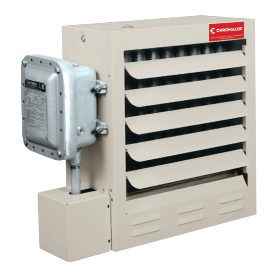
Hazardous location forced-air heater
Hide thumbs
Also See for CXH-A/B-03S:

Related Manuals for Chromalox CXH-A/B-03S


Summary of Contents for Chromalox CXH-A/B-03S
- Page 1 Installation, Operation and Maintenance Instructions CXH-A/B Hazardous Location Forced-Air Heater PF490CE-4 161-302421-007 March 2022...
-
Page 2: Table Of Contents
Table of Contents 1. Introduction .......................... 3 2. Safety ............................ 3 3. Specifications and Product Identification ................. 4 4. Mechanical Installation ....................... 6 5. Electrical Installation ......................8 6. Operation ........................... 11 7. Preventative Maintenance and Repair ................13 8. Repair and Replacement ....................14 9. -
Page 3: Introduction
1. Introduction This document contains safety, installation, operation, maintenance, and troubleshooting information for model CXH-A/B unit heaters. Always check www.chromalox.com to ensure you have the latest revision of this document. Revision date is listed on the cover page. 2. Safety... -
Page 4: Specifications And Product Identification
Wt. Kg. Model Voltage and Phase (ft.) BTUH /hr) (Lbs.) 380/400/415V 3ph 50Hz 485.8 606.4 533.4 88.9 346.1 CXH-A/B-03S 208/240V-1 or 3ph 60Hz 28 (8.5) 10,236 58 (127) (1189) (19-1/8) (23-7/8) (21) (3-1/2) (13-5/8) 480/575V 3ph 60Hz 380/400/415V 3ph 50Hz 485.8... - Page 5 Table C - Specifications Ex II 2 G Ex db IIB T3 Gb ATEX -40°C≤ T ≤ +40°C (-40°F ≤ T ≤ +104°F) Ex d 118 T3 Gb IECEx Standard CXH-A/B Models -40°C ≤ T ≤ +40°C (-40°F ≤ T ≤...
-
Page 6: Mechanical Installation
7. For proper mounting support, it is recommended that a maintained to adjacent walls and ceiling. If floor heat is Chromalox supplied wall, ceiling, or pole mounting kit be desired, do not mount higher than 8 to 10 feet (2.4 to 3.0 utilized. - Page 7 102mm Min. (4") Thds. For 2" Mounting 204mm Min. (8") Figure 3 – Installation Clearances Dimensions Heater Model In. (mm) CXH-A/B-03S to CXH-A/B-10S 17-5/8 (447.7) CXH-A/B-10M to CXH-A/B-20M 21-5/8 (533.4) 25-5/8 (635) CXH-A/B-25L to CXH-A/B-35L Figure 4 – Mounting Holes...
-
Page 8: Electrical Installation
5. Electrical Installation Prior to Installation 1. Follow all safety guidelines in this manual when perform- 6. 1”NPT Entry on top is factory equipped with a non-certi- ing electrical wiring. Electrical installation should be con- fied conduit plug ducted by qualified personnel. 7. - Page 9 Diagram 1...
- Page 10 Table D – Electrical Ratings Minimum Supply Wire Max. Fuse/ Total Current Circuit (AWG) Breaker size Model Volts Phase (Amps) Amps (90˚C Ambient) (Amps) Wiring Diagram CXH-A/B-03 10.0 CXH-A/B-05 12.8 16.0 CXH-A/B-07 17.6 22.0 CXH-A/B-10 24.8 31.0 CXH-A/B-15 36.9 46.2 CXH-A/B-03 CXH-A/B-05 CXH-A/B-07...
-
Page 11: Operation
6. Operation General 3. Unit should not be operated with louvers fully closed. 1. The CXH-A/B unit heaters use a sealed water-glycol filled Mechanical stops are incorporated into the design of the heat exchanger. The electric immersion elements trans- cabinet to limit the degree of closure. Do not force the fer heat energy directly to the fluid generating a fluid/va- louvers beyond these stops. - Page 12 Optional Integral Thermostat 1. Do not tamper with or remove thermostat terminal cover. Thermostat may only be serviced by Chromalox person- nel. 2. Thermostats have a set range from 50-90°F (10-32°C). 3. To set the thermostat rotate dial to desired temperature.
-
Page 13: Preventative Maintenance And Repair
5. If during inspection, damage to threaded entries and/or flame paths is located, do not repair. Take unit out of 2. Maintenance and repairs should be performed by quali- service immediately and contact Chromalox to schedule fied personnel only. service. -
Page 14: Repair And Replacement
8. Repair and Replacement Replacing the Heat Exchanger Depending on model, heat exchanger weighs between 50 - 100lbs (approx. 25-50kg) and must be properly supported from bottom during removal. 1. Remove front case panel by removing 5 screws located on perimeter of case. 2. - Page 15 Replacing Motor and/or Fan Blade B. Loosen the four screws on the cabinet back holding 1. Disconnect the unit from power supply. the fan guard in place. 2. (Units with motor splice box) Remove 4 bolts and cover C. Pull the motor to the rear extending the conduit con- of motor splice box nection at the electrical enclosure.
- Page 16 If joints or flame paths appear to be damaged contact repaired. If flameproof joints appear to be damaged, con- Chromalox immediately for replacement. tact Chromalox immediately for motor replacement. 2. If threaded cover bolts or screws are damaged, they 2. The anti-condensationn heater can be activated only must only be replaced with factory provided fasteners.
- Page 17 Panel wrapper Washer lock Panel Bottom Hex Nut 3/8-16 Panel Front Plug conduit 1/2” Mounting Kit Adapter Louver Plug conduit 1” CXH-A/B-03S through 10S 027-302361-001 Washer Shoulder Union conduit 3/4” CXH-A/B-15M through 20M 027-302361-002 Spring Union conduit 3/4” Terminal Box Cover...
-
Page 18: Troubleshooting
Check for burn marks on the contactor terminals and (turning on/off rapidly) tions / short in wiring look for frayed or loose wires. Replace contactor. Limited Warranty: Please refer to the Chromalox limited warranty applicable to this product at http://www.chromalox.com/customer-service/policies/termsofsale.aspx. Chromalox 103 Gamma Drive Pittsburgh, PA 15238 (412) 967-3800 www.chromalox.com...