Nortel DMS-100 Series Installation, Operation And Maintenance Manual
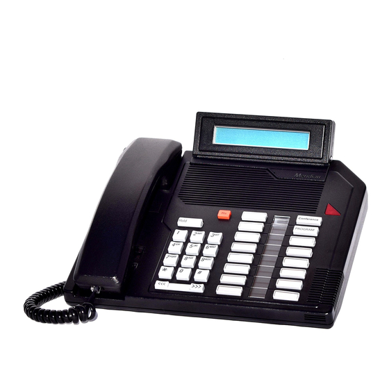
Meridian business set
Hide thumbs
Also See for DMS-100 Series:
- Replacement procedures (1100 pages) ,
- Maintenance manual (762 pages) ,
- Manual (543 pages)

Related Manuals for Nortel DMS-100 Series


Summary of Contents for Nortel DMS-100 Series
- Page 1 297-2011-214 DMS-100 Family M5316 Meridian Business Set Description, Installation, Operation, and Maintenance Manual Release 02.01 Standard February 1999...
- Page 2 The following are trademarks of Northern Telecom: Nortel, the Nortel globemark, DMS-100, Meridian.
-
Page 3: Publication History
Publication history October 1996 Release 01.01. Standard version for NA004 and up. February 1999 Release 02.01. Standard version changed from NA004 and up to CCM04 and 297–2011–214 02.01 Standard February 1999... - Page 4 Publication history 297–2011–214 02.01 Standard February 1999...
-
Page 5: Table Of Contents
Contents Publication history Chapter 1: Introduction General description 1-1 Physical characteristics 1-2 Other documentation 1-2 Chapter 2: Specifications Environmental and safety considerations 2-1 Temperature 2-1 Relative humidity 2-1 Electromagnetic interference 2-1 Atmospheric pollution 2-1 Vibration 2-2 Shock 2-2 Line engineering 2-2 Loop power 2-2 External power 2-2 Chapter 3: Operations and features... - Page 6 vi Contents Chapter 4: Installation Installing the M5316 4-1 Wall mounting the M5316 4-4 Chapter 5: Verification procedures Verification test routines 5-1 Maintenance 5-1 Loop check 5-1 Polarity check 5-2 Station Ringer test 5-3 Chapter 6: Replacement parts Figures Figure 3-1 M5316 keys and other components 3-3 Figure 3-2 M5316 key assignments 3-9...
-
Page 7: Chapter 1: Introduction
Chapter 1 Introduction General description The M5316 Meridian Business Set is designed for direct connection (through a non-loaded subscriber loop pair) to the Northern Telecom DMS–10, DMS–100, DMS–250, or Meridian SL–100 Digital Switching systems. The M5316 is partially loop powered and requires the use of a 16 V AC external power supply. -
Page 8: Physical Characteristics
1-2 Introduction Physical characteristics Figure 3-1 shows the main components of the M5316. The M5316 comes in three different colours: • Chameleon-grey (Engineering code NT4X42AA) • BTS light-grey (Engineering code NT4X42BA) • Black (Engineering code NT4X42CA) The Mean Time Between Failure (MTBF) for the M5316 is at least 100 years. -
Page 9: Chapter 2: Specifications
Chapter 2 Specifications The following specifications govern the performance of the M5316 Business Set and the environmental conditions under which this performance is achieved. Environmental and safety considerations The M5316 meets the Canadian and U.S. mandatory interconnect requirements for Telephone Equipment, CSA, DOC, UL, FCC (part 15 & part 68). -
Page 10: Vibration
2-2 Specifications Vibration The M5316 is designed to work to specifications after being subjected to the following vibrations in each of three orthogonal directions for 90 minutes: • Vibration frequency of 5 Hz to 500 Hz • Maximum half displacement 0.35mm (0.014 in) •... - Page 11 Specifications 2-3 297–2011–214 02.01 Standard February 1999...
-
Page 12: Chapter 3: Operations And Features
Chapter 3 Operations and features Basic operations The M5316 Meridian Business Set can be used to make voice calls and operate selected DMS–10, DMS–100, or Meridian SL–100 features. All supported features can be accessed using keys provided on the M5316. For further details about software requirements, refer to NTP 297–2011–100 and NTP 297–1001–310 respectively. -
Page 13: Alphanumeric Display
3-2 Operations and features Alphanumeric display The M5316 display screen allows access to the following features: Called Number Display/Called Name Display The display of the called number (or name of the party being called, when available) is always activated as dialing takes place. Calling Number Display/Calling Name Display The calling number (or name of the calling party, when available) for calls originating within the same switch is displayed when the first ringing tone... -
Page 14: Description Of Features
Operations and features 3-3 Description of features The M5316 Business Set (see Figure 3-1) is characterized by the following: • there are 15 fixed keys with no LCD indicators: Release key (1), Hold Key (1), Volume key (1), dial pad keys (12) •... - Page 15 3-4 Operations and features Table 3-1 Summary of M5316 keys and indicators Key or indicator Description Speaker Monitors the progress of a call without lifting the handset. Handset Used for talking on the phone—automatically selects the prime directory number when lifted. Display Shows call and installation information.
-
Page 16: Basic Features
Operations and features 3-5 Basic features Every Business Set has the basic features described below. Automatic Prime Directory Number (PDN) selection Allows the user to select the prime DN (i.e. the DN assigned to the first feature/line key) by going off-hook to answer a call without pressing a DN key. -
Page 17: Features Operation
3-6 Operations and features Features operation The fixed keys on the M5316 Business Set provide these permanent functions: • dialing • call Hold • call Release • Volume control Dial pad Before a call is established, no tone-feedback is provided when the dialing keys are being pressed. - Page 18 Operations and features 3-7 (Mid-point setting for alerting tones and minimum setting for on-hook monitoring). 297–2011–214 02.01 Standard February 1999...
-
Page 19: Handsfree Operation
3-8 Operations and features Handsfree operation There are two permanently assigned keys with associated LCD indicator triangles which enable Handsfree conversation (HANDSFREE) and microphone muting (MUTE). Refer to the following table for a list of Handsfree features and signals: Table 3-2 Handsfree features and signals State Action... -
Page 20: Local Features
Operations and features 3-9 Local features The M5316 has the following local features which can be set up to make it easier to use and to customize the set to meet specific user requirements. The Program key allows access to Programming mode to set up the following features: •... - Page 21 3-10 Operations and features Figure 3-2 M5316 key assignments » Handsfree Mute When C.O. features are » Program Feature key 7 enabled » Save # Feature key 6 Key 13 » Feature key 5 Key 12 Memory » Feature key 4 Pause Key 11 »...
-
Page 22: Available Features
Operations and features 3-11 Available features Feature key 1 is always assigned to the Prime Directory Number (PDN). If more than one Directory Number (DN) is available, additional feature keys can be assigned to these DNs progressing from feature key 1 to feature key 2 and so on. -
Page 23: Answer Back
3-12 Operations and features Answer back Auto Answer Back (AAB) can be provided on the M5316 as an assigned feature or as a key-accessible feature. As an assigned feature, it is always operational. As a key-accessible feature, AAB allows the user to activate or deactivate the AAB feature as required. - Page 24 Operations and features 3-13 Table 3-3 Switch generated tones Tone Characteristic Ringing Interrupted warble tone, typically 2 seconds on, 4 seconds off. Busy Interrupted tone, 1 second on, 1 second off. Call Waiting Short burst of buzzer (500 Hz), 10 second intervals. Confirmation Three short bursts of tone, not repeated.
-
Page 25: Chapter 4: Installation
Chapter 4 Installation Installing the M5316 Before installing the M5316, check the package contents and cables, as described below. To install the M5316, follow Procedure 4-1. If the M5316 needs to be mounted on the wall, follow Procedure 4-2. Unpacking or packing Use proper care while unpacking any M5316 set. -
Page 26: Figure 4-1 M5316 Bottom View
Installation Procedure 4-1 How to install the M5316 Step Action Place the telephone in the work area (close to line cord connecting block/wall jack) upside down on soft, solid, and level work surface to prevent damage to movable keys and the telephone face. - Page 27 Installation 4-3 Procedure 4-1 How to install the M5316 (continued) Step Action Connect the line cord to the connector in the base (A in Figure 4-1) and push it under the restraining tabs (B) in the line cord channel of the telephone base. Turn the telephone right side up and place it into its final position.
-
Page 28: Wall Mounting The M5316
Installation Wall mounting the M5316 Your telephone set has been prepared at the factory for use on your desk. If you require the set to be positioned on a wall, follow procedure 4-2. Procedure 4-2 How to mount the M5316 on the wall Step Action Turn the telephone set upside down and locate the two... -
Page 29: Figure 4-4 M5316 Base Attachment
Installation 4-5 Procedure 4-2 How to mount the M5316 on the wall (continued) Step Action Reposition the wedge-shaped base (B in Figure 4-4). Press the base firmly into the bottom of the set until the plastic tabs have clicked into place. Figure 4-4 M5316 base attachment Reinsert the two screws into the screw mounts shown in... -
Page 30: Figure 4-6 Final Wall Position
Installation Procedure 4-2 How to mount the M5316 on the wall (continued) Step Action Position the handset retainer (C in Figure 4-5) into the handset cradle. The handset retainer is included in the small package of plastic key caps which accompanies your telephone set. -
Page 31: Chapter 5: Verification Procedures
Chapter 5 Verification procedures Verification test routines This chapter describes M5316 maintenance and the following acceptance tests: • Loop check • Polarity check • Station Ringer test If the criteria outlined in the Line Engineering Rules, NTP 297–2011–180, are observed, impulse or background noise and crosstalk compatibility problems are unlikely to occur. -
Page 32: Polarity Check
Verification procedures Polarity check The M5316 is polarity sensitive. If problems arise when the set is to be put into service, follow Procedure 5-1. Procedure 5-1 How to verify the polarity Step Action If the set does not respond (no dial tone) after 20 seconds, check polarity of the tip and ring leads (tip +, ring –). -
Page 33: Station Ringer Test
Verification procedures 5-3 Station Ringer test The Station Ringer test (SRT) tests the hardware of the M5316 Business Set and can be performed by the installer or repairman at the site with no involvement of Central Office personnel. No incoming calls can be received for the duration of a Station Ringer test. In order to prevent prolonged line blockages, this test is limited to a 7 minute interval after which the line is automatically restored to normal and the test terminated. - Page 34 Verification procedures Procedure 5-2 How to perform the Station Ringer test Step Action or key/switch operated Response Messages Handset ON-hook. Press PDN All LCD’s ON LCD indicator ON key and dial STR (access code) using on-hook dialing. Note: All LCD indicators should be off before you start the test. The 3–14 digit access code consists of a one to seven digit number (which is assigned by the telephone company according to local preferences) followed by the last two to seven digits of the PDN assigned to the telephone to be tested.
- Page 35 Verification procedures 5-5 Procedure 5-2 How to perform the Station Ringer Test (continued) Step Action or key/switch operated Response Messages Feature key 5 LCD 5 ON Soft Reset, LCD ON Feature key 6 LCD 6 ON Soft Reset, LCD ON Feature key 7 LCD 7 ON Soft Reset, LCD ON...
- Page 36 Verification procedures Procedure 5-2 How to perform the Station Ringer Test (continued) Step Action or key/switch operated Response Messages Vol DOWN Volume down None (Test Ring Volume control. HOLD key LCD 1–13 and Program Soft reset LCD are ON. 10/10 is shown on the LCD display.
-
Page 37: Chapter 6: Replacement Parts
Chapter 6 Replacement parts The M5316 has few field replaceable parts. The handset, handset cord, line cord equipped with Teladapt connectors, key lenses and labels can be changed. If a Business Set fails to function properly, or if mechanical breakage occurs, do not attempt to effect repairs in the field. Return the unit to the manufacturer using the original packing materials. - Page 38 Replacement parts Table 6-1 Ordering information (continued) Description Ordering code Engineering code Meridian M5316 Basic Business Set, Chameleon B0242925 NT4X42GA grey, made in Australia (OZ TELSTRA) Meridian M5316 Basic Business Set, BTS light B0242926 NT4X42HA grey, made in Australia (OZ TELSTRA) Meridian M5316 Basic Business Set, Black, B0242927 NT4X42JA...
- Page 39 Replacement parts 6-3 297–2011–214 02.01 Standard February 1999...
- Page 40 Nortel, the Nortel globemark, DMS-100, Meridian are trademarks of Northern Telecom. Information is subject to change without notice. Northern...