Table of Contents
Advertisement
Quick Links
Advertisement
Table of Contents

Related Manuals for LG TT-C186HLA0


Summary of Contents for LG TT-C186HLA0
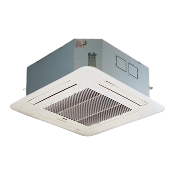
- Page 1 Ceiling Cassette Air Conditioner SERVICE MANUAL MODELS: TT-C186HLA0 TT-C186HLF0 TT-C246FLA0 TT-C246HLA0 TT-H246FLA0 TT-C246HLF0 TT-C368DLA0 TT-C368DLF0 TT-C428DLA0 TT-C488DLA0 TT-H488DLA0 TT-C488DLF0 TT-H368DLE1 TT-H488DLE1 TT-C488DLE1 TT-C366DLE1 TT-H488DL 1...
-
Page 2: Table Of Contents
Contents Model Identification .........................3 Functions ..........................4 Product Specifications (Cooling & Heating) ................7 Dimensions ..........................11 Refrigeration Cy cle Di agram ....................17 Wiring Di agram ........................18 Operation Details ........................21 Installation of Indoo r, Outdoor Unit ..................24 Test Running ......................... 35 3-Way Valve ........................... 39 Cycle ............................44 Cycle Troubleshooting Guide ....................47... -
Page 6: Functions
Remote Controller Wireless Remote Controller(Only for “ PLASMA” model Wired LCD Remote Controller Signal transmitter AUTO SWING OPERATION SET TEMP FAN SPEED SUB FUNCTION Room Temp Preheat Defrost Filter Out door 1 2 3 4 Time ZONE Program set Timer Set no. -
Page 7: Product Specifications (Cooling & Heating)
Product Specifications Item LG Model TT-C186HLA0 TT-C186HLF0 TT-H246FLA0 TT-C246HLA0 kcal/hr(W) 4,730(5,500) 4,537(5,275) 6,049(7,034) 6,106(7,100) Cooling Capacity 18,769 18,000 24,000 24,229 Btu/hr kcal/hr(W) 6962(8095) Heating Capacity Btu/hr 28,000 1950/- 1950/- 2700/2900 2500/- Input Cooling/Heating Running Current Cooling/Heating 9.5/- 9.5/- 12.3/18.2 11.5/-... -
Page 8: Dimensions
Product Specifications Item LG Model TT-C246HLF0 TT-C368DLA0 TT-C368DLF0 TT-C428DLA0 TT-C246FLA0 6,049(7,034) 6,049(7,034) kcal/hr(W) 9,074(10,551) 9074(10,551) 10586(12,309) Cooling Capacity Btu/hr 24,000 36,000 36,000 42,000 24,000 kcal/hr(W) Heating Capacity Btu/hr 2500/- 2700/- Input Cooling/Heating 4600/- 4600/- 4600/- Running Current Cooling/Heating 11.5/- 8.0/- 8.0/-... - Page 9 Product Specifications Item LG Model TT-C488DLA0 TT-C488DLF0 TT-H488DLA0 TT-H368DLE1 kcal/hr(W) 12,097(14,066) 12,097(14,066) 11,138(12,953) 10,315(12,000) Cooling Capacity Btu/hr 48,000 48,000 44,200 40,933 kcal/hr(W) 12,751(14,829) 11,089(12,899) Heating Capacity Btu/hr 44,000 50,600 Input Cooling/Heating 4800/- 4800/- 4800/5400 4200/4400 Running Current Cooling/Heating 8.0/- 8.0/- 8.0/9.0...
- Page 10 Product Specifications Item LG Model TT-H488DLE1 TT-C488DLE1 TT-C366DLE1 TT-H488DLF1 kcal/hr(W) 12,105(14,076) 12,105(14,076) 9,079(10,557) 12,105(14,076) Cooling Capacity Btu/hr 48,000 48,000 36,000 48,000 kcal/hr(W) 12,804(14,888) 12,804(14,888) Heating Capacity Btu/hr 50,800 50,800 Input Cooling/Heating 5300/5300 5100/- 4400/- 5300/5300 Running Current Cooling/Heating 9.0/9.0 9.0/9.0...
- Page 11 –1 –...
- Page 12 TD/TD1 Series Ceiling Opening 875 ( Hanging Bolt 785( : mm) Descripition Number Name Liquid pipe connection ø6.35 ø9.52 Gas pipe connection ø15.88 ø19.05 Drain pipe connection ø25/ø32 ø25/ø32 Power supply connection Air discharge grill Air suction grill –12–...
- Page 13 –13–...
- Page 14 –14–...
- Page 15 liquid side gas side TT-C368DLA0 TT-C368DLF0 TT-C428DLA0 TT-H368DLE1 Model TT-C488DLA0 TT-C488DLF0 TT-H488DLA0 TT-H488DLE1 TT-H488DLF1 TT-C488DLE1 1225 1135 –1 5–...
- Page 16 Model TT-C366DLE1 –16–...
-
Page 17: Refrigeration Cycle Diagram
Heat Exchanger Heat Exchanger Comp. Gas side * Refrigerant Diametor Height(m) Length (mm) Charge Model Liquid Standard Max. Max. (g/m) Standard TT-C186HLA0 15.88 6.35 TT-C186HLF0 TT-C366DLE1 TT-C246HLA0 TT-C246HLF0 15.88 6.35 TT-H246FLA0 TT-C246FLA0 TT-C368DLA0 TT-C368DLF0 TT-C428DLA0 TT-C488DLA0 15.88 9.52... -
Page 18: Wiring Diagram
Wiring Diagram TT-C186HLA0 TT-C186HLF0 Indoor Unit Wiring Diagram Outdoor Unit Wiring Diagram MOTOR capacity CENTRAL CONTROL ELEVATION GRILL NET CONTROL FLOAT SWITCH COMP. MOTOR INDOOR TEMP THERMISTOR MAIN PCB YL/GR PIPE TEMP Relay THERMISTOR RD YL WIRED REMOTE CONTROLLER BL BL... - Page 19 TT-H488DLA0 TT-C368DLA0 TT-C428DLA0 TT-C488DLA0 Outdoor Unit Wiring Diagram Indoor Unit Wiring Diagram 250V 10A) FUSE( PIPE TEMP THERMISTOR YL/GR NONC FUSE( 250V 10A) DRAIN INDOOR TEMP Defrosting PCB STEP CAPACITY MOTOR PUMP MOTOR THERMISTOR TERMINAL A PIPE TEMP RELAY THERMISTOR RELAY YL/GR TERMINAL1...
- Page 20 TT-C366DLE1 OUTDOOR UNIT WIRING DIAGRAM Indoor Unit Wiring Diagram BLDC MOTOR CENTRAL CONTROL ELEVATION GRILL NET CONTROL FLOAT SWITCH INDOOR TEMP THERMISTOR Magnet YL/GR MAIN PCB Switch PIPE TEMP THERMISTOR WIRED REMOTE CONTROLLER STEP DRAIN STEP DISPLAY PCB MOTOR PUMP MOTOR YL/GR AIR CLEANER...
- Page 24 –24–...
- Page 26 –26–...
- Page 29 ELECTRICAL WIRING Power Cable Of Indoor Unit Cable Of Controller Cover Controller Clamp Cover Controller Fisation Bolt (5set) Air Sunction Side Diagrams Cooling Only Model Terminal Block of Indoor Unit Terminal Block of Outdoor Unit 1(L) 2(N) POWER INPUT 220-240V 50Hz Terminal Block of Indoor Unit Terminal Block of Outdoor Unit 42k/48k...
-
Page 46: 3-Way Valve
3. Gas Charging (After Evacuation) Liquid side Indoor unit Outdoor unit Open 2-Way valve Gas side Open 3-Way valve Check valve Charging cylinder OPEN CLOSE • Procedure This is different from previous procedures. (1) Connect the charge hose to the charging Because you are charging with liquid refrigerant cylinder. -
Page 47: Cycle
Cycle Troubleshooting Guide Trouble analysis 1. Check temperature difference between intake and discharge air and operating current. Temp. difference : approx. 0°C All amount of refrigerant leaked out Current : less than 80% of Check refrigeration cycle rated current Temp. Difference Refrigerant leakege Temp. - Page 49 Possible Trouble 2 : The indoor fan does not operate. Is it the HOT It is normal operation. START mode? Is IC01M operated Exchange IC01M. normally? Is the each Relay Exchange Relay. any problem? Check the fan motor and connector.(CN-MOTOR) Possible Trouble 3 : Ineffective Heating Adjust operation mode.
-
Page 51: Electronic Control Device
Electronic control device TT-C368DLA0 TT-C428DLA0 TT-C488DLA0 TT-C246FLA0 –51–... -
Page 52: Schematic Diagram
Schematic Diagram TT-C246FLA0 – 52–... - Page 55 TT-H488DLE1 TT-C488DLE1 TT-C366DLE1 TT-H 48 8 DLF1 –55–...
- Page 56 249951 268711 354211 158591 352118 349480 552111 –56–...
- Page 57 130413 346810 130911-1 130911-3 352150-1 130911-2 267110 352150-1 –57–...
- Page 58 Location DESC. TTNC366DLE1 SVC Code 130413 Base Assembly,Weld(Indoor) 3041A10075B 130911-1 Cabinet Assembly,Indoor 3091A10082D 130911-3 Cabinet Assembly,Indoor 3091A10031K 352150 Hose Assembly,Drain 5251A10003D 130911-2 Cabinet Assembly,Indoor 3091A10082E AHA36957801 158591 Pump Assembly,Water *R*5859A10006B 249310 Holder Assembly 4931A20003E 354211 Evaporator Assembly,Bending 5421A10061E 349480 Orifice 4948A20039B 346810 Motor Assembly,DC,Indoor...
-
Page 59: Exploded View And Replacement Parts List
Exploded View and Replacement Parts List TD/TD1 349480 249951 268711 354211 552111 567480 352118 158591 –59–... - Page 60 TD/TD1 346810 359012 140570 137211 130911-3 130911-1 130911-2 352150-1 352150-2 267110 249310 –60–...
- Page 61 DESC TTNH368DLE1 TTNC488DLE1 TTNH488DLE1 130413 Base Assembly,Weld(Indoor) 3041A10075B 3041A10075B 3041A10075B 130911-1 Cabinet Assembly,Indoor 3091A10082D 3091A10082D 3091A10082D 130911-2 Cabinet Assembly,Indoor 3091A10082E 3091A10082E 3091A10082E AHA36957801 158591 Pump Assembly,Water AHA36957801 AHA36957801 *R*5859A10006B 130911-3 Cabinet Assembly,Indoor 3091A10031K 3091A10031K 3091A10031K 352150 Hose Assembly,Drain 5251A10003D 5251A10003D 5251A10003D 359012 Fan,Turbo...
- Page 62 Outdoor unit UH Chassis … 62…...
- Page 63 LOCATION DESC. TTUC488DLE1 TTUH488DLE1 TTUH368DLE1 SVC 430411 Base Assembly,Weld(Outdoor) AAN30302402 AAN30302402 AAN30302402 552203-1 Valve,Service MJX39498601 MJX39498601 5220A20033A 552203-2 Valve,Service 2A00393Q 2A00393Q 2A00393Q 435511 Cover Assembly,Control(Outdoor) 3551A20205A 3551A20205A 3551A20205A 554031 Condenser Assembly,Bending 5403A20123G 5403A20223C 5403A20223C 552115-1 Tube Assembly,Menifold(Outdoor) 5211A21055C 5211A23310A 5211A23310A 552115-2 Tube Assembly,Menifold(Outdoor) 5211A21054C 5211A13315H...
- Page 64 UE1 Chassis …64…...
- Page 65 Location DESC. TTUC366DLE1 SVC Code 447910 Barrier Assembly,Outdoor 2A01043L 435300 Grille,Rear 1A00208J 137213-1 Panel Assembly,Side 3721A20256A 137213-2 Panel Assembly,Side 3721A20257C 437211 Panel Assembly,Front(Outdoor) 3721A30061A 437210 Panel Assembly,Front(Sub) 3721A21012B 435301 Grille,Discharge 3530A20007M 349480 Orifice 4948A20005C 435512 Cover Assembly,Top(Outdoor) 3551A30033A 435512 Cover 2A00915R 349600 Bracket,Motor...