Table of Contents
Advertisement
Quick Links
2000W POWER INVERTER CT1398
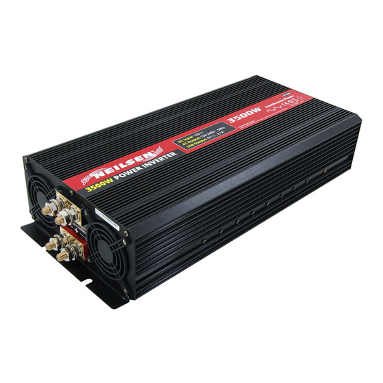
3500W POWER INVERTER CT1399
IMPORTANT:
These instructions accompanying the product are the original instructions. This
document is part of the product, keep it for the life of the product passing it on to
any subsequent holder of the product. Read all these instructions before
assembling, operating or maintaining this product.
Cannon Tools Limited
Address: 20 Station Road, Rowley Regis, West Midlands, B65 0JU.U.K.
INSTRUCTION MANUAL
Ref no. CAR2K
Ref no. CAR3.5K
Advertisement
Table of Contents

Summary of Contents for Neilsen CT1398
- Page 1 2000W POWER INVERTER CT1398 Ref no. CAR2K 3500W POWER INVERTER CT1399 Ref no. CAR3.5K INSTRUCTION MANUAL IMPORTANT: These instructions accompanying the product are the original instructions. This document is part of the product, keep it for the life of the product passing it on to any subsequent holder of the product.
-
Page 3: Ec Declaration Of Conformity
In case of alteration of the machine, not agreed upon by us, this declaration will lose its validity. Product description: 2000W POWER INVERTER Model: CT1398(Ref no. CAR2K) Product description: 3500W POWER INVERTER Model: CT1399(Ref no. CAR3.5K) Applicable EC Directives:... -
Page 5: Specification
Read this guide before install and use the power inverter, and please reserve it for future reference. 2. SPECIFICATION Model CT1398 CT1399 Rated power 2000W 3500W Surge power(few seconds) -
Page 6: Important Safety Instructions
3. IMPORTANT SAFETY INSTRUCTIONS Important:Read and save this owner’s guide for future reference. This chapter contains important safety and installation instructions for our MS and MSD series power inverters. Each time, before using the power inverter, read all instructions and cautionary marking on or provided with inverter and all appropriate sections of this guide. - Page 7 Notes: 1. Follow these instructions and those published by the battery manufacturer and the manufacturer of any equipment you intend to use in the vicinity of the battery. Review cautionary markings on these products and on the engine. 2. The inverter contains components which tend to produce arcs or sparks. 3.
-
Page 8: Protection Features
4. PROTECTION FEATURES Our power inverters are equipped with numerous protection features to guarantee safe and trouble-free operation: Alerts you if the battery has become Low battery alarm discharged to 10.5V or lower. Shuts the inverter down automatically if the battery voltage drops below 9.5 Low battery voltage shutdown volts. -
Page 9: Principle Of Operation
5. LOCATION The power inverter must only be installed in a location that is: The inverter must be installed in a dry location not subject to moisture especially rain, spray, or splashing bilge water. Cool The inverter should not be exposed to metal fillings or any other form of contamination. - Page 10 Materials List There is power inverter unit, user manual, DC cables and spare fuse inside of packing. 1.1 Modified sine wave power inverter CT1398 CT1399 Indication: 1) AC outlets are used to power loads. Please see the picture as follows, the output AC output type optional.
- Page 11 the battery via a negative DC input cable (black battery cable).the negative DC input terminal is colored black. 7) Positive DC input terminal(+) always connects to the positive terminal of the battery via a positive DC input cable (red battery cable).the positive DC input terminal is colored red.
- Page 12 8. THE INVERTER’S OUTPUT WAVEFORM The AC output waveform of the CAR series inverter is known as “modified sine wave” Modified sine wave and pure sine wave comparison The modified sine wave has an RMS (Root mean square) voltage of 220-240 volts, which is the same as standard household power.
- Page 13 1. Make sure that the chassis ground screw on the rear of the inverter is solidly connected to the ground system of your vehicle or home. 2. Make sure that the television antenna provides an adequate (“snow-free”) signal and that you are using good quality cable between the antenna and the television.
- Page 14 some exceptions to brief operating times are lamps, TVs and computers. Important: The power inverter must be connected only to batteries with a normal output voltage of 12 volts when you use a 12V inverter. The unit will not operate from a 6 volt battery, and will sustain permanent damage if connected to a 24 volt battery.
- Page 15 Wiring batteries in a series increases the total battery bank output voltage. A series connection combines each battery in a string until the voltage matches the inverter’s DC requirement. Even though there are multiple batteries, the capacity remains the same. In the example below , two 6VDC/200Ah batteries are combined into a single string-resulting in a 12VDC /200Ah bank.
-
Page 16: Mounting And Connecting The Inverter
A series-parallel configuration increases both voltage (to match the inverter’s DC requirements) and capacity (to increase run time for operating the loads) using smaller, lower voltage batteries. In the example below, four 6 VDC/200Ah batteries are combined into two strings resulting in a 12VDC/400Ah battery bank. 9.4. - Page 17 located on the front panel are visible and accessible. If inverter is to be installed in a moving vehicle, we strongly recommends that the inverter be shock-mounted either on the floor (in a clear, safe area) or on a secure flat surface.
- Page 18 a). Check to be sure the inverter’s power switch is turned off and that no flammable fumes are present. b). Identify the positive (+) and negative (-) battery terminals. c). Install a fuse holder or breaker close to the positive (+) terminal of the battery. d).
- Page 19 Caution: The inverter is engineered to be connected directly to standard electrical and electronic equipments. Do not connect the power inverter to household or RV AC distribution wiring.Do not connect the power inverter to any AC load circuit in which the neutral conductor is connected to ground(earth) or to the negative of the battery source.
-
Page 20: Fuse Replacement
12.FUSE REPLACEMENT The inverter protected by our integral electronic circuit and will automatically reset. More than that, this inverter is equipment with a fuse that is located inside the inverter. If reverse polarity connection, the fuse burn. Please you need open the bottom to replace the fuse. -
Page 21: Troubleshooting
13. TROUBLE SHOOTING No AC output; red LED lit, green LED not lit Possible Cause Suggested Solution DC input below 10volts(battery low voltage) Recharge or replace battery Inverter overheat thermal shutdown Remove or reduce load, wait for inverter to cool No AC output;... - Page 22 The inverter only working with smaller AC appliances Possible Cause Suggested Solution The current dissipation too much in DC Use heavy cables and shorten the cables cables Low battery alarm sounds abnormal Possible Cause Suggested Solution Bad connection or wiring Tighten all DC connections Low battery alarm sounds Possible Cause...
-
Page 23: Maintaining The Inverter
14. MAINTAINING THE INVERTER Minimal maintenance is required to keep your inverter operating properly, periodically you should: 。Clean the exterior of the unit with a damp cloth to prevent the accumulation of dust and dirt. 。Ensure that DC cables are secure and fasteners are tight 。Make sure the ventilation openings on the DC panel and bottom of the inverter are not clogged. - Page 24 CANNON TOOLS LTD Add: 20 station road, Rowley Regis, west midlands,B65 0JU.U.K. Made in China...