
Related Manuals for HP X27i


Summary of Contents for HP X27i
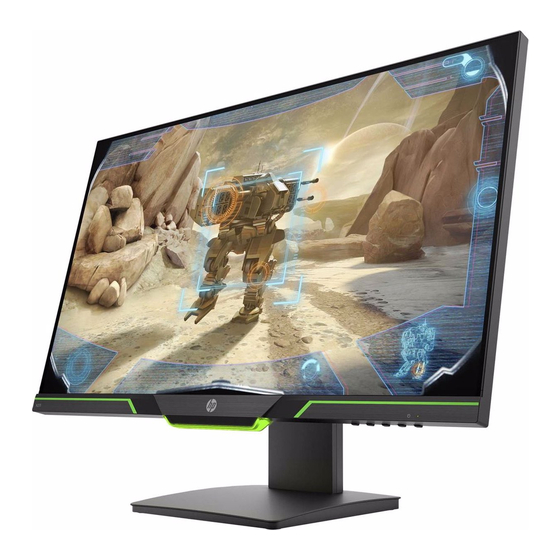
- Page 1 Maintenance and Service Guide X27i model SUMMARY This guide provides information about spare parts, removal and replacement of parts, diagnostic tests, problem troubleshooting, and more.
- Page 2 Company, L.P. AMD is a trademark of Advanced Micro Devices, Inc. Bluetooth is a trademark owned by its proprietor and used by HP Inc. under license. NVIDIA is a trademark and/or registered trademark of NVIDIA Corporation in the U.S. and other countries.
-
Page 3: Table Of Contents
Table of Contents 1 Getting started .................................... 2 Important safety information ................................2 Important service information and precautions .......................... 3 RoHS (2002/95/EC) requirements ..............................3 General descriptions..................................4 Firmware updates ....................................4 Before returning the repaired product to the customer ......................4 2 Monitor features .................................. -
Page 4: Getting Started
1 Getting started Read this chapter to learn about safety information and where to find additional HP resources. Important safety information Carefully read the cautions and notes within this document to minimize the risk of personal injury to service personnel. The cautions and notes are not exhaustive. Proper service methods are important to the safe, reliable operation of equipment. -
Page 5: Important Service Information And Precautions
Important service information and precautions ● Repair must be performed by professional service technicians in a repair center. End users should not perform these procedures. ● Please note during servicing that the primary side is the high voltage area. ● This monitor meets ROHS requirements. -
Page 6: General Descriptions
Level 2: Circuit board or standard parts replacement Firmware updates Firmware updates for the monitor are available at support.hp.com. If no firmware is posted, the monitor does not need a firmware update. Before returning the repaired product to the customer Perform an AC leakage current check on exposed metallic parts to be sure the product is safe to operate without the potential of electrical shock. -
Page 7: Monitor Features
On-screen display (OSD) adjustments in several languages for easy setup and screen optimization HP Display Assistant software for adjusting monitor settings and enabling the theft deterrent features HDCP (High-bandwidth Digital Content Protection) copy protection on all digital inputs ... -
Page 8: Front Components
Front components To identify the components on the front of the monitor, use this illustration and table. Table 1-1: Front components and their descriptions Component Function Menu button Press to open the OSD menu, select a menu item from the OSD, or close the OSD menu. When the OSD menu is open, the Menu light turns on. -
Page 9: Rear Components
Rear components To identify the components on the rear of the monitor, use this illustration and table. Table 1-2: Rear components and their descriptions Component Function Power connector Connects the power cord. Connects optional powered stereo speakers, Audio-out (headphone) jack headphones, earbuds, or a television audio cable. -
Page 10: Locating The Serial Number And Product Number
The serial number and product number are located on a label on the back of display. You may need these numbers when contacting HP about the monitor model. Note: You may need to partially pivot the display head to read the label. -
Page 11: Illustrated Parts Catalog
3 Illustrated parts catalog To identify the monitor major components, use this illustration and table. Table 2-1: Monitor major components and their descriptions Item Description ASSY MF X27i BTN ABS AMBIENT LENS PCBA CTRL BD PCBA LENS BD PANEL PCBA IF BD... -
Page 12: How To Order Parts
You can purchase cables from the HP part store at https://partsurfer.hp.com/Search.aspx. NOTE: HP continually improves and changes product parts. For complete and current information about supported parts for your computer, go to http://partsurfer.com, select your country or region, and then follow the on-screen instructions. -
Page 13: Removal And Replacement Procedures
4 Removal and replacement procedures Adherence to these procedures and precautions is essential for proper service. Preparation for disassembly Use this information to properly prepare to disassemble and reassemble the monitor. Use this information to properly prepare to disassemble and reassemble the monitor. 1) Clean the room for disassembly. -
Page 14: Rear Cover
Disassembly procedure Rear Cover item picture Operation Tool Notes Screw- 11.0±1.0 1. Unlock 4 screws driver Disassemble the RC from the monitor, notice the disassembly order: 1. Unlock 1 screw 4.5±0.5K 1.Disassemble the Bottom part 2.Disassemble the Right part 3. Remove RC from panel. 1. - Page 15 1. Remove lamp wire from panel 2. Remove Lens cable from panel 3. Disassemble Lens BD from MF 4. Remove Lens cable from Lens BD 5. Remove Ctrl cable from panel 6. Disassemble Ctrl BD from MF 7. Remove CTRL cable from CTRL BD 1.
- Page 16 1. Unlock 7 screws 2. Disassemble IF BD and SPS BD from SHD Screw- 7±1Kg 3. Remove power wire driver IF BD from IF BD 1. Remove 4 LVDS wire from IF BD IF BD...
-
Page 17: Power Board
Locate PN on the red frame as follow image. • Power Board IMPORTANT: Repairing must operate by professional repairers in HP repair center, not applicable • for end user The primary side is the high voltage area, please take care when repair (Front and •... - Page 18 Power board Repair Condition: Capacitor repair is only for the monitor that has been out of warranty period. IMPORTANT: • Repairing must operate by professional repairers (Note) in repair center, not applicable for end user • The primary side is the high voltage area, please take care when repair (Front and Back view) •...
- Page 19 Repair Process: When EL capacitors damage or explode, it may lose function and cause product no work The C707, C708 and C709 locations are identified below: C708 C707 C709 Power Board 1) You must disconnect the power cord from the power source before opening the monitor to prevent component damage.
- Page 20 3) Lift capacitors from the PCB. Power Board 4) Place new component on the location, and must check polarity match PCB print. 5) After repaired, please double check whether polarity match PCB print, solder empty and unnecessary solder after soldering must remove.
-
Page 21: Connector Repair
Connector repair This procedure includes Audio, HDMI and Display port connectors. • The connectors are on the IF board (board part number 5E.4NT01.001, 5E.4NT01.002, • 5E.4NT01.011, 5E.4NT01.012, 5E.4NT01.013). The connectors identifiers are as follows: • Connector Location Audio M590 HDMI DisplayPort Main Board Before repairing connectors, follow these steps:... -
Page 22: Audio Connector Repair- M590
Audio Connector repair- M590 Use a hot air gun to melt the solder on the pins Pin solder with soldering iron and absorber. You can gently push down with the soldering iron once everything is molten to move the M1 out of the through holes 2). -
Page 23: Hdmi Connector Repair- J5
HDMI Connector repair- J5 1) Use a soldering iron and a de-soldering pump to remove as much solder as possible from one of the pin. 2) Use a hot air gun to melt the solder on the pins 3). Lift J2 from the PCB 4). -
Page 24: Dp Connector Repair- J3
DP Connector repair- J3 Use a soldering iron and a de-soldering pump to remove as much solder as possible from one of the pin. Use a hot air gun to melt the solder on the pins Lift J3 from the PCB Place new component on the location, and must check it can match PCB footprint Soldering the new component by solder iron Tear off the yellow tape on the DP connector, so that it can contact to the gasket, EMI will be... -
Page 25: Stick Gasket On The Shielding
Stick Gasket on the Shielding 1) Use scissors to cut the length of gasket 3021717 in 20mm. Gasket Size: W 17mmx x H 17mm x L 20mm (The Length of gasket should not be less than 20mm) 2) Remove the tape on the gasket and align the gasket to the right side of the HDMI or DP. (Alignment refers to the arrow in the image below) 3) Press the gasket to the end of shielding with your fingers and confirm that it will not fall. -
Page 26: Function Test
Function test After repair, be sure to confirm that all functions are working. Table 4-1: Function test Test item Operating description Tool used HDMI test Confirm whether image displays and sound Computer or DVD player plays correctly on the monitor. DP test Confirm whether image displays and sound Computer or DVD player... -
Page 27: Support And Troubleshooting
Support and troubleshooting The following table lists possible problems, the possible cause or each problem, and the recommended solutions. Table 4-2: Solving common problems Problem Possible cause Solution Screen is blank or Power cord is disconnected. Connect the power cord. video is flashing. -
Page 28: Index
Index components parts, 9 front, 6 parts, ordering, 10 rear, 7 power board removal, 15 connector repair, 19 power button location, 6 power connector location, 7 precautions, 3 preparation for disassembly, 11 DisplayPort connector location, 7 RC removal, 12 rear components, 7 features, 5 removal firmware updates, 4...