
Related Manuals for Midland 70-066


Summary of Contents for Midland 70-066
- Page 1 Midland 70-066 Conversion 6 Meters Introduction Ver 1.8 – 07 Nov 2009 Part 1 Rod McCosker VK2DOT Midland 70-066 low Band Conversion to 6 Meters: Part 1 Page 1...
- Page 2 Part 1: Acknowledgment: Modifications: Parts Needed: Test Equipment needed. Information about Midland 70-066 6 Meter Midland 70-066 FM Frequencies – 62 channel EPROM. EPROM Software: Part 2: The Synthesizer Board including EPROM board. Z-273 EPROM Board: The Synthesizer Board. Synthesizer Alignment.
-
Page 3: Parts Needed
Acknowledgment: This project was started in June 2008 on for amateurs interested in the use of the Midland 70-066 commercial radio transceiver. The conversion of the said transceiver to 6 Meters for amateur radio. Acknowledgement must be given to:- Steve VK2KFJ, Peter VK2ZZA, Roger Baker VK3BKR, Mark Detering VK3TLW, Phil Rice VK3BHR, Mark VK3BYY, Phil VK1PL &... - Page 4 The Z-273 EPROM Modifications and Synthesizer Modification must be done first, before alignment can be done. It is advisable that members split into groups, doing an event for each group. Midland 70-066 low Band Conversion to 6 Meters: Part 1 Page 4...
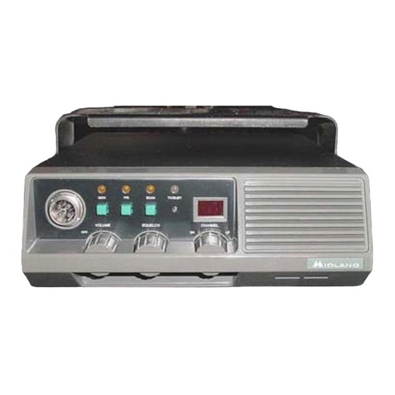
- Page 5 66-80 mhz 40 watt Trunk Mount mid band Models = A-66-80 Mhz B-75-88 Mhz Above –Midland 70-066 Front View, Above –Midland 70-076 Front View, Above –Midland 70-076 Case View, Midland 70-066 low Band Conversion to 6 Meters: Part 1 Page 5...
- Page 6 Above – Bottom View Above – Top View Midland 70-066 low Band Conversion to 6 Meters: Part 1 Page 6...
- Page 7 35 0 52.900 53.900 Reverse channel #15 36 0 52.925 53.925 Reverse channel #16 37 0 52.950 53.950 Reverse channel #17 38 0 52.975 53.975 Reverse channel #18 Midland 70-066 low Band Conversion to 6 Meters: Part 1 Page 7...
- Page 8 55 0 53.400 53.400 56 0 53.425 53.425 57 0 53.450 53.450 58 0 53.475 53.475 59 0 53.500 53.500 60 0 53.525 53.525 Repeater Simplex 61 0 53.559 53.550 Midland 70-066 low Band Conversion to 6 Meters: Part 1 Page 8...
- Page 9 Binary file for EPROM burning using 62 Channel frequency listing. Software. Software Description: The VK2DOT Midland 6 meter firmware generator Software has the following functions and restrictions:- Software will operate under DOS or Windows & from a floppy or hard drive or from a USB stick.
- Page 10 Signal Generator to cover 50Mhz to 88Mhz. Testing. Hopefully, your Midland 70-066 has an installed EPROM. And the EPROM has not been erased, If this is TRUE then; Connect your transceiver to a 12 Volt power supply and the antenna to power meter and dummy load. Go to channel 1;...
- Page 11 DC cable for synthesizer testing. 1 cable - black banana plug to alligator clip. 1 cable - red banana plug to red clip. UV Light assembly for bulk erasing of Z-273’s 2716 EPROM’s. Midland 70-066 low Band Conversion to 6 Meters: Part 1 Page 11...
- Page 12 The Synthesizer including EPROM Board. Midland70-066 Sync Board Top View - below: Remove the EPROM board [above as Z-273], reverse view below. Midland 70-066 low Band Conversion to 6 Meters: Part 1 Page 12...
- Page 13 NOTE: For the CTCSS and receiver to work properly [ie audio out to speaker to work] on the Midland 70-066 transceivers – Make sure the 8 pin plug is plugged into the white 8 pin socket J903 on the Z-273 EPROM board.
- Page 14 Midland 70-066 Sync Board Top View below: TX buffer, remove L114 and keep for use on the PA board; replace with 7.5 turns of 0.5mm wire, same diameter former. Midland 70-066 low Band Conversion to 6 Meters: Part 1 Page 14...
- Page 15 Midland 70-066 Sync Board Bottom – Unsolder Bottom Plates: Midland 70-066 low Band Conversion to 6 Meters: Part 1 Page 15...
- Page 16 Midland 70-066 Sync Board Bottom View Capacitors - below: C137 C709 RX (main) VCO, add 22pF to C709. TX (offset) VCO, add 22pF to C137 [for Midland 70-066], located under VCO cover on the track side of the board. Some transceivers may require more. RX buffer amp, add 5.6pF to primary of L709...
- Page 17 Midland 70-066 Sync Board Bottom View New Capacitors - below: Midland 70-066 low Band Conversion to 6 Meters: Part 1 Page 17...
- Page 18 TP741 will be 6 V or less than 1.7 V. If the PLL is locked, either the first channel number will be displayed or else the unit will wait blank on channel 00 [for RT85] or 01 [for Midland 70-066A] until either the UP or DOWN button is pressed.
- Page 19 Receiver Local Oscillator output from J365. Midland 70-066 low Band Conversion to 6 Meters: Part 1 Page 19...
- Page 20 Midland 70-066 Conversion 6 Meters Ver 2.9 – 16 Nov 2009 Part 1 Rod McCosker VK2DOT Midland 70-066 low Band Conversion to 6 Meters: - Introduction Part 1 Page 1.1...
- Page 21 Part 6A: The Midland 70-066 Manual 1 Part 6B: The Midland 70-066 Manual 2 Part 6C: The Midland 70-066 Manual 3 Part 6D: The Midland 70-066 Manual 4 Midland 70-066 low Band Conversion to 6 Meters: - Introduction Part 1 Page 1.2...
-
Page 22: Please Read This
NOT reading this documentation before or during the conversion. If any mistakes are found, or a suggestion for a better document, please send your comments to:- vk2dot@tpg.com.au Midland 70-066 low Band Conversion to 6 Meters: - Introduction Part 1 Page 1.3... - Page 23 Acknowledgement must be given to:- Steve VK2KFJ, Peter VK2ZZA, Roger Baker VK3BKR, Mark Detering VK3TLW, Phil Rice VK3BHR, Mark VK3BYY, Phil VK1PL who converted me to the Midland family of transceivers, Andrew VK4OX for the information gained from their past documentation and generous guidance. Warwick VK4NW for the PA Modifications.
- Page 24 Small plastic bag to keep screws and coils in. A4 plastic bag to keep covers in. 12 volt power cable with Molex plug [approx 1 meter] if a Midland 70-066 and an in-line 10Amp fuse, will be needed in aprox three weeks for testing the transceiver.
-
Page 25: Test Equipment Needed
For members not savvy with the use of Test Equipment, please find an amateur who will be available to guide you in alignment procedures. Midland 70-066 low Band Conversion to 6 Meters: - Introduction Part 1 Page 1.6... -
Page 26: Synthesizer Board
Place transmitter PA PCB back into transceiver. --- Align transmitter PA. Check on air. *** = Use of de-soldering station. ### = Use of soldering iron. = Use of test equipment. Midland 70-066 low Band Conversion to 6 Meters: - Introduction Part 1 Page 1.7... - Page 27 Models = A-66-80 Mhz B-75-88 Mhz Above - Front View of Midland 70-066A with Local Head, Above – Bottom View of Midland 70-066A with Local Head: Midland 70-066 low Band Conversion to 6 Meters: - Introduction Part 1 Page 1.8...
- Page 28 Above –Midland 70-076 Case View, Above – Midland 70-076 with Remote Head: Midland 70-066 low Band Conversion to 6 Meters: - Introduction Part 1 Page 1.9...
- Page 29 Above – Bottom View of Midland 70-066 Receiver side with Local Head: Above – Top View of Midland 70-066 Receiver side with Local Head: Midland 70-066 low Band Conversion to 6 Meters: - Introduction Part 1 Page 1.10...
- Page 30 Reverse channel # 1 22 0 52.5750 53.5750 Reverse channel # 2 23 0 52.6000 53.6000 Reverse channel # 3 24 0 52.6250 53.6250 Reverse channel # 4 Midland 70-066 low Band Conversion to 6 Meters: - Introduction Part 1 Page 1.11...
- Page 31 56 0 53.4250 53.4250 57 0 53.4500 53.4500 58 0 53.4750 53.4750 59 0 53.5000 53.5000 60 0 53.5250 53.5250 Repeater Simplex 61 0 53.5500 53.5500 Midland 70-066 low Band Conversion to 6 Meters: - Introduction Part 1 Page 1.12...
- Page 32 Apply to the surface to be de-soldered with a small brush, old toothbrush or icy pole stick. We have found that a wooden tooth pick has been the most successful method of applying the Bugs Juice to the pin requiring de-soldering. Midland 70-066 low Band Conversion to 6 Meters: - Introduction Part 1 Page 1.13...
-
Page 33: Power Plug
Bands other than 6 Meters have to be checked. Power Plug: NOTE: If you do not jumper pins 5 & 6, your internal speaker will not work. The CCARC Midland 70-066B transceivers do not have power plugs. Midland 70-066 low Band Conversion to 6 Meters: - Introduction Part 1... - Page 34 NOTE: Connector WW’s are opposite red & black power leads. Brown lead is internal speaker loop. In the photo above, the WW’s are closest to the heat fins. Midland 70-066 low Band Conversion to 6 Meters: - Introduction Part 1 Page 1.15...
- Page 35 It has been suggested by Ken VK2KJ, that if you cannot locate a Molex plug for the midland 70-066 transceiver - Remove the power socket female pins by using a very small jeweler’s screwdriver to bend back the locking fins. This is made easier by reshaping the pin socket diameter to gain access to the fins.
- Page 36 Look at center coil above, run sharp object between legs. That is how you count turns on a coil. Remote cable for Midland 70-076 Head: NOTE: Connectors are reversed at the ends of the cable. [Computer cables work OK] Midland 70-066 low Band Conversion to 6 Meters: - Introduction Part 1 Page 1.17...
- Page 37 Signal Generator to cover 50Mhz to 88Mhz. Testing. Hopefully, your Midland 70-066 has an installed EPROM. And the EPROM has not been erased, If this is TRUE then; Connect your transceiver to a 12 Volt power supply and the antenna to power meter and dummy load. Go to channel 1;...
- Page 38 DC cable for synthesizer testing. 1 cable - black banana plug to alligator clip. 1 cable - red banana plug to red clip. UV Light assembly for bulk erasing of Z-273’s 2716 EPROM’s. Midland 70-066 low Band Conversion to 6 Meters: Synthesizer Part 2 Page 2.2...
- Page 39 The Synthesizer including EPROM Board. Midland 70-066 Sync Board Top View - below: Remove the EPROM board [above as Z-273], reverse view below. Midland 70-066 low Band Conversion to 6 Meters: Synthesizer Part 2 Page 2.3...
- Page 40 REMEMBER REPLACE EPROM in the RIGHT WAY on the Z-273 or the EPROM will blow & be USELESS Previous converters have done this. Midland 70-066 low Band Conversion to 6 Meters: Synthesizer Part 2 Page 2.4...
- Page 41 NOTE: For the CTCSS and receiver to work properly [ie audio out to speaker to work] on the Midland 70-066 transceivers – Make sure the 8 pin plug is plugged into the white 8 pin socket J903 on the Z-273 EPROM board.
- Page 42 TX buffer, remove L114 and keep for use on the PA board; replace with 7.5 turns of 0.63mm wire, same diameter former. [Use a 5mm drill bit to wind the new coil on.] Midland 70-066 low Band Conversion to 6 Meters: Synthesizer Part 2 Page 2.6...
- Page 43 Midland 70-066 Sync Board Bottom – Unsolder Bottom Plates: It is noticed that the Midland 70-066A & B models have only one shield on the bottom of the synthesizer board, the left one above. Midland 70-066 low Band Conversion to 6 Meters: Synthesizer Part 2...
- Page 44 TX (offset) VCO, add 22pF to C137 [for Midland 70-066], located under VCO cover on the track side of the board. Some transceivers may require more. RX buffer amp, add 5.6pF to primary of L709 Midland 70-066 low Band Conversion to 6 Meters: Synthesizer Part 2 Page 2.8...
- Page 45 Midland 70-066 Sync Board Bottom View New Capacitors - below: Re-solder bottom plates back onto bottom of Sync Board. Midland 70-066 low Band Conversion to 6 Meters: Synthesizer Part 2 Page 2.9...
- Page 46 Midland 70-066 low Band Conversion to 6 Meters: Synthesizer Part 2 Page 2.10...
- Page 47 Midland 70-066 low Band Conversion to 6 Meters: Synthesizer Part 2 Page 2.11...
- Page 48 If the PLL is locked, either the first channel number will be displayed or else the unit will wait blank on channel 01 [for Midland 70-066A] until either the UP or DOWN button is pressed. Midland 70-066 low Band Conversion to 6 Meters: Synthesizer Part 2...
- Page 49 4: Transmitter Driver Alignment: Connect a DC voltmeter to pin 2 of CM101. Set channel to center frequency. Ie. channel 48 [53.225Mhz]. Adjust CV102 for a dip between two peaks. Midland 70-066 low Band Conversion to 6 Meters: Synthesizer Part 2 Page 2.13...
- Page 50 Receiver Local Oscillator output from J365. Midland 70-066 low Band Conversion to 6 Meters: Synthesizer Part 2 Page 2.14...
- Page 51 Then remove all screws holding the receiver board to the transceiver chassis. NOTE: - Do not unsolder the power cables to the receiver board. Midland 70-066 Receiver Board - below. Midland 70-066 low Band Conversion to 6 Meters: Receiver Ver 2.1 20-nov-09 Part 3 Page 3.1...
- Page 52 RT85 Receiver Board Bottom below. Midland 70-066A Receiver Board Bottom Capacitors Added below. NOTE Above: C203 & C211 has been changed to 2.2pF for the Midland 70-066A Midland 70-066 low Band Conversion to 6 Meters: Receiver Ver 2.1 20-nov-09 Part 3 Page 3.2...
- Page 53 Short C210. Add 2.2pF to C203 and C211. Add 8.2pF to C201, C206, and C213. LO tuned buffer. Add 5.6pF to C220 and C223. Midland 70-066 low Band Conversion to 6 Meters: Receiver Ver 2.1 20-nov-09 Part 3 Page 3.3...
- Page 54 NOTE Above: C203 & C211 has been changed to 2.2pF for the Midland 70-066A NOTE Above: C211 has been changed to 2.2pF for the Midland 70-066A Midland 70-066 low Band Conversion to 6 Meters: Receiver Ver 2.1 20-nov-09 Part 3 Page 3.4...
- Page 55 Midland 70-066 low Band Conversion to 6 Meters: Receiver Ver 2.1 20-nov-09 Part 3 Page 3.5...
- Page 56 Midland 70-066 Receiver Board Bottom Capacitors below. [see larger diagram at end for printout] Midland 70-066 low Band Conversion to 6 Meters: Receiver Ver 2.1 20-nov-09 Part 3 Page 3.6...
- Page 57 Midland 70-066 Receiver Board Top Assembly View - below: Midland 70-066 low Band Conversion to 6 Meters: Receiver Ver 2.1 20-nov-09 Part 3 Page 3.7...
- Page 58 Midland 70-066 Receiver Board Bottom Capacitor View - below: Midland 70-066 low Band Conversion to 6 Meters: Receiver Ver 2.1 20-nov-09 Part 3 Page 3.8...
- Page 59 An alternative method is to use a Sinad meter or tune for maximum quieting. When correctly aligned the sensitivity is typically 0.35uV for 12db sinad over the range 52.5 to 54 MHz. Tests have concluded that the Midland 70-066 should lift the mute at 0.1uV for a reasonable audio quality.
- Page 60 4: At this point in time, it looks like the following amendment will be necessary for the capacitor across CV502:- 22pF for Midland 70-066A 33pF for Midland 70-066B Midland 70-066 low Band Conversion to 6 Meters: Transmitter PA Part 4 Ver 2.2 21Nov09 Page 1...
- Page 61 Midland 70-066 PA module above: The Midland 70-066 Transmitter PA stage swings down by unscrewing the two screws on the side of the PA stage. Then remove the top PA cover, by unscrewing the two screws at the bottom of the cover.
- Page 62 5mm. [NOTE: The new Jaycar wire, the enamel can be removed by heat. So instead of scraping wire, tin ends of wire with a soldering iron.) Wind onto a 5mm drill bit [the drill bit Midland 70-066 low Band Conversion to 6 Meters: Transmitter PA Part 4 Ver 2.2 21Nov09 Page 3...
- Page 63 Remove L513 and keep; replace with old cut back 2.5 turns of coil L519. [2.5 Turns] Remove original L512; replace with original L513. [1.5 Turns] Midland 70-066 low Band Conversion to 6 Meters: Transmitter PA Part 4 Ver 2.2 21Nov09 Page 4...
- Page 64 Midland 70-066 low Band Conversion to 6 Meters: Transmitter PA Part 4 Ver 2.2 21Nov09 Page 5...
- Page 65 Add 1.5pF to the RF sensor circuit (C554) on the underside of the board as per the photo. On the RT85 this capacitor is already fitted. Midland 70-066 low Band Conversion to 6 Meters: Transmitter PA Part 4 Ver 2.2 21Nov09 Page 6...
- Page 66 30 Watts out. If you wish to run 50 watts, then attach a 12 Volt fan to the rear heat sink. Allow the fan to blow across the rear fins. Midland 70-066 low Band Conversion to 6 Meters: Transmitter PA Part 4 Ver 2.2 21Nov09 Page 7...
- Page 67 PA Swung Back. Midland 70-066A Top cover still on – Above: PA Top View – Midland 70-066A Original Setup – Cover Removed - Above: Midland 70-066 low Band Conversion to 6 Meters: Transmitter PA Part 4 Ver 2.2 21Nov09 Page 8...
- Page 68 Remove L519. Cut back to 2.5 turns and keep coil to replace coil L513. Remove L513 and keep; replace with old cut back 2.5 turns of coil L519. Remove original L512; replace with original L513. Midland 70-066 low Band Conversion to 6 Meters: Transmitter PA Part 4 Ver 2.2 21Nov09 Page 9...
- Page 69 & ground of Q502 [2SC1971] Place 1000 pF across base & ground of Q503 [2SC2097] Place pF across CV501 Place pF across CV502 Place pF across CV503 Midland 70-066 low Band Conversion to 6 Meters: Transmitter PA Part 4 Ver 2.2 21Nov09 Page 10...
- Page 70 PA Bottom View – New Capacitors for Midland 70-066 - Above: Top of C526 [33pf] - scrape green off copper layer. PA Bottom View – New Capacitors for Midland 70-066 - Above: Midland 70-066 low Band Conversion to 6 Meters: Transmitter PA Part 4 Ver 2.2 21Nov09 Page 11...
- Page 71 PA Bottom View – New Capacitors for Midland 70-066 - Above: Top of C526 [33pf] - scrape green off copper layer. Midland 70-066 low Band Conversion to 6 Meters: Transmitter PA Part 4 Ver 2.2 21Nov09 Page 12...
- Page 72 PA PC Board – Top View – Above: PA PC Board – Top View – Above: Midland 70-066 low Band Conversion to 6 Meters: Transmitter PA Part 4 Ver 2.2 21Nov09 Page 13...
-
Page 73: Transmitter Alignment
1. Connect a lower power 50 ohm power meter to J366 [exciter output]. Go to channel 48 for center frequency. Connect a multimeter to TP101, [refer to the diagram above – The Synthesizer Board] and operate the microphone PTT button. Midland 70-066 low Band Conversion to 6 Meters: Transmitter PA Part 4 Ver 2.2 21Nov09 Page 14... - Page 74 3. Reduce the audio oscillator to 3mV rms at 1KHz. 4. Adjust RV102 for +-3KHz deviation. If necessary, repeat steps 1 and 2 above. Midland 70-066 low Band Conversion to 6 Meters: Transmitter PA Part 4 Ver 2.2 21Nov09 Page 15...