Advertisement
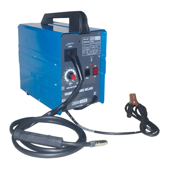
90 AMP Flux Wire Welder
Set uP And OPerAting inStructiOnS
distributed exclusively by Harbor Freight tools
Visit our website at: http://www.harborfreight.com
read this material before using this product.
Failure to do so can result in serious injury.
SAVe tHiS MAnuAl.
Copyright
2005 by Harbor Freight Tools
©
contained herein may be reproduced in any shape or form without the express written consent of
Harbor Freight Tools. Diagrams within this manual may not be drawn proportionally. Due to continuing
improvements, actual product may differ slightly from the product described herein. Tools required for
assembly and service may not be included.
For technical questions or replacement parts, please call 1-800-444-3353.
reV 06g, 09e, 09h
3491 Mission Oaks Blvd., Camarillo, CA 93011
. All rights reserved. No portion of this manual or any artwork
®
94056
.
®
Advertisement
Table of Contents

Related Manuals for Chicago Electric MIG-100 94056


Summary of Contents for Chicago Electric MIG-100 94056
- Page 1 90 AMP Flux Wire Welder Set uP And OPerAting inStructiOnS distributed exclusively by Harbor Freight tools 3491 Mission Oaks Blvd., Camarillo, CA 93011 Visit our website at: http://www.harborfreight.com read this material before using this product. Failure to do so can result in serious injury.
-
Page 2: Specifications
Both settings: 10 min. shutdown, 3 min. back on with Light 0.030”; Spare: Welder Tip 0.035”; Will also accept a 0.023” welder tip (not included) 0.030” flux core wire (using 0.030” Welder Tip) 4” diameter 14-1/2” (L) x 7-7/8” (W) x 15-1/2” (H) 34.45 lb. - Page 3 for which it was intended. Do not use inappropriate attachments in an attempt to exceed the tool capacity. use the right tool for the job not attempt to force a small tool or attachment to do the work of a larger industrial tool.
- Page 4 ANSI-approved. This unit draws enough current to cause serious injury or death. Before turning the welder on, check the electrode holder to be sure that there are no protruding screw heads, and that all insulation is secure. Do not weld unless you are insulated from ground and the work piece.
-
Page 5: Assembly
Know proper welding practices Read and understand the manufacturer’s instructions, as well as your employer’s safety practices for welding. connect only to a code approved power source. Connect only to a grounding power source conforming to the National Electrical Code and Local Codes. -
Page 6: Controls
10-minute period, during which a given welder can safely produce a particular welding current. For example, this 90 amp welder with a 10% duty cycle must be rested for at least 9 minutes after 1 minute of continuous welding. - Page 7 If too much current is drawn from the Welder, the Thermal Overload protector will activate, the amber indicator will light, and the Welder will turn off until it cools down. If this happens, turn the Power Switch to the OFF position and wait about 3 ~ 5 minutes.
-
Page 8: Replacing The Wire Reel
MAintenAnce caution: Before performing any maintenance on the Welder, unplug the Power Cord from the electrical outlet. Periodically remove the Right and Left side panels (12 and 13), and using compressed air, blow out all dust from the interior. Store in a clean and dry location. -
Page 9: Please Read The Following Carefully
Warning: The following steps require applying power to the welder. Do not touch anything with the Torch Handle or an arc may be ignited. Plug the Power Cord into its electrical outlet, press the Current Switch to Max., and turn the welder ON. -
Page 10: Parts List And Diagrams
PArtS liSt And diAgrAMS Part description Torch Contact Tip Nozzle Liner Fixing Pole (A) for Gun Body Fixing Pole (B) for Gun Body Switch Cover Locking Spring Knob Speed Control Circuit Board Right Side Panel Left Side Panel Base Frame Foot Washer Screw, ST 4.2 x 13... -
Page 11: Assembly Diagram
Assembly diagram SKU 94056 For technical questions, please call 1-800-444-3353. Page 11... -
Page 12: Welder Assembly
Welder Assembly Photographs reV 09e SKU 94056 For technical questions, please call 1-800-444-3353. Page 12... -
Page 13: Wiring Schematic
Wiring Schematic SKU 94056 For technical questions, please call 1-800-444-3353. Page 13... -
Page 14: Warranty
(if applicable), welding clamps, electrode holders, cables and accessories packed with the welder are free of defects in materials and workmanship. this limited 90 day/1 year Warranty shall not apply to consumable parts such as tips, welding wire, and gas nozzles.