
Related Manuals for Texas Instruments TIRIS RI-STU-MRD1


Summary of Contents for Texas Instruments TIRIS RI-STU-MRD1
- Page 1 Texas Instruments Registration Identification System Micro-reader RI-STU-MRD1 Reference Manual 11-06-21-027 25-July-1996...
- Page 2 This is the second edition of this manual, it describes the following equipment: TIRIS Micro-reader Module RI-STU-MRD1 Texas Instruments reserves the right to change its products or services at any time without notice TI provides customer assistance in various technical areas, but does not have full...
-
Page 3: Table Of Contents
25 July 1996 Micro-reader Module Contents 1. Introduction ................................5 1.1 General ................................5 1.2 Product Description ............................5 1.3 Product Option Coding .............................5 1.4 Conventions ..............................5 2. Product Function ..............................7 2.1 Description ...............................7 2.1.1 Power Supply ............................7 2.1.2 Antenna ..............................7 2.1.3 Synchronization ............................8 2.1.4 Trigger Mode ............................8 2.1.5 Continuous Mode ............................8 2.1.6 Serial Communication ..........................9... - Page 4 Micro-reader Module 25 July 1996 Figures Figure 1: Block Diagram of the Micro-reader ......................6 Figure 2: Antenna Circuit Block Diagram ........................6 Figure 3: Micro-reader Pin Connections ........................9 Figure 4: Top, Front and Side View (measurements in mm) ..................20 Figure 5: Read function ............................21 Figure 6: Programming data format of the 64-bit Read/Write Transponder ...............
-
Page 5: Introduction
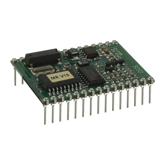
25 July 1996 Micro-reader Module Introduction 1.1 General This document provides information about the TIRIS Micro-reader Module RI-STU-MRD1. It describes the module and how to integrate it. 1.2 Product Description The Micro-reader is an intelligent module providing RF and Control functions to read and program TIRIS transponders. -
Page 6: Figure 1: Block Diagram Of The Micro-Reader
Micro-reader Module 25 July 1996 RESET- CRDM WLSC RDEN- MICRO SYNC CONTROLLER STAT RXCK GNDP RXDT- TXCT- ANT1 ASIC Power ANT2 stage ANTCAP Filter Figure 1: Block Diagram of the Micro-reader RECEIVE TXHI from RESONANCE ASIC CAPACITOR ANT1 TXLO from ANT2 ASIC ANTCAP... -
Page 7: Product Function
25 July 1996 Micro-reader Module Product Function 2.1 Description The Micro-reader module is an intelligent plug-in module which can be plugged into or soldered onto an application specific adapter board. It supports serial data communications between a PC and TIRIS transponders. With its Serial Communications Interface (SCI) the Micro-reader supports TTL data communications, which with the addition of a communications driver (for example: RS232 or RS422) allows communication to a standard interface. -
Page 8: Synchronization
Micro-reader Module 25 July 1996 2.1.3 Synchronization There are two possible methods of wired synchronization: 1. Connect a pulse waveform to all RDEN- input pins of the Micro-readers to be synchronized. The pulse would normally be at VSL, dropping to GND for 100 µs every 200 ms. 2. -
Page 9: Serial Communication
25 July 1996 Micro-reader Module In the default continuous read mode, only those valid RO, R/W or MPT IDs that differ from the previously read ID; or valid IDs read after a “NO READ”, are transferred via the SCI (Normal Mode) he Micro-reader can be set to transfer all valid IDs that are read (Line Mode) by means of a corresponding serial data command... -
Page 10: Table 1: Pin Connections
Micro-reader Module 25 July 1996 Table 1: Pin Connections Signal Name Function SYNC Output for wired synchronization RDEN- Input for wired synchronization and single read trigger Reserved, do not connect RESET- Reset of the Micro-reader Receive Data signal input of serial interface Transmit Data signal output of serial interface Reserved, do not connect Reserved, do not connect... - Page 11 25 July 1996 Micro-reader Module Pin Connection Description SYNC (1) Output for wired synchronization. This output is at GND level until the Micro-reader starts its read cycle, at which time it goes to VSL until the complete reading, programming or locking cycle is finished.
- Page 12 Micro-reader Module 25 July 1996 VSL (24) Pin 24 is for connecting the positive supply voltage (5 V) for the logic part. CRDM (26) Supplying pin 26 with a logic high signal causes the Micro-reader to run in a continuous charge-only read mode (see Section 2.1.5 for more information).
-
Page 13: Communications Protocol
25 July 1996 Micro-reader Module Communications Protocol 3.1 Protocol PC to Micro-reader Start Length Cmd 1 Cmd 2 Data Byte Contents (hexadecimal value) Start Mark (SOH, 01hex) Length Command Field (1) Command Field (2) (optional) 4(3) Data Field (1) N+3(2) Data Field (N) N+4(3) BCC Note: The total number of bytes sent within a protocol frame (including Start Mark and... -
Page 14: Command Field
Micro-reader Module 25 July 1996 3.1.3 Command Field The ‘Command Field(s)’ define the mode in which the Micro-reader operates and determines the operation that is to be carried out in the transponder. Depending on the setting of the relevant bits, the corresponding information specified in the Data Fields will be sent to the transponder or not. -
Page 15: Data Field
25 July 1996 Micro-reader Module Command Field (2) Command Field (2) is only present if bit 7 of Command Byte 1 is set. Setting Comment Special Write Timing If set, needs to be determined in Data Field (see 3.1.4) Wireless Synchronization 1/0 If set, wireless synchronization is used DBCC calculation If set, Micro-reader calculates DBCC... -
Page 16: Protocol Micro-Reader To Pc
Micro-reader Module 25 July 1996 3.2 Protocol Micro-reader to PC Start Length Status Data Byte Contents (hexadecimal value) Start Mark (SOH, 01hex) Length Status Data Field (1) (LSByte) Data Field (N) (MSByte) Refer to Section 6.2 for examples. 3.2.1 Start Mark The ‘Start-Mark’... -
Page 17: Data Field
25 July 1996 Micro-reader Module 3.2.4 Data Field Response # of Bytes Type in Data Field Comment Identification Data (LSByte first), see 5.2.1 Identification Data (LSByte first) ), see 5.2.2 MPT/SAMPT Identification Data (LSByte first), plus Read Address, see 5.2.3 Other Complete transponder protocol without pre-bits provided that a valid RO or R/W start byte was detected... -
Page 18: Specifications
Micro-reader Module 25 July 1996 4. Specifications 4.1 Absolute Maximum Ratings over operating free-air temperature range (unless otherwise noted) Supply voltage for power stage V_VSP 6.0 V Supply voltage for logic V_VSL 6.0 V Voltage on any pin (except ANT1) Vpin -0.6 V to V_VSL + 0.6 V Maximum output current sunk by an output pin... -
Page 19: Recommended Operating Conditions
25 July 1996 Micro-reader Module 4.2 Recommended Operating Conditions Symbol Parameter Min. Typ. Max. Unit V_VSP Supply voltage for power stage V_VSL Supply voltage for logic I_VSP Supply current for power stage 110* I_VSL Supply current for logic I_su Output current sunk by an output pin 15.0 I_so Output current sourced by an output pin... -
Page 20: Mechanical Data
Micro-reader Module 25 July 1996 4.4 Mechanical Data Parameter Minimum Typical Maximum Unit Length 37.9 38.3 38.7 Width 28.8 29.3 29.6 Height including pins 12.5 13.5 14.0 Weight Grams Recommended finished pin hole size is 1 mm diameter. Figure 4: Top, Front and Side View (measurements in mm) -
Page 21: Transponder Protocols
25 July 1996 Micro-reader Module 5. Transponder Protocols 5.1 Transponder commands This section describes the protocols that need to be sent by the PC to the transponder via the Micro- reader in order to execute the required function. 5.1.1 Read RO, R/W POWER BURST I READ RF TRANSMITTER... -
Page 22: Addressing Mpts/Sampts
Micro-reader Module 25 July 1996 5.1.3 Addressing MPTs/SAMPTs Since MPT/SAMPTs allow the execution of the different commands applicable to multiple pages the ‘Write Address’ needs to be sent within the protocol in order to determine the function to be executed with a specific MPT/SAMPT page. WRITE ADDRESS P P P P P P C C PAGE COMMAND... -
Page 23: Selective Read Page Of Sampt
25 July 1996 Micro-reader Module 5.1.3.4 Selective Read Page of SAMPT 32 - 56 bit 128 bit 8 - 32 WRITE READ OR SELECTIVE RF TRANSMITTER WRITE FRAME BCC POWER BURST I ADDRESS ADDRESS DISCHARGE 16 ms 16 - 64 ms 50 ms 32 ms 20 ms... -
Page 24: Read/Write Transponder
Micro-reader Module 25 July 1996 5.2.2 Read/Write Transponder START STOP DISCHARGE PRE BITS READ DATA END BITS IDENTIFICATION DATA DATA BCC IDENT. DATA 112 bits 16 bits Figure 14: R/W Read Data Format 5.2.3 MPT/SAMPT START READ DISCHARGE ADDR. PRE BITS READ DATA FBCC IDENTIFICATION DATA... -
Page 25: Communication Protocol Examples
25 July 1996 Micro-reader Module 6. Communication Protocol Examples 6.1 PC to Micro-reader Read RO, R/W Byte Content (hex) Comment Description Start Mark Length Two bytes follow excluding BCC Command Field (1) Perform Single command, send Power Burst I Data Field (1) Power Burst I with 50 ms duration (charge-up) BCC over previous bytes excluding Start Mark General Read Page of MPT... -
Page 26: Micro-Reader To Pc
Micro-reader Module 25 July 1996 6.2 Micro-reader to PC Successful Read of RO Byte Content (hex) Comment Description Start Mark Length 9 bytes follow excluding BCC Status Valid RO, Startbyte detected, DBCC O.K. Data Field (1) Identification Data (LSByte) Data Field (2) Identification Data - : - - : -... -
Page 27: Appendix A: Abbreviations
Non Return to Zero PB I Power Burst one PB II Power Burst two Radio Frequency RF-ID Radio Frequency Identification Read Only Transponder Read/Write Transponder Serial Communications Interface SAMPT Selective Addressable Multipage Transponder Software TIRIS Texas Instruments Registration and Identification System... -
Page 28: Appendix B: Signal Names
Micro-reader Module 25 July 1996 Appendix B: Signal Names RXCK Receiver Clock RXDT- Receiver Data Signal TXCT- RF - Transmitter Control Signal TXHI Positive Transmission Signal Output TXLO Negative Transmission Signal Output Appendix C: CE Declaration The Micro-reader module complies with the European CE requirements specified in the EMC Directive 89/336/EEC.